EP1607494A1 - Organic compound hydrogenation apparatus and method for hydrogenating organic compound - Google Patents
Organic compound hydrogenation apparatus and method for hydrogenating organic compound Download PDFInfo
- Publication number
- EP1607494A1 EP1607494A1 EP04717828A EP04717828A EP1607494A1 EP 1607494 A1 EP1607494 A1 EP 1607494A1 EP 04717828 A EP04717828 A EP 04717828A EP 04717828 A EP04717828 A EP 04717828A EP 1607494 A1 EP1607494 A1 EP 1607494A1
- Authority
- EP
- European Patent Office
- Prior art keywords
- cathode
- organic compound
- palladium
- reaction
- hydrogenation
- Prior art date
- Legal status (The legal status is an assumption and is not a legal conclusion. Google has not performed a legal analysis and makes no representation as to the accuracy of the status listed.)
- Granted
Links
Images


Classifications
-
- C—CHEMISTRY; METALLURGY
- C25—ELECTROLYTIC OR ELECTROPHORETIC PROCESSES; APPARATUS THEREFOR
- C25B—ELECTROLYTIC OR ELECTROPHORETIC PROCESSES FOR THE PRODUCTION OF COMPOUNDS OR NON-METALS; APPARATUS THEREFOR
- C25B3/00—Electrolytic production of organic compounds
- C25B3/20—Processes
- C25B3/25—Reduction
-
- C—CHEMISTRY; METALLURGY
- C25—ELECTROLYTIC OR ELECTROPHORETIC PROCESSES; APPARATUS THEREFOR
- C25B—ELECTROLYTIC OR ELECTROPHORETIC PROCESSES FOR THE PRODUCTION OF COMPOUNDS OR NON-METALS; APPARATUS THEREFOR
- C25B11/00—Electrodes; Manufacture thereof not otherwise provided for
- C25B11/04—Electrodes; Manufacture thereof not otherwise provided for characterised by the material
- C25B11/042—Electrodes formed of a single material
- C25B11/046—Alloys
-
- C—CHEMISTRY; METALLURGY
- C25—ELECTROLYTIC OR ELECTROPHORETIC PROCESSES; APPARATUS THEREFOR
- C25B—ELECTROLYTIC OR ELECTROPHORETIC PROCESSES FOR THE PRODUCTION OF COMPOUNDS OR NON-METALS; APPARATUS THEREFOR
- C25B11/00—Electrodes; Manufacture thereof not otherwise provided for
- C25B11/04—Electrodes; Manufacture thereof not otherwise provided for characterised by the material
- C25B11/051—Electrodes formed of electrocatalysts on a substrate or carrier
- C25B11/073—Electrodes formed of electrocatalysts on a substrate or carrier characterised by the electrocatalyst material
- C25B11/075—Electrodes formed of electrocatalysts on a substrate or carrier characterised by the electrocatalyst material consisting of a single catalytic element or catalytic compound
- C25B11/081—Electrodes formed of electrocatalysts on a substrate or carrier characterised by the electrocatalyst material consisting of a single catalytic element or catalytic compound the element being a noble metal
-
- C—CHEMISTRY; METALLURGY
- C25—ELECTROLYTIC OR ELECTROPHORETIC PROCESSES; APPARATUS THEREFOR
- C25B—ELECTROLYTIC OR ELECTROPHORETIC PROCESSES FOR THE PRODUCTION OF COMPOUNDS OR NON-METALS; APPARATUS THEREFOR
- C25B3/00—Electrolytic production of organic compounds
- C25B3/01—Products
- C25B3/03—Acyclic or carbocyclic hydrocarbons
-
- C—CHEMISTRY; METALLURGY
- C25—ELECTROLYTIC OR ELECTROPHORETIC PROCESSES; APPARATUS THEREFOR
- C25B—ELECTROLYTIC OR ELECTROPHORETIC PROCESSES FOR THE PRODUCTION OF COMPOUNDS OR NON-METALS; APPARATUS THEREFOR
- C25B3/00—Electrolytic production of organic compounds
- C25B3/01—Products
- C25B3/07—Oxygen containing compounds
-
- C—CHEMISTRY; METALLURGY
- C25—ELECTROLYTIC OR ELECTROPHORETIC PROCESSES; APPARATUS THEREFOR
- C25B—ELECTROLYTIC OR ELECTROPHORETIC PROCESSES FOR THE PRODUCTION OF COMPOUNDS OR NON-METALS; APPARATUS THEREFOR
- C25B3/00—Electrolytic production of organic compounds
- C25B3/01—Products
- C25B3/09—Nitrogen containing compounds
-
- C—CHEMISTRY; METALLURGY
- C25—ELECTROLYTIC OR ELECTROPHORETIC PROCESSES; APPARATUS THEREFOR
- C25B—ELECTROLYTIC OR ELECTROPHORETIC PROCESSES FOR THE PRODUCTION OF COMPOUNDS OR NON-METALS; APPARATUS THEREFOR
- C25B9/00—Cells or assemblies of cells; Constructional parts of cells; Assemblies of constructional parts, e.g. electrode-diaphragm assemblies; Process-related cell features
-
- C—CHEMISTRY; METALLURGY
- C25—ELECTROLYTIC OR ELECTROPHORETIC PROCESSES; APPARATUS THEREFOR
- C25B—ELECTROLYTIC OR ELECTROPHORETIC PROCESSES FOR THE PRODUCTION OF COMPOUNDS OR NON-METALS; APPARATUS THEREFOR
- C25B9/00—Cells or assemblies of cells; Constructional parts of cells; Assemblies of constructional parts, e.g. electrode-diaphragm assemblies; Process-related cell features
- C25B9/01—Electrolytic cells characterised by shape or form
- C25B9/015—Cylindrical cells
Definitions
- the present invention relates to an organic compound hydrogenation apparatus for conducting hydrogenation of an organic compound, and a method for hydrogenating the organic compound.
- hydrogenation (hydrogenating) reaction of an organic compound and the like has been utilized in various chemical fields and, for example, such hydrogenation reactions are actually utilized as cracking reaction of petroleum in which heavy oil is hydrogenated to obtain gasoline or kerosene and tar fraction is hydrogenised so that it is liquefied to be matched for more purposive use conditions. Further, hydrogenation is utilized in a reaction in which an unsaturated hydrocarbon is converted into a corresponding saturated hydrocarbon, and a reaction in which a halogenated compound is dehalogenated.
- the aforementioned palladium and many types of hydrogen storage metal alloy have catalysis, and since hydrogen in palladium or other hydrogen storage metals has strong reactivity as active hydrogen, it is said that the palladium and the like function as a hydrogen-supply source and hydrogenation catalyst to exert high function as a method for hydrogenating organic compounds.
- An object of the present invention is to provide a method for hydrogenating an organic compound and an organic compound hydrogenation apparatus which are capable of enhancing efficiency of hydrogenation of the organic compound.
- the cathode may be any tubular members, which have a polygonal cross section such as triangle, tetragon or pentagon, or may have a circular or ellipsoidal cross section. A plurality of tubular members may also be used.
- palladium, palladium alloy such as palladium-sliver alloy, rare-earth metal alloy such as lanthanum-nickel alloy, misch metal-nickel alloy, titanium, zirconium alloy and the like can be exemplified.
- a contact area between the organic compound and the inner surface of the cathode is sufficiently large, and thus desirably the surface of the contact portion is sufficiently roughened.
- blast treatment or etching treatment is desirable.
- a degree of treatment is not particularly limited, the blast treatment is preferably carried out by using an alumina grid having around 15 to 20 meshes, whereby substantial surface area becomes 2 to 3 times.
- reaction cell There is no particular limitation for a reaction cell as long as it has a size and shape that can incorporate the anode and cathode.
- the electrolytic solution with which the reaction cell is filled is not particularly limited as long as the solution generates hydrogen from the cathode at the time of the electrolysis.
- potassium hydroxide, sodium hydroxide and the like can be exemplified a basic electrolytic solution.
- aqueous sulfuric acid solution, aqueous hydrochloric acid solution and the like can be exemplified as an acidic electrolytic solution.
- the reaction formula is as shown below in Formula (II). H + + e - ⁇ Had
- Hab is an absorbed hydrogen.
- the Hab in Formula (III) reacts with the organic compound supplied inside the cathode to hydrogenate the organic compound.
- Hydrogen which has been absorbed in the cathode is consumed only when the cathode contacts with the organic compounds so that hydrogenation of the organic compound occurs.
- a consumed amount of hydrogen is produced along with the progress of the reaction, and is absorbed in the cathode, thereby leading to a state in which hydrogen is constantly absorbed in the cathode in an amount close to the maximum absorption amount.
- the hydrogenation reaction of the organic compound according to the present invention includes reduction reaction of aliphatic or aromatic unsaturated hydrocarbons having a double bond or a triple bond such as ethylene, propylene, 1-octene or 2-octene, acetylene, styrene and quinone into corresponding saturated hydrocarbons, the reaction generating ethane, propane, n-octene (Translator's comment: correctly, n-octane), ethane, ethylbenzene and hydroquinone, respectively.
- aliphatic or aromatic unsaturated hydrocarbons having a double bond or a triple bond such as ethylene, propylene, 1-octene or 2-octene, acetylene, styrene and quinone into corresponding saturated hydrocarbons
- the hydrogenation reaction of the organic compound according to the present invention also includes dehalogenation reaction of halogenated aromatic compounds such as 2-chlorophenol, 4-chlorotoluene and dioxins, the reaction generating phenol, toluene and dehalgenated compounds of dioxins, respectively.
- halogenated aromatic compounds such as 2-chlorophenol, 4-chlorotoluene and dioxins
- halogenated compound examples include halogenated aromatic compounds and halogenated aliphatic compounds, and examples of halogen include fluorine, chlorine, bromine and iodine.
- a bond of long chain hydrocarbon such as paraffin also can be broken by hydrogenation to generate two or more types of short chain hydrocarbon (cracking).
- the present invention can be applied to generate benzyl alcohol by hydrogenation of benzaldehyde and to generate nitrosobenzene or aniline by hydrogenation of nitrobenzene.
- the organic compound to be treated is not necessarily in liquid form, but may be in gaseous or solid form.
- gaseous form gas is passed through the cathode as pressurized gas as it stands or by being pressurized.
- gas may be blown into the cathode.
- solid it may be suspended in a solvent to be brought in contact with the cathode, or may be made into powder and blown as it stands into the cathode.
- the cathode is made of a material including a hydrogen storage material, and is arranged as a tubular member so that the organic compound as an object to be treated circulates inside, conducting electrolysis in a reaction cell filled with an electrolytic solution results in generation of hydrogen on the outer surface of the cathode, and the generated hydrogen is absorbed in the tube wall of the cathode.
- the organic compound circulating inside the tube is in a state surrounded by the tube wall of the cathode, it can easily contact with the tube wall in which hydrogen is absorbed, so that a contact area effective for hydrogenation of organic compounds becomes larger as compared to that of a conventional cathode having a division plate-like shape or the like, thereby enhancing the efficiency of hydrogenation of the organic compound.
- the cathode may also be formed on a support by coating or the like.
- the hydrogen storage material is palladium.
- the cathode is formed by providing surface treatment on an inner surface of the tubular member with the hydrogen storage material.
- example of the surface treatment of the hydrogen storage material on the inner surface of the cathode includes a surface treatment method in which palladium black is formed on the inner surface of the cathode by electrolytic reduction treatment of palladium chloride.
- the cathode is formed by filling the tubular member with the hydrogen storage material.
- the form of the hydrogen storage material in addition to hydrogen storage material having a shape of powder or fiber, a form in which the hydrogen storage material is supported or coated on various carriers having the shape can be used.
- the hydrogen storage material has a large surface area, which increases an area where the organic compound contacts effectively with hydrogen, reaction rate of the hydrogenation reaction can further be enhanced.
- those used for usual catalysts can be exemplified, including silica, alumina, silica-alumina, activated carbon, carbon fiber and the like.
- a method for hydrogenating an organic compound according to another aspect of the present invention to hydrogenate the organic compound includes the steps of: by using a reaction cell having an anode and a tubular cathode made of a hydrogen storage material, applying voltage between the anode and the cathode to electrolyze an electrolytic solution existing between the anode and the cathode; and circulating the organic compound as the object to be treated inside the tubular cathode to hydrogenate the organic compound.
- the present invention by electrolyzing the electrolytic solution existing between the anode and cathode, while circulating the organic compound as an object to be treated inside the tube of the cathode, hydrogen is generated on the outer surface of the cathode and the generated hydrogen is absorbed in the tube wall of the cathode. Further, since the circulating organic compound is in a state surrounded by the tube wall of the cathode, it can easily contact with the tube wall in which hydrogen has been absorbed, and the contact area effective for hydrogenation of the organic compound becomes larger as compared to the conventional division plate-like cathode and the like, thereby enhancing the efficiency of hydrogenation of the organic compound.
- feed rate of the organic compound is preferably controlled as needed in accordance with status of the reduction.
- Fig. 1 shows a hydrogenation apparatus 1 of an organic compound according to the embodiment of the present invention.
- the hydrogenation apparatus 1 is a hydrogenation apparatus for hydrogenating an organic compound, which includes a cylindrical reaction cell 13 having therein an anode 11 and a cathode 12 made of a material including a hydrogen storage material, a power source 14 for applying voltage to the anode 11 and cathode 12, an electrolytic solution pump 15 for supplying an electrolytic solution into the reaction cell 13, an electrolytic solution reservoir 16, an organic compound pump 17, and an organic compound reservoir 18.
- Examples of the organic compound as an object to be treated include liquid aliphatic or aromatic unsaturated hydrocarbons having a double bond or a triple bond such as ethylene, propylene, 1-octene and 2-octene, acetylene, styrene, quinones, paraffins, benzaldehyde and nitrobenzene.
- halogenated aromatic compounds such as 2-chlorophenol, 4-chlorotoluene and dioxins may be used as the organic compound as the object to be treated, the halogenated aromatic compounds being subjected to dehalogenation reaction.
- the cathode 12 is formed by a tubular member made of palladium, which divides the inside of the reaction cell 13 into an electrolytic chamber 13A and a hydrogenation chamber 12A (each described later) and penetrates the cylindrical reaction cell 13 along a central axis thereof and the organic compound as the object to be treated circulates inside the tubular member.
- An internal space of the tubular member is defined as the hydrogenation chamber 12A.
- Palladium black is formed on an inner surface of tubular member of the cathode 12 by electrolysis reduction treatment of palladium chloride.
- surface roughening treatment is provided to the inner surface of tubular member of the cathode 12.
- Blast treatment, etching treatment and the like can be exemplified as the surface roughening treatment.
- the reaction cell 13 is a cylindrical member with upper and lower sides thereof being closed with platy members, to which the electrolytic solution is supplied.
- a space excluding the cathode 12 in the reaction cell 13 defines the electrolytic chamber 13A.
- a discharge port 131 and a supply port 132 each corresponding to the inner diameter of the cathode 12 are formed at the centers of the platy members on the upper and lower sides of the reaction cell 13 for discharging and supplying the organic compound.
- a discharge port 133 and a supply port 134 for discharging and supplying an electrolytic solution are provided at a radially-outer part from the center of the platy member on the lower side of the reaction cell 13.
- a gas exhaust port 135 for exhausting gas generated from the electrolytic solution in the reaction cell 13 upon electrolysis is provided at a radially-outer part from the center of the platy member on the upper side of the reaction cell 13.
- discharge port 131, supply port 132, discharge port 133, supply port 134 and gas exhaust port 135 can be arbitrarily opened and closed by valves or the like.
- the reaction cell 13 is filled with the electrolytic solution.
- the electrolytic solution is aqueous sulfuric acid solution of 0.01 to 10 N (normal).
- the power source 14 is a voltage variable power source. A positive electrode of the power source 14 is connected to the anode 11, while a negative electrode of the power source 14 is connected to the cathode 12.
- the electrolytic solution pump 15 supplies the electrolytic solution stored in the electrolytic solution reservoir 16 into the reaction cell 13 via the supply port 134.
- a valve or the like may be provided between the electrolytic solution pump 15 and the supply port 134.
- the organic compound pump 17 supplies the organic compound stored in the organic compound reservoir 18 into the cathode 12 via the supply port 132.
- a valve or the like may be provided between the organic compound pump 17 and the supply port 132 to control feed rate of the organic compound.
- the electrolytic solution stored in the electrolytic solution reservoir 16 is supplied into the electrolytic chamber 13A of the reaction cell 13 via the supply port 134.
- the power source 14 is actuated to apply voltage between the anode 11 and cathode 12.
- the voltage applied between the anode 11 and cathode 12 is not particularly limited but, from the point of the apparatus, 0.1 to 100 V is preferable.
- the organic compound stored in the organic compound reservoir 18 is circulated inside the tube portion of cathode 12, that is, the hydrogenation chamber 12A via the supply port 132.
- feed rate of the organic compound can be controlled by adjusting the organic compound pump 17.
- Hydrogen absorbed in the cathode 12 (Hab in Formula (VI)) reaches the hydrogenation chamber 12A of the cathode 12, which reacts with the organic compound supplied to the hydrogenation chamber 12A to reduce the organic compound.
- reaction substrate 1 mmol of reaction substrate is dissolved in an organic solvent (such as methanol or ethyl acetate) to prepare 10 ml of a 0.1 M solution.
- organic solvent such as methanol or ethyl acetate
- Pre-electrolysis is previously conducted (around 100 to 500 mA, 500 C) up to a state in which palladium black on the inner surface of the palladium tube of the cathode 12 absorbs hydrogen sufficiently.
- electrolysis is conducted while circulating the prepared solution inside the tube at various flow rates.
- Electrolysis current value is suitably set while considering both of time period for reaction and current efficiency.
- electrolysis is preferably conducted with a large current value. However, in this case, current efficiency is lowered.
- a small current value is selected. However, in this case, the reaction time increases.
- the present invention is not limited to the aforementioned embodiment, and any variations and improvements are included in the present invention so far as the object of the present invention can be achieved.
- platinum is used as the anode 11 in the aforementioned embodiment, carbon, nickel, stainless-steel or the like may also be used.
- the cathode 12 may have a polygonal cross section such as triangle, quadrangle and pentagon, or may have elliptic cross section.
- the cathode 12 is made of palladium in the aforementioned embodiment, the cathode 12 may be made of palladium alloy such as palladium-silver alloy, rare-earth metal alloy such as lanthanum-nickel alloy, misch meta-nickel alloy, a titanium alloy or a zirconium alloy.
- palladium alloy such as palladium-silver alloy, rare-earth metal alloy such as lanthanum-nickel alloy, misch meta-nickel alloy, a titanium alloy or a zirconium alloy.
- the cathode 12 may be filled with hydrogen storage material inside the tubular member.
- the form of the hydrogen storage material in addition to hydrogen storage material having a shape of powder, fiber or the like, a form in which the hydrogen storage material is supported or coated on various carriers having the above-described shape can be used.
- the aforementioned hydrogen storage material has a large surface area, which increases area where the organic compound and hydrogen contact effectively, thereby further enhancing reaction rate.
- those used for usual catalysts can be exemplified, including silica, alumina, silica-alumina, activated carbon, carbon fiber and the like.
- the organic compound to be treated is in liquid form in the aforementioned embodiment, the organic compound may be in gaseous or solid form.
- gaseous form gas is passed through the cathode 12 as pressurized gas as it stands or after being pressurized. In order to allow the reaction to proceed better, gas may be blown into the cathode 12.
- solid it may be suspended in a solvent and brought into contact with the cathode, or may be made into powder and blown as it stands into the cathode.
- Ethyl cinnamate was used as an unsaturated organic compound and hydrogenation was conducted under the same measurement conditions as those in Examples 1 to 5. Then, yield and current efficiency were obtained in the same way as described above. Measurement conditions and measurement results are shown in Fig. 4.
- the hydrogenation apparatus 1 according to the present invention had very high yield and current efficiency as compared to the conventional hydrogenation apparatus provided with the palladium plate even under the same reaction conditions, and that the hydrogenation apparatus was highly-effective as compared to the conventional one.
- Example 6 Furthermore, an inner surface area of the palladium tube in Example 6 was 7 cm 2 and the surface area of the palladium plate in Comparison was 2.2 cm 2 . Calculation of current efficiency per unit area based on these surface areas gave 13%/cm 2 for Example 6 and, on the other hand, 4.5%/cm 2 for Comparison. From the result, it was confirmed that the hydrogenation apparatus 1 in Example 6 has a higher current efficiency per unit area.
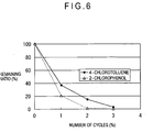
- 2-chlorophenol was dechlorinated and, at the same time, yield, current efficiency and current efficiency per unit area were compared between conditions where a palladium tube electrode was used and a palladium plate electrode was used.
- the present invention can be used advantageously, for example, as a hydrogenation apparatus for use in hydrogenating unsaturated hydrocarbons, halogenated compounds, long chain hydrocarbons and the like, and as a method for hydrogenating the same.
Landscapes
- Chemical & Material Sciences (AREA)
- Organic Chemistry (AREA)
- Engineering & Computer Science (AREA)
- Chemical Kinetics & Catalysis (AREA)
- Electrochemistry (AREA)
- Materials Engineering (AREA)
- Metallurgy (AREA)
- Electrolytic Production Of Non-Metals, Compounds, Apparatuses Therefor (AREA)
- Organic Low-Molecular-Weight Compounds And Preparation Thereof (AREA)
Abstract
Description
Claims (5)
- An organic compound hydrogenation apparatus for hydrogenating an organic compound comprising:wherein the cathode is made of a material including a hydrogen storage material, the cathode being arranged as a tubular member so that the organic compound as an object to be treated circulates thereinside.a reaction cell to which an electrolytic solution is supplied; andan anode and a cathode arranged in the reaction cell,
- The organic compound hydrogenation apparatus according to claim 1, wherein the hydrogen storage material is palladium.
- The organic compound hydrogenation apparatus according to claim 1 or 2, wherein the cathode is formed by providing surface treatment on an inner surface of the tubular member with the hydrogen storage material.
- The organic compound hydrogenation apparatus according to claim 1 or 2, wherein the cathode is formed by filling the tubular member with the hydrogen storage material.
- A method for hydrogenating an organic compound to hydrogenate the organic compound comprising:by using a reaction cell having an anode and a tubular cathode made of a hydrogen storage material, applying voltage between the anode and the cathode to electrolyze an electrolytic solution existing between the anode and the cathode; andcirculating the organic compound as the object to be treated inside the tubular cathode to hydrogenate the organic compound .
Applications Claiming Priority (3)
| Application Number | Priority Date | Filing Date | Title |
|---|---|---|---|
| JP2003059058 | 2003-03-05 | ||
| JP2003059058 | 2003-03-05 | ||
| PCT/JP2004/002826 WO2004079050A1 (en) | 2003-03-05 | 2004-03-05 | Organic compound hydrogenation apparatus and method for hydrogenating organic compound |
Publications (3)
| Publication Number | Publication Date |
|---|---|
| EP1607494A1 true EP1607494A1 (en) | 2005-12-21 |
| EP1607494A4 EP1607494A4 (en) | 2007-01-03 |
| EP1607494B1 EP1607494B1 (en) | 2014-02-12 |
Family
ID=32958818
Family Applications (1)
| Application Number | Title | Priority Date | Filing Date |
|---|---|---|---|
| EP04717828.0A Expired - Lifetime EP1607494B1 (en) | 2003-03-05 | 2004-03-05 | Organic compound hydrogenation apparatus and method for hydrogenating organic compound |
Country Status (6)
| Country | Link |
|---|---|
| US (1) | US7846319B2 (en) |
| EP (1) | EP1607494B1 (en) |
| JP (1) | JPWO2004079050A1 (en) |
| KR (1) | KR101073274B1 (en) |
| CN (1) | CN1756860B (en) |
| WO (1) | WO2004079050A1 (en) |
Families Citing this family (12)
| Publication number | Priority date | Publication date | Assignee | Title |
|---|---|---|---|---|
| US9005422B2 (en) * | 2007-08-31 | 2015-04-14 | Energy & Environmental Research Center Foundation | Electrochemical process for the preparation of nitrogen fertilizers |
| US8152988B2 (en) | 2007-08-31 | 2012-04-10 | Energy & Enviromental Research Center Foundation | Electrochemical process for the preparation of nitrogen fertilizers |
| US20090159454A1 (en) * | 2007-12-20 | 2009-06-25 | Air Products And Chemicals, Inc. | Divided electrochemical cell and low cost high purity hydride gas production process |
| JP5260128B2 (en) * | 2008-04-23 | 2013-08-14 | 出光興産株式会社 | Organic compound reduction method and reduction treatment apparatus |
| JPWO2010104028A1 (en) * | 2009-03-10 | 2012-09-13 | 学校法人慶應義塾 | Process for producing aromatic halogen compounds using electrolysis |
| WO2010124041A1 (en) * | 2009-04-22 | 2010-10-28 | Grt, Inc. | Process for converting hydrocarbon feedstocks with electrolytic and photoelectrocatalytic recovery of halogens |
| JP2013084360A (en) * | 2011-10-06 | 2013-05-09 | Hitachi Ltd | Membrane-electrode assembly, and device for organic hydride production |
| EP2980276B1 (en) * | 2013-03-29 | 2019-05-08 | JX Nippon Oil & Energy Corporation | Electrochemical reduction device and production method for hydrogenated product of aromatic compound |
| CN103938220B (en) * | 2014-04-29 | 2016-08-24 | 北京化工大学 | Electrolysis prepares method and the electrolysis unit of hydrodiazo benzene-like compounds |
| US10633749B2 (en) * | 2014-07-23 | 2020-04-28 | Board Of Trustees Of Michigan State University | Electrolyzer reactor and related methods |
| CN104141147B (en) * | 2014-08-01 | 2016-08-24 | 太原理工大学 | Microbiological fuel cell self-driven microorganism electrolysis cell hydrogen-preparing hydrogen-storing method |
| CN114959752B (en) * | 2022-04-29 | 2024-02-13 | 浙江工业大学 | Electrochemical reactor, system and application in electrolytic synthesis of 2,6-dichlorobenzonitrile |
Family Cites Families (9)
| Publication number | Priority date | Publication date | Assignee | Title |
|---|---|---|---|---|
| DE2323091A1 (en) * | 1973-05-04 | 1974-11-21 | Schering Ag | ELECTROCATALYTIC HYDRATION PROCESS |
| US4547273A (en) * | 1984-06-07 | 1985-10-15 | Energy Conversion Devices, Inc. | Mobile atom insertion reaction, mobile atom transmissive membrane for carrying out the reaction, and reactor incorporating the mobile atom transmissive membrane |
| JPS6270203A (en) * | 1985-09-20 | 1987-03-31 | Nippon Paionikusu Kk | Removal of hydrogen gas |
| US5358553A (en) * | 1991-07-05 | 1994-10-25 | Texaco Inc. | Membrane and separation process |
| KR960001176A (en) * | 1994-06-09 | 1996-01-25 | 유재목 | Electrolysis device for welding machine |
| JPH09184086A (en) | 1995-12-28 | 1997-07-15 | Permelec Electrode Ltd | Method for hydrogenating organic compound and electrolytic cell |
| JP3561108B2 (en) * | 1997-01-07 | 2004-09-02 | ペルメレック電極株式会社 | Hydrogenation method and electrolytic cell |
| JP4223619B2 (en) * | 1999-02-15 | 2009-02-12 | ペルメレック電極株式会社 | Electrolytic cathode and electrolytic cell equipped with the cathode |
| JP2001316315A (en) * | 2000-05-02 | 2001-11-13 | Permelec Electrode Ltd | Method for selectively hydrogenating alkenes |
-
2004
- 2004-03-05 EP EP04717828.0A patent/EP1607494B1/en not_active Expired - Lifetime
- 2004-03-05 KR KR1020057016394A patent/KR101073274B1/en not_active Expired - Fee Related
- 2004-03-05 WO PCT/JP2004/002826 patent/WO2004079050A1/en not_active Ceased
- 2004-03-05 US US10/547,675 patent/US7846319B2/en not_active Expired - Fee Related
- 2004-03-05 CN CN2004800059368A patent/CN1756860B/en not_active Expired - Fee Related
- 2004-03-05 JP JP2005503125A patent/JPWO2004079050A1/en active Pending
Also Published As
| Publication number | Publication date |
|---|---|
| KR101073274B1 (en) | 2011-10-12 |
| EP1607494B1 (en) | 2014-02-12 |
| KR20060007370A (en) | 2006-01-24 |
| WO2004079050A1 (en) | 2004-09-16 |
| EP1607494A4 (en) | 2007-01-03 |
| US7846319B2 (en) | 2010-12-07 |
| CN1756860B (en) | 2010-05-26 |
| US20070000788A1 (en) | 2007-01-04 |
| CN1756860A (en) | 2006-04-05 |
| JPWO2004079050A1 (en) | 2006-06-08 |
Similar Documents
| Publication | Publication Date | Title |
|---|---|---|
| US7846319B2 (en) | Organic compound hydrogenation apparatus and method for hydrogenating organic compound | |
| Gao et al. | Sequential catalysis enables enhanced C–C coupling towards multi-carbon alkenes and alcohols in carbon dioxide reduction: a study on bifunctional Cu/Au electrocatalysts | |
| JP5017499B2 (en) | How to reduce carbon dioxide | |
| US8617375B2 (en) | Method for reducing carbon dioxide | |
| Cyr et al. | The efficient electrochemical reduction of nitrobenzene and azoxybenzene to aniline in neutral and basic aqueous methanolic solutions at devarda copper and raney nickel electrodes: electrocatalytic hydrogenolysis of N O and N N bonds | |
| JP4223619B2 (en) | Electrolytic cathode and electrolytic cell equipped with the cathode | |
| Santana et al. | Electrocatalytic hydrogenation of organic compounds using a nickel sacrificial anode | |
| Lou et al. | Efficient dechlorination of α-halocarbonyl and α-haloallyl pollutants by electroreduction on bismuth | |
| EP3029177B1 (en) | Electrochemical reduction apparatus, and production method for hydrogenated aromatic compound | |
| JP2022540185A (en) | Process for the electrolytic dicarboxylation of at least one alkene with carbon dioxide CO2 in the presence of hydrogen H2 | |
| JP5017498B2 (en) | How to reduce carbon dioxide | |
| JP3561108B2 (en) | Hydrogenation method and electrolytic cell | |
| JPH09184086A (en) | Method for hydrogenating organic compound and electrolytic cell | |
| JP4907748B2 (en) | How to reduce carbon dioxide | |
| Santana et al. | Electrocatalytic hydrogenation of organic compounds using current density gradient and sacrificial anode of nickel | |
| Sakellaropoulos et al. | Electrocatalysis; selective electrogenerative reduction of organic halides | |
| EP2980276B1 (en) | Electrochemical reduction device and production method for hydrogenated product of aromatic compound | |
| JP4128638B2 (en) | Electrolysis method and electrolysis apparatus | |
| EP4700157A1 (en) | Organic hydride production device and organic hydride production method | |
| WO2012011208A1 (en) | Method for reducing carbon dioxide | |
| EP4257540A1 (en) | Organic hydride preparation system, control device of organic hydride preparation system, and control method of organic hydride preparation system | |
| CN121087506A (en) | Method for preparing trans-1, 2-dichloroethylene by electrocatalytic reaction | |
| WO2011135781A1 (en) | Method for reducing carbon dioxide |
Legal Events
| Date | Code | Title | Description |
|---|---|---|---|
| PUAI | Public reference made under article 153(3) epc to a published international application that has entered the european phase |
Free format text: ORIGINAL CODE: 0009012 |
|
| 17P | Request for examination filed |
Effective date: 20050923 |
|
| AK | Designated contracting states |
Kind code of ref document: A1 Designated state(s): AT BE BG CH CY CZ DE DK EE ES FI FR GB GR HU IE IT LI LU MC NL PL PT RO SE SI SK TR |
|
| AX | Request for extension of the european patent |
Extension state: AL LT LV MK |
|
| DAX | Request for extension of the european patent (deleted) | ||
| A4 | Supplementary search report drawn up and despatched |
Effective date: 20061201 |
|
| RIC1 | Information provided on ipc code assigned before grant |
Ipc: C25B 3/04 20060101AFI20061127BHEP Ipc: C25B 9/00 20060101ALI20061127BHEP |
|
| 17Q | First examination report despatched |
Effective date: 20130204 |
|
| GRAP | Despatch of communication of intention to grant a patent |
Free format text: ORIGINAL CODE: EPIDOSNIGR1 |
|
| INTG | Intention to grant announced |
Effective date: 20130912 |
|
| GRAS | Grant fee paid |
Free format text: ORIGINAL CODE: EPIDOSNIGR3 |
|
| GRAA | (expected) grant |
Free format text: ORIGINAL CODE: 0009210 |
|
| AK | Designated contracting states |
Kind code of ref document: B1 Designated state(s): AT BE BG CH CY CZ DE DK EE ES FI FR GB GR HU IE IT LI LU MC NL PL PT RO SE SI SK TR |
|
| REG | Reference to a national code |
Ref country code: GB Ref legal event code: FG4D |
|
| REG | Reference to a national code |
Ref country code: CH Ref legal event code: EP |
|
| REG | Reference to a national code |
Ref country code: AT Ref legal event code: REF Ref document number: 652212 Country of ref document: AT Kind code of ref document: T Effective date: 20140215 |
|
| REG | Reference to a national code |
Ref country code: DE Ref legal event code: R096 Ref document number: 602004044375 Country of ref document: DE Effective date: 20140320 |
|
| REG | Reference to a national code |
Ref country code: IE Ref legal event code: FG4D |
|
| REG | Reference to a national code |
Ref country code: NL Ref legal event code: VDEP Effective date: 20140212 |
|
| PGFP | Annual fee paid to national office [announced via postgrant information from national office to epo] |
Ref country code: GB Payment date: 20140305 Year of fee payment: 11 |
|
| REG | Reference to a national code |
Ref country code: AT Ref legal event code: MK05 Ref document number: 652212 Country of ref document: AT Kind code of ref document: T Effective date: 20140212 |
|
| PG25 | Lapsed in a contracting state [announced via postgrant information from national office to epo] |
Ref country code: NL Free format text: LAPSE BECAUSE OF FAILURE TO SUBMIT A TRANSLATION OF THE DESCRIPTION OR TO PAY THE FEE WITHIN THE PRESCRIBED TIME-LIMIT Effective date: 20140212 Ref country code: FI Free format text: LAPSE BECAUSE OF FAILURE TO SUBMIT A TRANSLATION OF THE DESCRIPTION OR TO PAY THE FEE WITHIN THE PRESCRIBED TIME-LIMIT Effective date: 20140212 Ref country code: PT Free format text: LAPSE BECAUSE OF FAILURE TO SUBMIT A TRANSLATION OF THE DESCRIPTION OR TO PAY THE FEE WITHIN THE PRESCRIBED TIME-LIMIT Effective date: 20140612 Ref country code: CY Free format text: LAPSE BECAUSE OF FAILURE TO SUBMIT A TRANSLATION OF THE DESCRIPTION OR TO PAY THE FEE WITHIN THE PRESCRIBED TIME-LIMIT Effective date: 20140212 Ref country code: ES Free format text: LAPSE BECAUSE OF FAILURE TO SUBMIT A TRANSLATION OF THE DESCRIPTION OR TO PAY THE FEE WITHIN THE PRESCRIBED TIME-LIMIT Effective date: 20140212 Ref country code: SE Free format text: LAPSE BECAUSE OF FAILURE TO SUBMIT A TRANSLATION OF THE DESCRIPTION OR TO PAY THE FEE WITHIN THE PRESCRIBED TIME-LIMIT Effective date: 20140212 Ref country code: AT Free format text: LAPSE BECAUSE OF FAILURE TO SUBMIT A TRANSLATION OF THE DESCRIPTION OR TO PAY THE FEE WITHIN THE PRESCRIBED TIME-LIMIT Effective date: 20140212 |
|
| PG25 | Lapsed in a contracting state [announced via postgrant information from national office to epo] |
Ref country code: BE Free format text: LAPSE BECAUSE OF FAILURE TO SUBMIT A TRANSLATION OF THE DESCRIPTION OR TO PAY THE FEE WITHIN THE PRESCRIBED TIME-LIMIT Effective date: 20140212 |
|
| PG25 | Lapsed in a contracting state [announced via postgrant information from national office to epo] |
Ref country code: DK Free format text: LAPSE BECAUSE OF FAILURE TO SUBMIT A TRANSLATION OF THE DESCRIPTION OR TO PAY THE FEE WITHIN THE PRESCRIBED TIME-LIMIT Effective date: 20140212 Ref country code: RO Free format text: LAPSE BECAUSE OF FAILURE TO SUBMIT A TRANSLATION OF THE DESCRIPTION OR TO PAY THE FEE WITHIN THE PRESCRIBED TIME-LIMIT Effective date: 20140212 Ref country code: CZ Free format text: LAPSE BECAUSE OF FAILURE TO SUBMIT A TRANSLATION OF THE DESCRIPTION OR TO PAY THE FEE WITHIN THE PRESCRIBED TIME-LIMIT Effective date: 20140212 Ref country code: EE Free format text: LAPSE BECAUSE OF FAILURE TO SUBMIT A TRANSLATION OF THE DESCRIPTION OR TO PAY THE FEE WITHIN THE PRESCRIBED TIME-LIMIT Effective date: 20140212 |
|
| REG | Reference to a national code |
Ref country code: CH Ref legal event code: PL |
|
| REG | Reference to a national code |
Ref country code: DE Ref legal event code: R097 Ref document number: 602004044375 Country of ref document: DE |
|
| PG25 | Lapsed in a contracting state [announced via postgrant information from national office to epo] |
Ref country code: MC Free format text: LAPSE BECAUSE OF FAILURE TO SUBMIT A TRANSLATION OF THE DESCRIPTION OR TO PAY THE FEE WITHIN THE PRESCRIBED TIME-LIMIT Effective date: 20140212 Ref country code: SK Free format text: LAPSE BECAUSE OF FAILURE TO SUBMIT A TRANSLATION OF THE DESCRIPTION OR TO PAY THE FEE WITHIN THE PRESCRIBED TIME-LIMIT Effective date: 20140212 Ref country code: PL Free format text: LAPSE BECAUSE OF FAILURE TO SUBMIT A TRANSLATION OF THE DESCRIPTION OR TO PAY THE FEE WITHIN THE PRESCRIBED TIME-LIMIT Effective date: 20140212 |
|
| PLBE | No opposition filed within time limit |
Free format text: ORIGINAL CODE: 0009261 |
|
| STAA | Information on the status of an ep patent application or granted ep patent |
Free format text: STATUS: NO OPPOSITION FILED WITHIN TIME LIMIT |
|
| REG | Reference to a national code |
Ref country code: IE Ref legal event code: MM4A |
|
| 26N | No opposition filed |
Effective date: 20141113 |
|
| PG25 | Lapsed in a contracting state [announced via postgrant information from national office to epo] |
Ref country code: LI Free format text: LAPSE BECAUSE OF NON-PAYMENT OF DUE FEES Effective date: 20140331 Ref country code: IE Free format text: LAPSE BECAUSE OF NON-PAYMENT OF DUE FEES Effective date: 20140305 Ref country code: CH Free format text: LAPSE BECAUSE OF NON-PAYMENT OF DUE FEES Effective date: 20140331 |
|
| REG | Reference to a national code |
Ref country code: DE Ref legal event code: R097 Ref document number: 602004044375 Country of ref document: DE Effective date: 20141113 |
|
| PG25 | Lapsed in a contracting state [announced via postgrant information from national office to epo] |
Ref country code: IT Free format text: LAPSE BECAUSE OF FAILURE TO SUBMIT A TRANSLATION OF THE DESCRIPTION OR TO PAY THE FEE WITHIN THE PRESCRIBED TIME-LIMIT Effective date: 20140212 |
|
| PG25 | Lapsed in a contracting state [announced via postgrant information from national office to epo] |
Ref country code: SI Free format text: LAPSE BECAUSE OF FAILURE TO SUBMIT A TRANSLATION OF THE DESCRIPTION OR TO PAY THE FEE WITHIN THE PRESCRIBED TIME-LIMIT Effective date: 20140212 |
|
| GBPC | Gb: european patent ceased through non-payment of renewal fee |
Effective date: 20150305 |
|
| PG25 | Lapsed in a contracting state [announced via postgrant information from national office to epo] |
Ref country code: GB Free format text: LAPSE BECAUSE OF NON-PAYMENT OF DUE FEES Effective date: 20150305 |
|
| REG | Reference to a national code |
Ref country code: FR Ref legal event code: PLFP Year of fee payment: 13 |
|
| PG25 | Lapsed in a contracting state [announced via postgrant information from national office to epo] |
Ref country code: BG Free format text: LAPSE BECAUSE OF FAILURE TO SUBMIT A TRANSLATION OF THE DESCRIPTION OR TO PAY THE FEE WITHIN THE PRESCRIBED TIME-LIMIT Effective date: 20140212 |
|
| PG25 | Lapsed in a contracting state [announced via postgrant information from national office to epo] |
Ref country code: GR Free format text: LAPSE BECAUSE OF FAILURE TO SUBMIT A TRANSLATION OF THE DESCRIPTION OR TO PAY THE FEE WITHIN THE PRESCRIBED TIME-LIMIT Effective date: 20140513 |
|
| PG25 | Lapsed in a contracting state [announced via postgrant information from national office to epo] |
Ref country code: HU Free format text: LAPSE BECAUSE OF FAILURE TO SUBMIT A TRANSLATION OF THE DESCRIPTION OR TO PAY THE FEE WITHIN THE PRESCRIBED TIME-LIMIT; INVALID AB INITIO Effective date: 20040305 Ref country code: LU Free format text: LAPSE BECAUSE OF NON-PAYMENT OF DUE FEES Effective date: 20140305 Ref country code: TR Free format text: LAPSE BECAUSE OF FAILURE TO SUBMIT A TRANSLATION OF THE DESCRIPTION OR TO PAY THE FEE WITHIN THE PRESCRIBED TIME-LIMIT Effective date: 20140212 |
|
| REG | Reference to a national code |
Ref country code: FR Ref legal event code: PLFP Year of fee payment: 14 |
|
| PGFP | Annual fee paid to national office [announced via postgrant information from national office to epo] |
Ref country code: DE Payment date: 20170228 Year of fee payment: 14 Ref country code: FR Payment date: 20170213 Year of fee payment: 14 |
|
| REG | Reference to a national code |
Ref country code: DE Ref legal event code: R119 Ref document number: 602004044375 Country of ref document: DE |
|
| PG25 | Lapsed in a contracting state [announced via postgrant information from national office to epo] |
Ref country code: DE Free format text: LAPSE BECAUSE OF NON-PAYMENT OF DUE FEES Effective date: 20181002 |
|
| PG25 | Lapsed in a contracting state [announced via postgrant information from national office to epo] |
Ref country code: FR Free format text: LAPSE BECAUSE OF NON-PAYMENT OF DUE FEES Effective date: 20180331 |