EP1607257A2 - Drive apparatus for opening/closing body for vehicle - Google Patents
Drive apparatus for opening/closing body for vehicle Download PDFInfo
- Publication number
- EP1607257A2 EP1607257A2 EP05012889A EP05012889A EP1607257A2 EP 1607257 A2 EP1607257 A2 EP 1607257A2 EP 05012889 A EP05012889 A EP 05012889A EP 05012889 A EP05012889 A EP 05012889A EP 1607257 A2 EP1607257 A2 EP 1607257A2
- Authority
- EP
- European Patent Office
- Prior art keywords
- opening
- pulse signal
- closing
- closing body
- drive apparatus
- Prior art date
- Legal status (The legal status is an assumption and is not a legal conclusion. Google has not performed a legal analysis and makes no representation as to the accuracy of the status listed.)
- Withdrawn
Links
- 238000000034 method Methods 0.000 description 12
- 230000005540 biological transmission Effects 0.000 description 7
- 238000004519 manufacturing process Methods 0.000 description 2
- 238000002360 preparation method Methods 0.000 description 2
- BGPVFRJUHWVFKM-UHFFFAOYSA-N N1=C2C=CC=CC2=[N+]([O-])C1(CC1)CCC21N=C1C=CC=CC1=[N+]2[O-] Chemical compound N1=C2C=CC=CC2=[N+]([O-])C1(CC1)CCC21N=C1C=CC=CC1=[N+]2[O-] BGPVFRJUHWVFKM-UHFFFAOYSA-N 0.000 description 1
- 238000005452 bending Methods 0.000 description 1
- 230000002093 peripheral effect Effects 0.000 description 1
Images


Classifications
-
- B—PERFORMING OPERATIONS; TRANSPORTING
- B60—VEHICLES IN GENERAL
- B60J—WINDOWS, WINDSCREENS, NON-FIXED ROOFS, DOORS, OR SIMILAR DEVICES FOR VEHICLES; REMOVABLE EXTERNAL PROTECTIVE COVERINGS SPECIALLY ADAPTED FOR VEHICLES
- B60J7/00—Non-fixed roofs; Roofs with movable panels, e.g. rotary sunroofs
- B60J7/02—Non-fixed roofs; Roofs with movable panels, e.g. rotary sunroofs of sliding type, e.g. comprising guide shoes
- B60J7/04—Non-fixed roofs; Roofs with movable panels, e.g. rotary sunroofs of sliding type, e.g. comprising guide shoes with rigid plate-like element or elements, e.g. open roofs with harmonica-type folding rigid panels
- B60J7/05—Non-fixed roofs; Roofs with movable panels, e.g. rotary sunroofs of sliding type, e.g. comprising guide shoes with rigid plate-like element or elements, e.g. open roofs with harmonica-type folding rigid panels pivoting upwardly to vent mode and moving downward before sliding to fully open mode
-
- B—PERFORMING OPERATIONS; TRANSPORTING
- B60—VEHICLES IN GENERAL
- B60J—WINDOWS, WINDSCREENS, NON-FIXED ROOFS, DOORS, OR SIMILAR DEVICES FOR VEHICLES; REMOVABLE EXTERNAL PROTECTIVE COVERINGS SPECIALLY ADAPTED FOR VEHICLES
- B60J7/00—Non-fixed roofs; Roofs with movable panels, e.g. rotary sunroofs
- B60J7/02—Non-fixed roofs; Roofs with movable panels, e.g. rotary sunroofs of sliding type, e.g. comprising guide shoes
- B60J7/04—Non-fixed roofs; Roofs with movable panels, e.g. rotary sunroofs of sliding type, e.g. comprising guide shoes with rigid plate-like element or elements, e.g. open roofs with harmonica-type folding rigid panels
- B60J7/057—Driving or actuating arrangements e.g. manually operated levers or knobs
Definitions
- This invention generally relates to a drive apparatus for an opening/closing body for a vehicle. More specifically, this invention pertains to a drive apparatus for an opening/closing apparatus for a vehicle for moving an opening/closing body of a vehicle.
- a drive apparatus for an opening/closing body such as a sunroof panel and a sunshade panel provided at a roof of a vehicle, a roof panel and a back window panel of a convertible, a swing door and a tail gate provided at sides or rear portion of the vehicle, a window panel provided at a door of a vehicle
- a conventional drive apparatus including a rotational drive apparatus, a drive unit including a reduction gear mechanism linked with a rotational shaft of the rotational drive apparatus and an output member linked with the rotational shaft through a reduction gear mechanism and linked with an opening/closing body through a connection member, a pulse signal generator provided at the drive unit and generating a pulse signal on the basis of rotations of the rotational shaft, and a control means for calculating a position of the opening/closing body in relation to opening and closing on the basis of the pulse signal emitted by the pulse signal generator and for controlling stop of the rotational drive apparatus on the basis of the position of the opening/clo
- the drive unit includes a position-detecting means for detecting that the connection member achieves a predetermined base position provided between the drive unit and the connection member.
- a position-detecting means for detecting that the connection member achieves a predetermined base position provided between the drive unit and the connection member.
- the position-detecting means detects the base position through the connection member. Accordingly, a detected portion of the connection member detected by the position-detecting member becomes the base position only once in a whole stroke for opening and closing the opening/closing body. In other words, chance for detecting the base position by the position-detecting means is obtained only once in the whole stroke for opening and closing the opening/closing body. Therefore, depending on a width of a range of opening and closing the opening/closing body, when the opening/closing body is opened or closed in only a range that the connection member does not achieve the base position, the calculation of position of the opening/closing body on the basis of pulse signals generated by the pulse signal generator cannot be corrected. As a result, there is a danger that the control means does not recognize the predetermined position accurately.
- a drive apparatus for an opening/closing body (13) for a vehicle includes a drive unit (4) including a rotational drive apparatus (41), a reduction gear mechanism (42) linked with a rotational shaft (41a) of the rotational drive apparatus, and an output member (46c) linked with the rotational shaft through the reduction gear mechanism and linked with the opening/closing body through a connection member (23, 3), a first pulse signal generator (6) provided at the drive unit and generating a first pulse signal on the basis of a rotation of the rotational shaft, and a control means (5) for calculating an opening/closing position of the opening/closing body on the basis of the first pulse signal emitted by the first pulse signal generator and controlling the rotational drive apparatus corresponding to the opening/closing position of the opening/closing body.
- a drive unit (4) including a rotational drive apparatus (41), a reduction gear mechanism (42) linked with a rotational shaft (41a) of the rotational drive apparatus, and an output member (46c) linked with
- the drive apparatus for an opening/closing body for a vehicle is characterized in that the opening/closing apparatus further comprises a second pulse signal generator (8) provided at the drive unit and generating a second pulse signal on the basis of a rotation of either one of the reduction gear mechanism and the output member, and the control means calculates an opening/closing position of the opening/closing body on the basis of the first pulse signal emitted by the first pulse signal generator utilizing the second pulse signal emitted by the second pulse signal generator as a base point and controls the rotational drive apparatus corresponding to the opening/closing position of the opening/closing body.
- a second pulse signal generator provided at the drive unit and generating a second pulse signal on the basis of a rotation of either one of the reduction gear mechanism and the output member
- the control means calculates an opening/closing position of the opening/closing body on the basis of the first pulse signal emitted by the first pulse signal generator utilizing the second pulse signal emitted by the second pulse signal generator as a base point and
- a pulse signal emitted by the second pulse signal generator corresponds to a rotation of the reduction gear mechanism or the output member for moving the connection member
- a plurality of timings when the pulse signal emitted by the second pulse signal generator can be set in a whole stroke of opening/closing the opening/closing body. Accordingly, the control means can accurately recognize an opening/closing position of the opening/closing body without depending on a way of opening/closing.
- a roof panel 11 of a vehicle 1 includes an opening portion 12.
- a sunroof apparatus 2 including a movable panel 13 (opening/closing body) for opening and closing the opening portion 12 is provided at the roof panel 11.
- the sunroof apparatus includes guide rails 22 provided along side ends, in other words, right and left ends, of the opening portion 12 of the vehicle 1 and connected mutually at the front ends of the guide rails 22 by a housing 21 (illustrated in Fig.
- a shoe 23 (connection member) slidably supported by each guide rail 22 so as to be slidable in a longitudinal direction of each guide rail 22 (fore-aft direction of the vehicle), a lifting link 24 supported by each guide rail 22 so as to be slidable in a longitudinal direction of each guide rail 22 and so as to swing about the front end of the lifting link 24 in a vertical direction (up and down direction of the vehicle) and fixed to the movable panel 13, and a drive mechanism 4 (drive unit) connected to the shoe 23 via a transmission belt 3 (connection member).
- the lifting link 24 has a long shape so as to be provided along each guide rail 22.
- Side surface of each lifting link 24 includes a long groove 24a extending in a longitudinal direction and bending in upper and lower directions.
- Each shoe 23 includes arm portions 23a facing mutually and sandwiching the lifting link 24.
- the arm portions 23a of the shoe 23 are fitted into the long groove 24a of the lifting link 24 so as to be movable relative to the long groove 24a of the lifting link 24.
- Fig. 2 represents an entirely closed condition in which the opening portion 12 is closed by the movable panel 13.
- the arm portion 23a of the shoe 23 is located at a horizontal portion of the long groove 24a of the lifting link 24.
- the arm portion 23a relatively moves in the long groove 24a and the arm portion 23a is located at a portion bended in an upper direction of the long groove 24a.
- the lifting link 24 swings clockwise in Fig. 2 about the front end of the lifting link 24 so that a rear end of the lifting link 24 moves downward.
- Fig. 2 represents an entirely closed condition in which the opening portion 12 is closed by the movable panel 13.
- a rear end of the movable panel 13 moves downward, in other words, becomes a condition that the movable panel 13 is tilted downward so that the movable panel 13 becomes slidable in backward direction of the vehicle so as to slide the movable panel 13 for opening the opening portion 12.
- the arm portion 23a becomes engaging with the rear end of the long groove 24a, and the lifting link 24 starts to slide with the shoe 23 in a backward direction of the vehicle.
- the movable panel 13 is slid so as to make an opened condition of the opening portion 12 opened by sliding the movable panel 13 (sliding action of the movable panel 13 for opening the opening portion 12).
- the rear end of the movable panel 13 moves upward for making a condition of the movable panel 13 tilted up for opening the opening portion 12 opened by tilting the movable panel 13 upward (tilting-upward action of the movable panel 13 for opening the opening portion 12). Further, in the condition that the movable panel 13 is tilted up, when the shoe 23 is moved so as to slide in a backward direction of the vehicle, in other words, an inverse direction as in the action described above, the movable panel 13 makes the entirely closed condition of the opening portion 12 (tilting action of the movable panel 13 for closing the opening portion 12).
- the sliding action of the shoe 23 is performed by driving force generated by action of the drive mechanism 4 transmitted to the shoe 23 through the transmission belt 3 connected to the shoe 23.
- configuration of connection between the drive mechanism 4 and the transmission belt 3 will be explained in detail in later part.
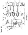
- the drive mechanism 4 mainly includes an electrically driven motor 41 (rotational drive apparatus, drive motor), a reduction gear mechanism 42 and a circuit board 43 on which a controller 5 (control means, described later) and Hall elements 6, 7, and 8 are mounted.
- the electrically driven motor 41 is attached to a case 44 fixed at the housing 21 of the sunroof apparatus 2.
- the electrically driven motor 41 includes a rotational shaft 41a extending in the case 44.
- the reduction gear mechanism 42 includes a worm gear 45 and a wheel gear 46.
- a tooth portion 46a provided along a periphery of the wheel gear 46 engages with the worm gear 45.
- the worm gear 45 is fixed at the rotational shaft 41a so as to rotate with the rotational shaft 41a of the electrically driven motor 41.
- the wheel gear 46 is rotatably supported by a support shaft 44a standing from the case 44.
- An output gear portion 46c (output member) is provided on an upper surface 46b (upper surface in Fig. 9) of the wheel gear 46.
- the transmission belt 3 connected to the shoe 23 is engaged with the output gear portion 46c.
- the shoe 23 moves so as to slide in a backward direction of the vehicle for performing an action for opening the opening portion 12 by sliding the movable panel 13 or performing an action for closing the opening portion 12 by tilting the movable panel 13.
- the electrically driven motor 41 is actuated in an inverse direction
- the shoe 23 moves so as to slide in a forward direction of the vehicle for performing an action for closing the opening portion 12 by sliding the movable panel 13 or performing an action for opening the opening portion by tilting the movable panel 13.
- the circuit board 43 is accommodated in the case 44, and covered by the cover 47.
- a Hall element 6 (first pulse signal generator) and a Hall element 7 are attached at parts of the circuit board 43 facing the rotational shaft 41a.
- a Hall element 8 (second pulse signal generator) is attached at a part of the circuit board 43 facing the wheel gear 46.
- a magnet 4 1 b is provided at a peripheral surface of the rotational shaft 4 1 a facing the Hall elements 6 and 7.
- the Hall element 6 emits a pulse when the magnet 41b passes near the Hall element 6 while the rotational shaft 41 a is rotated.
- the Hall element 7 emits a pulse when the magnet 41 b passes near the Hall element 7 while the rotational shaft 41 a is rotated.
- each of the Hall elements 6 and 7 emit a pulse every cycle of rotation of the rotational shaft 41a.
- the rotational shaft 41a can be magnetized so that the rotational shaft 41a has a magnetized portion instead of using magnets.
- an S pole magnet 81 and an N pole magnet 82 are fixed at a lower surface 46d (lower surface exhibited in Fig. 9) of the wheel gear 46, the surface facing the Hall element 8, so that the S pole magnet 81 and the N pole magnet 82 face the Hall element 8.
- the S pole magnet 81 has a thin arc shape.
- the N pole magnet 82 also has a thin arc shape.
- the S pole magnet 81 and the N pole magnet 82 are arranged on the lower surface 46d of the wheel gear 46 in series in the rotational direction of the wheel gear 46 so as to make a circular shape.
- the Hall element 8 emits one cycle of pulse at every cycle of rotation of the wheel gear 46 as the S pole magnet 81 and the N pole magnet 82 pass near the Hall element 8 while the wheel gear 46 is rotated. Then, relation of the engagement between the output gear portion 46c of the wheel gear 46 and the transmission belt 3 connected to the shoe 23 is determined so that a pulse emitted by the Hall element 8 rises in front or at the back of the position of the movable panel 13 in which the movable panel 13 makes the entirely closed condition of the opening portion 12 (entirely closed position A of the movable panel 13), specifically, so that two edges of a pulse are generated so as to sandwich the entirely closed position A of the movable panel 13 while the shoe 23 is located at the horizontal part of the long groove 24a.
- the wheel gear 46 can be magnetized so that the wheel gear 46 has a magnetized portion instead of using magnets.
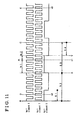
- the controller 5 controls actuations of the electrically driven motor 41 for moving the movable panel 13 in order to open and close the opening portion 12 corresponding to operations of a slide switch 15 for opening and closing operation by sliding the movable panel 13 and a tilt switch 16 for opening and closing operation by tilting the movable panel 13 operated by a user.
- the controller 5 includes a micro processor unit (MPU) 51.
- the MPU 51 is electrically connected to a battery 17 mounted on the vehicle 1 through a power source circuit 52.
- the MPU 51 is electrically connected to an ignition switch 14 of the vehicle 1 through an input interface circuit 53.
- a predetermined value of voltage is supplied to the MPU 51 from the power source circuit 52 corresponding to a signal from the ignition switch 14.
- the slide switch 15 is electrically connected to the MPU 51 through the input interface circuit 53.
- the tilt switch 16 is electrically connected to the MPU 51 through the input interface circuit 53.
- On and off signals of the slide switch 15 are transmitted to the MPU 51 corresponding to operations of the slide switch 15.
- On and off signals of the tilt switch 16 are also transmitted to the MPU 51 corresponding to operations of the tilt switch 16.
- the Hall elements 6, 7 and 8 are electrically connected to the MPU 51 through input interface circuits 54, 55 and 56 respectively.
- pulses emitted by the Hall elements 6, 7 and 8 are transmitted to the MPU 51 respectively.
- a drive circuit 58 for operating a relay utilized for supplying battery voltage to the electrically driven motor 41 for driving the electrically driven motor 41 is electrically connected to the MPU 51.
- the MPU 51 emits drive signals and stop signals to the drive circuit 58.
- the MPU 51 drives the electrically driven motor 41 in a regular direction and in an inverse direction and stops the electrically driven motor 41.
- the MPU 51 performs an action for opening the opening portion 12 by tilting the movable panel 13, an action for closing the opening portion 12 by tilting the movable panel 13, an action for opening the opening portion 12 by sliding the movable panel 13, and an action for closing the opening portion 12 by sliding the movable panel 13.
- the MPU 51 includes a counter 51a for counting pulses emitted by the Hall element 6. Further, the MPU 51 includes a counter 51b for counting pulses emitted by the Hall element 7. In addition, the MPU 51 includes another counter 51c for entirely closing the movable panel 13. Count values of the counter 51a and the counter 51 b increment respectively when the Hall elements 6 and 7 emit pulses while the shoe 23 proceeds in backward direction of the vehicle (a direction of the movable panel 13 slid for opening the opening portion 12 and a direction of the movable panel 13 tilted for closing the opening portion 12) relative to the guide rail 22.
- the count values of the counter 51 a and the counter 51b decrement respectively when the Hall elements 6 and 7 emit pulses while the shoe 23 proceeds in front direction of the vehicle (a direction of the movable panel 13 slid for closing the opening portion 12 and a direction of the movable panel 13 tilted for opening the opening portion 12) relative to the guide rail 22.
- a direction in which the shoe 23 proceeds relative to the guide rail 22 can be known by relation between phases of the pulse emitted by the Hall element 6 and the pulse emitted by the Hall element 7.
- a count value of the counter 5 1 c for entirely closing the movable panel 13 increments when the Hall element 6 emits a pulse.
- the MPU 51 grasps a sliding position of the shoe 23 relative to the guide rail 22, in other words, recognizes a position of the movable panel 13 in relation to opening and closing.
- the MPU 51 grasps a sliding direction of the shoe 23 relative to the guide rail 22 as described above, in other words, recognizes a direction of the movable panel 13 in relation to opening and closing.
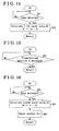
- the MPU 51 grasps a sliding position of the shoe 23 relative to the guide rail 22, in other words, recognizes a position of the movable panel 13 in relation to opening and closing, and controls the movable panel 13 so as to stop at the entirely closed position A of the opening portion 12. Specifically, the MPU 51 performs two routines: firstly, a control routine for stopping the movable panel 13 at the entirely closed position A, illustrated in Figs.
- a learning routine of the entirely closed position illustrated in Figs. 12 to 16, performed before the control routine described above.
- the learning routine is performed on the process of assembling the sunroof apparatus 2 to the vehicle 1, or on the process of closing the opening portion 12 by tilting the movable panel 13 and on the process of closing the opening portion 12 by sliding the movable panel 13.
- the learning routine performs following processes in series: firstly, a base position-searching process S1 for setting a base position B (origin) of counting pulses emitted by the Hall elements 6 and 7 respectively by the counters 51a and 51b included in the MPU 51; secondly, a first base point calculation process S2 for calculating a first count value N1 during an action of the movable panel 13 tilted for closing the opening portion 12 from when the edge of the pulse is emitted by the Hall element 8 just before the movable panel 13 achieves the entirely closed position A to when the movable panel 13 achieves the entirely closed position A; thirdly, a preparation process S3 of a second base point calculation for calculating a second count value N2 during an action of the movable panel 13 slid for closing the opening portion 12 from when the edge of the pulse is emitted by the Hall element 8 just before the movable panel 13 achieves the entirely closed position A to when the movable panel 13 achieves the entirely closed position A; thirdly, a preparation process S
- the MPU 51 actuates the electrically driven motor 41 for opening the opening portion 12 by tilting the movable panel 13 from the entirely closed position A.
- the mechanically stopped condition is detected through excessive load applied to the electrically driven motor 41, or the like, in a step S11, and values of the counters 51a and 51 b are reset in a step S12.
- a base position B is set.
- the first base point calculation process S2 will be explained with reference to Figs. 11 and 14.
- the MPU 51 actuates the electrically driven motor 41 for closing the opening portion 12 by tilting the movable panel 13 from the base position B.
- the counters 51a and 51b keep on counting the pulses respectively emitted by the Hall elements 6 and 7 from the base position B set in the step S1 described above.
- a count value X of the counter 51a at this time and a predetermined count value n1 determined for a predetermined entirely closed position A are compared in a step S22.
- the first count value N1 from when the edge of the pulse emitted by the Hall element 8 is detected to when the movable panel 13 achieves the entirely closed position A is calculated and stored in a memory (random access memory; RAM) in the MPU 51.
- the first count value N1 is calculated.
- the MPU 51 actuates the electrically driven motor 41 for continuing an action for closing the opening portion 12 by tilting the movable panel 13, and further, for continuing an action for opening the opening portion 12 by sliding the movable panel 13 over the entirely closed position A.
- the counter 51a and 51b keep on counting the pulses emitted by the Hall elements 6 and 7 respectively from the base position B set in the process S1 described above.
- the movable panel 13 is slid for opening the opening portion 12 until it is recognized, on the basis of the value of the counter 51a, that the shoe 23 is located at a predetermined position C.
- the movable panel 13 is located at the predetermined position C.
- the second base point calculation process S4 will be explained with reference to Figs. 11 and Fig. 16.
- the MPU 51 actuates the electrically driven motor 41 for opening the opening portion 12 by sliding the movable panel 13 from the predetermined position C.
- the counter 51a and 51b keep on counting the pulses emitted by the Hall element 6 and 7 respectively from the base position B set in the process S1 described above.
- a count value Y of the counter 51a at this time and a predetermined count value n 1 determined for the predetermined entirely closed position A are compared in a step S42.
- the second count value N2 from when the edge of the pulse emitted by the Hall element 8 is detected to when the movable panel 13 achieves the entirely closed position A is calculated and the second count value N2 is stored in a memory (RAM) in the MPU 51. Then, in a step S43, the counter 51c for stopping the movable panel 13 at the entirely closed position is reset. Thus, the second count value N2 is calculated.
- the MPU 51 learns the first count value N1 and the second count value N2, which are base values for stopping the movable panel 13 at the entirely closed position A.
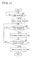
- the MPU 51 monitors pulses emitted by the Hall element 8 for judging whether an edge of the pulse is generated or not in a step S51.
- the value of the counter 51 c for stopping the movable panel at the entirely closed position is reset in a step S52. Then, the count value of the counter 51c increments when the Hall element 6 emits a pulse in a step S53 and a step S54.
- a count value of the counter 51c becomes equal to or more than the first counted value N1 or not in a step S55.
- the movable panel 13 is located at the entirely closed position A.
- an action of the movable panel 13 tilted for closing the opening portion 12 is stopped in a step S56.
- the movable panel 13 is located surely at the entirely closed position A, and as a result, the opening portion 12 becomes the entirely closed condition.
- the MPU 51 monitors pulses emitted by the Hall element 8 for judging whether an edge of the pulse is generated or not in a step S61.
- a value of the counter 51 c for stopping the movable panel 13 at the entirely closed condition is reset in a step S62. Then, the count value of the counter 51c increments when the Hall element 6 emits a pulse in a step S63 and a step S64.
- a count value of the counter 51c becomes equal to or more than the second count value N2 or not in a step S65.
- a count value of the counter 51c becomes equal to or more than the second count value N2
- it is recognized that the movable panel 13 is located at the entirely closed position A.
- a step S66 an action of the movable panel slid for closing the opening portion 12 is stopped.
- the movable panel 13 is located surely at the entirely closed position A, and as a result, the opening portion 12 becomes the entirely closed condition.
- the recognition of the entirely closed position A can be more accurate than that determined only on the basis of the value of the counter 51a counting the pulses emitted by the Hall element 6.
- the MPU 51 can recognize the entirely closed position A surely and accurately.
- the Hall element 8 emits a pulse corresponding to a rotation of the wheel gear 46 of the reduction gear mechanism 42
- plurality of base points (according to the embodiment, the two values X and Y of the counter 51a when an edge of the pulse emitted by the Hall element 8 is detected) can be set.
- the MPU 51 can be configured so as to count an edge of the pulse emitted by the Hall element 8, and the count value can be related to the opening/closing position of the movable panel 13.
- the MPU 51 recognizes values X and Y of the counter 51a when an edge of the pulse emitted by the Hall element 8 is detected, but not limited. The MPU 51 can recognizes these values as positions X, Y of the movable panel 13 in relation to opening and closing, and the values of the counter 51a can be recognized as information of positions.
- the wheel gear 46 is formed as a unit with the output gear portion 46c, a pulse emitted by the Hall element 8 corresponds to a rotation of the output gear portion 46c.
- the S pole magnet 81 and the N pole magnet 82 can be provided at the output gear portion 46c, and the Hall element 8 can be provided so as to emit a pulse corresponding to a rotation of the output gear portion 46c.
- the drive apparatus for an opening/closing body for a vehicle is applied to control of stopping the movable panel 13 at the entirely closed position A, but it is not limited to the entirely closed position A.
- the drive apparatus for an opening/closing body for a vehicle can be applied to a control of stopping the movable panel 13 at a position D in which the opening portion 12 is opened by tilting the movable panel 13 or a control of stopping the movable panel 13 at a position E for opening the opening portion 12 by sliding the movable panel 13.
- the recognition of the position D of the movable panel 13 for opening the opening portion 12 by tilting the movable panel 13 is performed by judging whether a count value of the counter 51a is equal to a predetermined value n2 or not.
- the recognition of the position E for opening the opening portion 12 by sliding the movable panel 13 is performed by judging whether a count value of the counter 51a is equal to a predetermined value n3 or not.
- a pulse signal emitted by a second pulse signal generator corresponds to a rotation of a reduction gear mechanism or an output member for moving a connection member
- a plurality of timings when the pulse signal emitted by the second pulse signal generator can be set in a whole stroke of opening/closing an opening/closing body. Accordingly, a control means can accurately recognize an opening/closing position of the opening/closing body without depending on a way of opening/closing.
Landscapes
- Engineering & Computer Science (AREA)
- Mechanical Engineering (AREA)
- Power-Operated Mechanisms For Wings (AREA)
- Transmission And Conversion Of Sensor Element Output (AREA)
Abstract
A drive apparatus for an opening/closing body (13) for a vehicle includes a drive unit
(4) including a rotational drive apparatus (41), a reduction gear mechanism (42) linked with a
rotational shaft (41a) of the rotational drive apparatus, and an output member (46c) linked
with the rotational shaft through the reduction gear mechanism and linked with the
opening/closing body through a connection member (23, 3), a first pulse signal generator (6)
provided at the drive unit and generating a first pulse signal on the basis of a rotation of the
rotational shaft, and a control means (5) for calculating an opening/closing position of the
opening/closing body on the basis of the first pulse signal emitted by the first pulse signal
generator and controlling the rotational drive apparatus corresponding to the opening/closing
position of the opening/closing body. The drive apparatus for an opening/closing body for a
vehicle is characterized in that the opening/closing apparatus further comprises a second pulse
signal generator (8) provided at the drive unit and generating a second pulse signal on the
basis of a rotation of either one of the reduction gear mechanism and the output member, and
the control means calculates an opening/closing position of the opening/closing body on the
basis of the first pulse signal emitted by the first pulse signal generator utilizing the second
pulse signal emitted by the second pulse signal generator as a base point and controls the
rotational drive apparatus corresponding to the opening/closing position of the
opening/closing body.
Description
This invention generally relates to a drive apparatus for an opening/closing body
for a vehicle. More specifically, this invention pertains to a drive apparatus for an
opening/closing apparatus for a vehicle for moving an opening/closing body of a vehicle.
As a drive apparatus for an opening/closing body such as a sunroof panel and a
sunshade panel provided at a roof of a vehicle, a roof panel and a back window panel of a
convertible, a swing door and a tail gate provided at sides or rear portion of the vehicle, a
window panel provided at a door of a vehicle, in JP2004-11322A, a conventional drive
apparatus including a rotational drive apparatus, a drive unit including a reduction gear
mechanism linked with a rotational shaft of the rotational drive apparatus and an output
member linked with the rotational shaft through a reduction gear mechanism and linked with
an opening/closing body through a connection member, a pulse signal generator provided at
the drive unit and generating a pulse signal on the basis of rotations of the rotational shaft, and
a control means for calculating a position of the opening/closing body in relation to opening
and closing on the basis of the pulse signal emitted by the pulse signal generator and for
controlling stop of the rotational drive apparatus on the basis of the position of the
opening/closing body in relation to opening and closing is described.
In addition, the drive unit includes a position-detecting means for detecting that
the connection member achieves a predetermined base position provided between the drive
unit and the connection member. When the position-detecting means detects that the
connection member achieves the base position, a calculation of position on the basis of pulse
signals generated by the pulse signal generator is corrected, and thus a predetermined
opening/closing position of the opening/closing body can be recognized more accurately.
However, in the conventional apparatus described above, the position-detecting
means detects the base position through the connection member. Accordingly, a detected
portion of the connection member detected by the position-detecting member becomes the
base position only once in a whole stroke for opening and closing the opening/closing body.
In other words, chance for detecting the base position by the position-detecting means is
obtained only once in the whole stroke for opening and closing the opening/closing body.
Therefore, depending on a width of a range of opening and closing the opening/closing body,
when the opening/closing body is opened or closed in only a range that the connection
member does not achieve the base position, the calculation of position of the opening/closing
body on the basis of pulse signals generated by the pulse signal generator cannot be corrected.
As a result, there is a danger that the control means does not recognize the predetermined
position accurately.
A need thus exists for a drive apparatus for an opening/closing body of a vehicle
in which a control means can recognize a predetermined position accurately, regardless of a
width of a range of opening and closing the opening/closing body.
According to an aspect of the present invention, a drive apparatus for an opening/closing
body (13) for a vehicle includes a drive unit (4) including a rotational drive apparatus (41), a
reduction gear mechanism (42) linked with a rotational shaft (41a) of the rotational drive
apparatus, and an output member (46c) linked with the rotational shaft through the reduction
gear mechanism and linked with the opening/closing body through a connection member (23,
3), a first pulse signal generator (6) provided at the drive unit and generating a first pulse
signal on the basis of a rotation of the rotational shaft, and a control means (5) for calculating
an opening/closing position of the opening/closing body on the basis of the first pulse signal
emitted by the first pulse signal generator and controlling the rotational drive apparatus
corresponding to the opening/closing position of the opening/closing body. The drive
apparatus for an opening/closing body for a vehicle is characterized in that the
opening/closing apparatus further comprises a second pulse signal generator (8) provided at
the drive unit and generating a second pulse signal on the basis of a rotation of either one of
the reduction gear mechanism and the output member, and the control means calculates an
opening/closing position of the opening/closing body on the basis of the first pulse signal
emitted by the first pulse signal generator utilizing the second pulse signal emitted by the
second pulse signal generator as a base point and controls the rotational drive apparatus
corresponding to the opening/closing position of the opening/closing body.
According to a further aspect of the present invention, because a pulse signal
emitted by the second pulse signal generator corresponds to a rotation of the reduction gear
mechanism or the output member for moving the connection member, a plurality of timings
when the pulse signal emitted by the second pulse signal generator can be set in a whole
stroke of opening/closing the opening/closing body. Accordingly, the control means can
accurately recognize an opening/closing position of the opening/closing body without
depending on a way of opening/closing. In addition, there is no need of providing a plurality
of second pulse signal generators. As a result, the number of parts and costs for
manufacturing are not increased.
The foregoing and additional features and characteristics of the present invention will
become more apparent from the following detailed description considered with reference to
the accompanying drawings, wherein:
An embodiment of the present invention will be explained with reference to
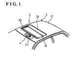
drawing figures. As illustrated in Fig. 1, a roof panel 11 of a vehicle 1 includes an opening
portion 12. A sunroof apparatus 2 including a movable panel 13 (opening/closing body) for
opening and closing the opening portion 12 is provided at the roof panel 11.
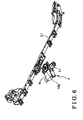
As illustrated in Fig. 2 and Fig. 3, the sunroof apparatus includes guide rails 22
provided along side ends, in other words, right and left ends, of the opening portion 12 of the
vehicle 1 and connected mutually at the front ends of the guide rails 22 by a housing 21
(illustrated in Fig. 6), a shoe 23 (connection member) slidably supported by each guide rail 22
so as to be slidable in a longitudinal direction of each guide rail 22 (fore-aft direction of the
vehicle), a lifting link 24 supported by each guide rail 22 so as to be slidable in a longitudinal
direction of each guide rail 22 and so as to swing about the front end of the lifting link 24 in a
vertical direction (up and down direction of the vehicle) and fixed to the movable panel 13,
and a drive mechanism 4 (drive unit) connected to the shoe 23 via a transmission belt 3
(connection member).
The lifting link 24 has a long shape so as to be provided along each guide rail 22.
Side surface of each lifting link 24 includes a long groove 24a extending in a longitudinal
direction and bending in upper and lower directions.
Each shoe 23 includes arm portions 23a facing mutually and sandwiching the
lifting link 24. The arm portions 23a of the shoe 23 are fitted into the long groove 24a of the
lifting link 24 so as to be movable relative to the long groove 24a of the lifting link 24.
In a configuration described above, Fig. 2 represents an entirely closed condition
in which the opening portion 12 is closed by the movable panel 13. In this condition, the arm
portion 23a of the shoe 23 is located at a horizontal portion of the long groove 24a of the
lifting link 24. In this entirely closed condition, when the shoe 23 is moved so as to slide
relative to the guide rail 22 in backward direction of the vehicle (right direction in Fig. 2), the
arm portion 23a relatively moves in the long groove 24a and the arm portion 23a is located at
a portion bended in an upper direction of the long groove 24a. As a result, the lifting link 24
swings clockwise in Fig. 2 about the front end of the lifting link 24 so that a rear end of the
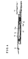
lifting link 24 moves downward. As a result, as illustrated in Fig. 4, a rear end of the movable
panel 13 moves downward, in other words, becomes a condition that the movable panel 13 is
tilted downward so that the movable panel 13 becomes slidable in backward direction of the
vehicle so as to slide the movable panel 13 for opening the opening portion 12. In this
condition, when the shoe 23 is moved relative to the guide rail 22 in backward direction of the
vehicle, the arm portion 23a becomes engaging with the rear end of the long groove 24a, and
the lifting link 24 starts to slide with the shoe 23 in a backward direction of the vehicle. As a
result, the movable panel 13 is slid so as to make an opened condition of the opening portion
12 opened by sliding the movable panel 13 (sliding action of the movable panel 13 for
opening the opening portion 12). Further, in this opened condition of the opening portion 12
opened by sliding the movable panel 13, when the shoe 23 is moved in a forward direction of
the vehicle, in other words, an inverse direction as in the action described above, the movable
panel 13 makes the entirely closed condition of the opening portion 12 (sliding action of the
movable panel 13 for closing the opening portion 12).
In the entirely closed condition illustrated in Fig. 2, when the shoe 23 is moved so
as to slide relative to the guide rail 22 in a forward direction of the vehicle (left direction in
Fig. 2), the arm portion 23a moves in and relative to the long groove 24a, and becomes to be
located at a portion bended downward of the long groove 24a. Accordingly, the lifting link
24 swings about the front end of the lifting link 24 so that the rear end of the lifting link 24 is
moved upward in a counterclockwise direction in Fig. 3. As a result, as illustrated in Fig. 5,
the rear end of the movable panel 13 moves upward for making a condition of the movable
panel 13 tilted up for opening the opening portion 12 opened by tilting the movable panel 13
upward (tilting-upward action of the movable panel 13 for opening the opening portion 12).
Further, in the condition that the movable panel 13 is tilted up, when the shoe 23 is moved so
as to slide in a backward direction of the vehicle, in other words, an inverse direction as in the
action described above, the movable panel 13 makes the entirely closed condition of the
opening portion 12 (tilting action of the movable panel 13 for closing the opening portion 12).
In addition, the sliding action of the shoe 23 is performed by driving force
generated by action of the drive mechanism 4 transmitted to the shoe 23 through the
transmission belt 3 connected to the shoe 23. In addition, configuration of connection
between the drive mechanism 4 and the transmission belt 3 will be explained in detail in later
part.
Next, the drive mechanism 4 will be explained.
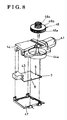
As illustrated in Fig. 6 to Fig. 9, the drive mechanism 4 mainly includes an
electrically driven motor 41 (rotational drive apparatus, drive motor), a reduction gear
mechanism 42 and a circuit board 43 on which a controller 5 (control means, described later)
and Hall elements 6, 7, and 8 are mounted.
The electrically driven motor 41 is attached to a case 44 fixed at the housing 21 of
the sunroof apparatus 2. The electrically driven motor 41 includes a rotational shaft 41a
extending in the case 44. The reduction gear mechanism 42 includes a worm gear 45 and a
wheel gear 46. A tooth portion 46a provided along a periphery of the wheel gear 46 engages
with the worm gear 45. The worm gear 45 is fixed at the rotational shaft 41a so as to rotate
with the rotational shaft 41a of the electrically driven motor 41. The wheel gear 46 is
rotatably supported by a support shaft 44a standing from the case 44. An output gear portion
46c (output member) is provided on an upper surface 46b (upper surface in Fig. 9) of the
wheel gear 46. The transmission belt 3 connected to the shoe 23 is engaged with the output
gear portion 46c.
In this configuration, when the electrically driven motor 41 is actuated, the
rotational shaft 41a is rotated. The rotation of the rotational shaft 41a is reduced through an
engagement between the worm gear 45 and the wheel gear 46. Thus, the output gear portion
46c is rotated. Because the transmission belt 3 connected to the shoe 23 engages with the
output gear portion 46c, the rotation of the output gear portion 46c moves the transmission
belt 3 in an arrow direction of Fig. 3. As a result, the shoe 23 moves so as to slide relative to
the guide rail 22. In addition, when the electrically driven motor 41 is actuated in regular
direction, the shoe 23 moves so as to slide in a backward direction of the vehicle for
performing an action for opening the opening portion 12 by sliding the movable panel 13 or
performing an action for closing the opening portion 12 by tilting the movable panel 13.
When the electrically driven motor 41 is actuated in an inverse direction, the shoe 23 moves
so as to slide in a forward direction of the vehicle for performing an action for closing the
opening portion 12 by sliding the movable panel 13 or performing an action for opening the
opening portion by tilting the movable panel 13.
The circuit board 43 is accommodated in the case 44, and covered by the cover 47.
A Hall element 6 (first pulse signal generator) and a Hall element 7 are attached at parts of the
circuit board 43 facing the rotational shaft 41a. A Hall element 8 (second pulse signal
generator) is attached at a part of the circuit board 43 facing the wheel gear 46.
A magnet 4 1 b is provided at a peripheral surface of the rotational shaft 4 1 a facing
the Hall elements 6 and 7. The Hall element 6 emits a pulse when the magnet 41b passes near
the Hall element 6 while the rotational shaft 41 a is rotated. The Hall element 7 emits a pulse
when the magnet 41 b passes near the Hall element 7 while the rotational shaft 41 a is rotated.
Thus, each of the Hall elements 6 and 7 emit a pulse every cycle of rotation of the rotational
shaft 41a. As an alternative configuration, the rotational shaft 41a can be magnetized so that
the rotational shaft 41a has a magnetized portion instead of using magnets.
As illustrated in Fig. 7 and Fig. 9, an S pole magnet 81 and an N pole magnet 82
are fixed at a lower surface 46d (lower surface exhibited in Fig. 9) of the wheel gear 46, the
surface facing the Hall element 8, so that the S pole magnet 81 and the N pole magnet 82 face
the Hall element 8. The S pole magnet 81 has a thin arc shape. The N pole magnet 82 also
has a thin arc shape. The S pole magnet 81 and the N pole magnet 82 are arranged on the
lower surface 46d of the wheel gear 46 in series in the rotational direction of the wheel gear
46 so as to make a circular shape. Then, the Hall element 8 emits one cycle of pulse at every
cycle of rotation of the wheel gear 46 as the S pole magnet 81 and the N pole magnet 82 pass
near the Hall element 8 while the wheel gear 46 is rotated. Then, relation of the engagement
between the output gear portion 46c of the wheel gear 46 and the transmission belt 3
connected to the shoe 23 is determined so that a pulse emitted by the Hall element 8 rises in
front or at the back of the position of the movable panel 13 in which the movable panel 13
makes the entirely closed condition of the opening portion 12 (entirely closed position A of
the movable panel 13), specifically, so that two edges of a pulse are generated so as to
sandwich the entirely closed position A of the movable panel 13 while the shoe 23 is located
at the horizontal part of the long groove 24a. In addition, by increasing the number of the S
pole magnets 81 and the N pole magnets 82, for example, two cycles of pulses can be emitted
at every one cycle of rotation of the wheel gear 46. As an alternative configuration, the wheel
gear 46 can be magnetized so that the wheel gear 46 has a magnetized portion instead of using
magnets.
Next, the controller 5 will be explained.
As illustrated in Fig. 10, the controller 5 controls actuations of the electrically
driven motor 41 for moving the movable panel 13 in order to open and close the opening
portion 12 corresponding to operations of a slide switch 15 for opening and closing operation
by sliding the movable panel 13 and a tilt switch 16 for opening and closing operation by
tilting the movable panel 13 operated by a user. The controller 5 includes a micro processor
unit (MPU) 51. The MPU 51 is electrically connected to a battery 17 mounted on the vehicle
1 through a power source circuit 52. The MPU 51 is electrically connected to an ignition
switch 14 of the vehicle 1 through an input interface circuit 53. A predetermined value of
voltage is supplied to the MPU 51 from the power source circuit 52 corresponding to a signal
from the ignition switch 14. Thus, the MPU 51 operable by programs becomes in operation.
The slide switch 15 is electrically connected to the MPU 51 through the input interface circuit
53. Further, the tilt switch 16 is electrically connected to the MPU 51 through the input
interface circuit 53. On and off signals of the slide switch 15 are transmitted to the MPU 51
corresponding to operations of the slide switch 15. On and off signals of the tilt switch 16 are
also transmitted to the MPU 51 corresponding to operations of the tilt switch 16. In addition,
the Hall elements 6, 7 and 8 are electrically connected to the MPU 51 through input interface
circuits 54, 55 and 56 respectively. Thus, pulses emitted by the Hall elements 6, 7 and 8 are
transmitted to the MPU 51 respectively. In addition, a drive circuit 58 for operating a relay
utilized for supplying battery voltage to the electrically driven motor 41 for driving the
electrically driven motor 41 is electrically connected to the MPU 51.
In the configuration described above, corresponding to operations of the slide
switch 15 and the tilt switch 16 operated by a user, the MPU 51 emits drive signals and stop
signals to the drive circuit 58. In addition, the MPU 51 drives the electrically driven motor 41
in a regular direction and in an inverse direction and stops the electrically driven motor 41.
Furthermore, the MPU 51 performs an action for opening the opening portion 12 by tilting the
movable panel 13, an action for closing the opening portion 12 by tilting the movable panel
13, an action for opening the opening portion 12 by sliding the movable panel 13, and an
action for closing the opening portion 12 by sliding the movable panel 13.
The MPU 51 includes a counter 51a for counting pulses emitted by the Hall
element 6. Further, the MPU 51 includes a counter 51b for counting pulses emitted by the
Hall element 7. In addition, the MPU 51 includes another counter 51c for entirely closing the
movable panel 13. Count values of the counter 51a and the counter 51 b increment
respectively when the Hall elements 6 and 7 emit pulses while the shoe 23 proceeds in
backward direction of the vehicle (a direction of the movable panel 13 slid for opening the
opening portion 12 and a direction of the movable panel 13 tilted for closing the opening
portion 12) relative to the guide rail 22. The count values of the counter 51 a and the counter
51b decrement respectively when the Hall elements 6 and 7 emit pulses while the shoe 23
proceeds in front direction of the vehicle (a direction of the movable panel 13 slid for closing
the opening portion 12 and a direction of the movable panel 13 tilted for opening the opening
portion 12) relative to the guide rail 22. Here, a direction in which the shoe 23 proceeds
relative to the guide rail 22 can be known by relation between phases of the pulse emitted by
the Hall element 6 and the pulse emitted by the Hall element 7. In addition, a count value of
the counter 5 1 c for entirely closing the movable panel 13 increments when the Hall element 6
emits a pulse. Then, on the basis of the count value of the counter 51a, the MPU 51 grasps a
sliding position of the shoe 23 relative to the guide rail 22, in other words, recognizes a
position of the movable panel 13 in relation to opening and closing. In addition, the MPU 51
grasps a sliding direction of the shoe 23 relative to the guide rail 22 as described above, in
other words, recognizes a direction of the movable panel 13 in relation to opening and
closing.
Next, an operation of the controller 5 will be explained with reference to Fig. 11.
In order that the movable panel 13 can surely makes the entirely closed condition
of the opening portion 12, in other words, in order that the movable panel 13 is stopped surely
at the entirely closed position A, the MPU 51 grasps a sliding position of the shoe 23 relative
to the guide rail 22, in other words, recognizes a position of the movable panel 13 in relation
to opening and closing, and controls the movable panel 13 so as to stop at the entirely closed
position A of the opening portion 12. Specifically, the MPU 51 performs two routines: firstly,
a control routine for stopping the movable panel 13 at the entirely closed position A,
illustrated in Figs. 17 and 18, performed in relation to an action for closing the opening
portion 12 by sliding the movable panel 13 and an action for closing the opening portion 12
by tilting the movable panel 13, and; secondly, a learning routine of the entirely closed
position, illustrated in Figs. 12 to 16, performed before the control routine described above.
In addition, the learning routine is performed on the process of assembling the sunroof
apparatus 2 to the vehicle 1, or on the process of closing the opening portion 12 by tilting the
movable panel 13 and on the process of closing the opening portion 12 by sliding the movable
panel 13.
At first, the learning routine of the entirely closed position will be explained.
As illustrated in Fig. 11 and Fig. 12, the learning routine performs following
processes in series: firstly, a base position-searching process S1 for setting a base position B
(origin) of counting pulses emitted by the Hall elements 6 and 7 respectively by the counters
51a and 51b included in the MPU 51; secondly, a first base point calculation process S2 for
calculating a first count value N1 during an action of the movable panel 13 tilted for closing
the opening portion 12 from when the edge of the pulse is emitted by the Hall element 8 just
before the movable panel 13 achieves the entirely closed position A to when the movable
panel 13 achieves the entirely closed position A; thirdly, a preparation process S3 of a second
base point calculation for calculating a second count value N2 during an action of the
movable panel 13 slid for closing the opening portion 12 from when the edge of the pulse is
emitted by the Hall element 8 just before the movable panel 13 achieves the entirely closed
position A to when the movable panel 13 achieves the entirely closed position A, and;
fourthly, a second base point calculation process S4 for calculating the second count value
N2.
The base position-searching process S1 will be explained with reference to Figs.
11 and 13.
Firstly, the MPU 51 actuates the electrically driven motor 41 for opening the
opening portion 12 by tilting the movable panel 13 from the entirely closed position A.
During this operation, when the movable panel 13 is mechanically stopped by a stopping
member (not illustrated), the mechanically stopped condition is detected through excessive
load applied to the electrically driven motor 41, or the like, in a step S11, and values of the
counters 51a and 51 b are reset in a step S12. Thus, a base position B is set.
The first base point calculation process S2 will be explained with reference to
Figs. 11 and 14.
Firstly, the MPU 51 actuates the electrically driven motor 41 for closing the
opening portion 12 by tilting the movable panel 13 from the base position B. During this
operation, the counters 51a and 51b keep on counting the pulses respectively emitted by the
Hall elements 6 and 7 from the base position B set in the step S1 described above. Then,
when an edge of the pulse emitted by the Hall element 8 is detected in a step S21, a count
value X of the counter 51a at this time and a predetermined count value n1 determined for a
predetermined entirely closed position A are compared in a step S22. Thus, the first count
value N1 from when the edge of the pulse emitted by the Hall element 8 is detected to when
the movable panel 13 achieves the entirely closed position A is calculated and stored in a
memory (random access memory; RAM) in the MPU 51. Thus, the first count value N1 is
calculated.
The preparation process S3 of a second base point-calculation will be explained
with reference to Figs. 11 and 15.
Firstly, the MPU 51 actuates the electrically driven motor 41 for continuing an
action for closing the opening portion 12 by tilting the movable panel 13, and further, for
continuing an action for opening the opening portion 12 by sliding the movable panel 13 over
the entirely closed position A. During this operation, the counter 51a and 51b keep on
counting the pulses emitted by the Hall elements 6 and 7 respectively from the base position
B set in the process S1 described above. Then, in a step S31, the movable panel 13 is slid for
opening the opening portion 12 until it is recognized, on the basis of the value of the counter
51a, that the shoe 23 is located at a predetermined position C. Thus, the movable panel 13 is
located at the predetermined position C.
The second base point calculation process S4 will be explained with reference to
Figs. 11 and Fig. 16.
Firstly, the MPU 51 actuates the electrically driven motor 41 for opening the
opening portion 12 by sliding the movable panel 13 from the predetermined position C.
During this operation, the counter 51a and 51b keep on counting the pulses emitted by the
Hall element 6 and 7 respectively from the base position B set in the process S1 described
above. Then, when an edge of a pulse emitted by the Hall element 8 is detected in a step S41,
a count value Y of the counter 51a at this time and a predetermined count value n 1 determined
for the predetermined entirely closed position A are compared in a step S42. Thus, the second
count value N2 from when the edge of the pulse emitted by the Hall element 8 is detected to
when the movable panel 13 achieves the entirely closed position A is calculated and the
second count value N2 is stored in a memory (RAM) in the MPU 51. Then, in a step S43, the
counter 51c for stopping the movable panel 13 at the entirely closed position is reset. Thus,
the second count value N2 is calculated.
As described above, the MPU 51 learns the first count value N1 and the second
count value N2, which are base values for stopping the movable panel 13 at the entirely
closed position A.
Next, the control routine for stopping the movable panel 13 at the entirely closed
position will be explained.
As illustrated in Fig. 11 and Fig. 17, when a user operates the tilt switch16 for
closing the opening portion 12 by tilting the movable panel 13 in order to make the entirely
closed condition of the opening portion 12 from the condition where the opening portion 12 is
opened by tilting the movable panel 13, the MPU 51 monitors pulses emitted by the Hall
element 8 for judging whether an edge of the pulse is generated or not in a step S51. When an
edge of the pulse emitted by the Hall element 8 is detected in the step S51, the value of the
counter 51 c for stopping the movable panel at the entirely closed position is reset in a step
S52. Then, the count value of the counter 51c increments when the Hall element 6 emits a
pulse in a step S53 and a step S54. After that, it is judged whether a count value of the
counter 51c becomes equal to or more than the first counted value N1 or not in a step S55.
When it is judged that the count value of the counter 51c becomes equal to or more than the
first count value N1, it is recognized that the movable panel 13 is located at the entirely closed
position A. Then, an action of the movable panel 13 tilted for closing the opening portion 12
is stopped in a step S56. Thus, the movable panel 13 is located surely at the entirely closed
position A, and as a result, the opening portion 12 becomes the entirely closed condition.
As illustrated in Figs. 11 and 18, when a user operates the slide switch 16 for
closing the opening portion 12 by sliding the movable panel 13 in order to make the entirely
closed condition of the opening portion 12 from the condition where the opening portion 12 is
opened by sliding the movable panel 13, the MPU 51 monitors pulses emitted by the Hall
element 8 for judging whether an edge of the pulse is generated or not in a step S61. When an
edge of the pulse emitted by the Hall element 8 is detected in the step S61, a value of the
counter 51 c for stopping the movable panel 13 at the entirely closed condition is reset in a
step S62. Then, the count value of the counter 51c increments when the Hall element 6 emits
a pulse in a step S63 and a step S64. After that, it is judged whether a count value of the
counter 51c becomes equal to or more than the second count value N2 or not in a step S65.
When it is judged that a count value of the counter 51c becomes equal to or more than the
second count value N2, it is recognized that the movable panel 13 is located at the entirely
closed position A. Then, in a step S66, an action of the movable panel slid for closing the
opening portion 12 is stopped. Thus, the movable panel 13 is located surely at the entirely
closed position A, and as a result, the opening portion 12 becomes the entirely closed
condition.
As described above, when the movable panel 13 is stopped at the entirely closed
position A, by recognizing the entirely closed position A of the movable panel 13 on the basis
of the learned and stored first count value N1 and the second count value N2, the recognition
of the entirely closed position A can be more accurate than that determined only on the basis
of the value of the counter 51a counting the pulses emitted by the Hall element 6. Thus, even
if the count value of the counter 51a is different from an actual number of pulses emitted by
the Hall element 6, the MPU 51 can recognize the entirely closed position A surely and
accurately. In addition, because the Hall element 8 emits a pulse corresponding to a rotation
of the wheel gear 46 of the reduction gear mechanism 42, plurality of base points (according
to the embodiment, the two values X and Y of the counter 51a when an edge of the pulse
emitted by the Hall element 8 is detected) can be set. In this time, the MPU 51 can be
configured so as to count an edge of the pulse emitted by the Hall element 8, and the count
value can be related to the opening/closing position of the movable panel 13. In addition, in
the embodiment, the MPU 51 recognizes values X and Y of the counter 51a when an edge of
the pulse emitted by the Hall element 8 is detected, but not limited. The MPU 51 can
recognizes these values as positions X, Y of the movable panel 13 in relation to opening and
closing, and the values of the counter 51a can be recognized as information of positions.
In the embodiment, because the wheel gear 46 is formed as a unit with the output
gear portion 46c, a pulse emitted by the Hall element 8 corresponds to a rotation of the output
gear portion 46c. However, when the output gear portion 46c is formed separately from the
wheel gear 46, the S pole magnet 81 and the N pole magnet 82 can be provided at the output
gear portion 46c, and the Hall element 8 can be provided so as to emit a pulse corresponding
to a rotation of the output gear portion 46c.
According to the embodiment of the present invention, the drive apparatus for an
opening/closing body for a vehicle is applied to control of stopping the movable panel 13 at
the entirely closed position A, but it is not limited to the entirely closed position A. For
example, the drive apparatus for an opening/closing body for a vehicle can be applied to a
control of stopping the movable panel 13 at a position D in which the opening portion 12 is
opened by tilting the movable panel 13 or a control of stopping the movable panel 13 at a
position E for opening the opening portion 12 by sliding the movable panel 13. Here,
according to this additional embodiment, the recognition of the position D of the movable
panel 13 for opening the opening portion 12 by tilting the movable panel 13 is performed by
judging whether a count value of the counter 51a is equal to a predetermined value n2 or not.
Similarly, the recognition of the position E for opening the opening portion 12 by sliding the
movable panel 13 is performed by judging whether a count value of the counter 51a is equal
to a predetermined value n3 or not.
According to an aspect of the present invention, because a pulse signal emitted by
a second pulse signal generator corresponds to a rotation of a reduction gear mechanism or an
output member for moving a connection member, a plurality of timings when the pulse signal
emitted by the second pulse signal generator can be set in a whole stroke of opening/closing
an opening/closing body. Accordingly, a control means can accurately recognize an
opening/closing position of the opening/closing body without depending on a way of
opening/closing. In addition, there is no need of providing a plurality of second pulse signal
generators. As a result, the number of parts and costs for manufacturing are not increased.
Claims (8)
- A drive apparatus for an opening/closing body (13) for a vehicle, comprising:a drive unit (4) including a rotational drive apparatus (41), a reduction gear mechanism (42) linked with a rotational shaft (41a) of the rotational drive apparatus, and an output member (46c) linked with the rotational shaft through the reduction gear mechanism and linked with the opening/closing body through a connection member (23, 3);a first pulse signal generator (6) provided at the drive unit and generating a first pulse signal on the basis of a rotation of the rotational shaft; anda control means (5) for calculating an opening/closing position of the opening/closing body on the basis of the first pulse signal emitted by the first pulse signal generator and controlling the rotational drive apparatus corresponding to the opening/closing position of the opening/closing body characterized in thatthe opening/closing apparatus further comprises a second pulse signal generator (8) provided at the drive unit and generating a second pulse signal on the basis of a rotation of either one of the reduction gear mechanism and the output member, and the control means calculates an opening/closing position of the opening/closing body on the basis of the first pulse signal emitted by the first pulse signal generator utilizing the second pulse signal emitted by the second pulse signal generator as a base point and controls the rotational drive apparatus corresponding to the opening/closing position of the opening/closing body.
- The drive apparatus for an opening/closing body for a vehicle according to claim 1, wherein
the control means includes a step of counting the first pulse signal emitted by the first pulse signal generator, a step of comparing a count value of the first pulse signal when the second pulse signal is input from the second pulse signal generator and a predetermined count value at a predetermined opening/closing position of the opening/closing body, and a step of calculating the predetermined opening/closing position on a result of the step of comparing. - The drive apparatus for an opening/closing body for a vehicle according to claim 2, wherein
the predetermined opening/closing position is determined at an entirely closed position (A) of the opening/closing body located in the middle of a whole stroke of opening/closing the opening/closing body. - The drive apparatus for an opening/closing body for a vehicle according to one of the claims 1 to 3, wherein
the rotational shaft includes a magnet (41b). - The drive apparatus for an opening/closing body for a vehicle according to one of the claims 1 to 4, wherein
the drive unit further includes a circuit board (43) on which the first pulse signal generator and the second pulse signal generator are provided. - The drive apparatus for an opening/closing body for a vehicle according to one of the claims 1 to 5, wherein
the rotational shaft is provided so as to face the first pulse signal generator. - The drive apparatus for an opening/closing body for a vehicle according to one of the claims 1 to 6, wherein
the reduction gear mechanism includes a wheel gear (46) provided so as to face the second pulse signal generator keeping a predetermined distance from the second pulse signal generator. - The drive apparatus for an opening/closing body for a vehicle according to claim 7, wherein
the wheel gear includes an S pole magnet (81) and an N pole magnet (82).
Applications Claiming Priority (2)
| Application Number | Priority Date | Filing Date | Title |
|---|---|---|---|
| JP2004180034A JP2006002441A (en) | 2004-06-17 | 2004-06-17 | Opening and closing body drive device for vehicle |
| JP2004180034 | 2004-06-17 |
Publications (1)
| Publication Number | Publication Date |
|---|---|
| EP1607257A2 true EP1607257A2 (en) | 2005-12-21 |
Family
ID=35106740
Family Applications (1)
| Application Number | Title | Priority Date | Filing Date |
|---|---|---|---|
| EP05012889A Withdrawn EP1607257A2 (en) | 2004-06-17 | 2005-06-15 | Drive apparatus for opening/closing body for vehicle |
Country Status (5)
| Country | Link |
|---|---|
| US (1) | US7015669B2 (en) |
| EP (1) | EP1607257A2 (en) |
| JP (1) | JP2006002441A (en) |
| CN (1) | CN1709738A (en) |
| TW (1) | TW200604424A (en) |
Cited By (1)
| Publication number | Priority date | Publication date | Assignee | Title |
|---|---|---|---|---|
| CN103085636A (en) * | 2011-10-28 | 2013-05-08 | 爱信精机株式会社 | Opening-and-closing Member Control Apparatus |
Families Citing this family (15)
| Publication number | Priority date | Publication date | Assignee | Title |
|---|---|---|---|---|
| JP3620836B2 (en) * | 2002-04-25 | 2005-02-16 | アイシン精機株式会社 | Opening and closing body operation mechanism |
| US7576502B2 (en) * | 2005-07-28 | 2009-08-18 | Arvinmeritor Light Vehicle Systems - France | Method and apparatus for closing a powered closure of a vehicle |
| JP4303762B2 (en) * | 2007-03-28 | 2009-07-29 | 八千代工業株式会社 | Outer slide type sunroof device |
| US8755975B2 (en) * | 2011-01-06 | 2014-06-17 | Honda Motor Co., Ltd. | Automatic vehicle door movement control system |
| JP2012144923A (en) * | 2011-01-13 | 2012-08-02 | Alps Electric Co Ltd | Power window device |
| US9031498B1 (en) | 2011-04-26 | 2015-05-12 | Sprint Communications Company L.P. | Automotive multi-generation connectivity |
| US8548532B1 (en) | 2011-09-27 | 2013-10-01 | Sprint Communications Company L.P. | Head unit to handset interface and integration |
| US9398454B1 (en) | 2012-04-24 | 2016-07-19 | Sprint Communications Company L.P. | In-car head unit wireless communication service subscription initialization |
| US8630747B2 (en) | 2012-05-14 | 2014-01-14 | Sprint Communications Company L.P. | Alternative authorization for telematics |
| US9032547B1 (en) | 2012-10-26 | 2015-05-12 | Sprint Communication Company L.P. | Provisioning vehicle based digital rights management for media delivered via phone |
| US9110774B1 (en) | 2013-03-15 | 2015-08-18 | Sprint Communications Company L.P. | System and method of utilizing driving profiles via a mobile device |
| US10489132B1 (en) | 2013-09-23 | 2019-11-26 | Sprint Communications Company L.P. | Authenticating mobile device for on board diagnostic system access |
| US9649999B1 (en) | 2015-04-28 | 2017-05-16 | Sprint Communications Company L.P. | Vehicle remote operations control |
| US9604651B1 (en) | 2015-08-05 | 2017-03-28 | Sprint Communications Company L.P. | Vehicle telematics unit communication authorization and authentication and communication service provisioning |
| CN109866584A (en) * | 2019-03-22 | 2019-06-11 | 安徽彤上智能科技有限公司 | A kind of automotive power sunroof concealed drive structure |
Citations (1)
| Publication number | Priority date | Publication date | Assignee | Title |
|---|---|---|---|---|
| JP2004011322A (en) | 2002-06-10 | 2004-01-15 | Yachiyo Industry Co Ltd | Control device for movable panel for vehicle |
Family Cites Families (7)
| Publication number | Priority date | Publication date | Assignee | Title |
|---|---|---|---|---|
| DE4423834C1 (en) * | 1994-07-07 | 1995-11-09 | Daimler Benz Ag | Drive arrangement for a retractable folding roof |
| JP3864504B2 (en) * | 1997-07-23 | 2007-01-10 | アイシン精機株式会社 | Sunroof drive |
| JPH11256920A (en) * | 1998-03-13 | 1999-09-21 | Koito Mfg Co Ltd | Power window device with safety device |
| HK1043169A1 (en) * | 1998-05-26 | 2002-09-06 | Michael Kral Joseph | Window and door closing mechanism |
| DE10053531B4 (en) * | 1999-10-29 | 2005-05-25 | Aisin Seiki K.K., Kariya | sunroof |
| EP1123826A3 (en) * | 2000-02-10 | 2009-03-04 | Mitsuba Corporation | Sunroof driving device |
| JP3917803B2 (en) * | 2000-08-02 | 2007-05-23 | アルプス電気株式会社 | Power window equipment |
-
2004
- 2004-06-17 JP JP2004180034A patent/JP2006002441A/en not_active Withdrawn
-
2005
- 2005-06-09 TW TW094119119A patent/TW200604424A/en unknown
- 2005-06-15 EP EP05012889A patent/EP1607257A2/en not_active Withdrawn
- 2005-06-16 US US11/153,335 patent/US7015669B2/en not_active Expired - Fee Related
- 2005-06-17 CN CNA2005100768360A patent/CN1709738A/en active Pending
Patent Citations (1)
| Publication number | Priority date | Publication date | Assignee | Title |
|---|---|---|---|---|
| JP2004011322A (en) | 2002-06-10 | 2004-01-15 | Yachiyo Industry Co Ltd | Control device for movable panel for vehicle |
Cited By (2)
| Publication number | Priority date | Publication date | Assignee | Title |
|---|---|---|---|---|
| CN103085636A (en) * | 2011-10-28 | 2013-05-08 | 爱信精机株式会社 | Opening-and-closing Member Control Apparatus |
| CN103085636B (en) * | 2011-10-28 | 2015-04-29 | 爱信精机株式会社 | Opening-and-closing Member Control Apparatus |
Also Published As
| Publication number | Publication date |
|---|---|
| TW200604424A (en) | 2006-02-01 |
| JP2006002441A (en) | 2006-01-05 |
| US20050280387A1 (en) | 2005-12-22 |
| US7015669B2 (en) | 2006-03-21 |
| CN1709738A (en) | 2005-12-21 |
Similar Documents
| Publication | Publication Date | Title |
|---|---|---|
| EP1607257A2 (en) | Drive apparatus for opening/closing body for vehicle | |
| JP4487588B2 (en) | Opening and closing body control device | |
| JP4595155B2 (en) | Opening / closing control device for opening covering material | |
| CN1861971B (en) | Automatic opening and closing window device | |
| CN101259826B (en) | Sunroof device for vehicle | |
| JP6001951B2 (en) | Opening / closing member control device | |
| NL2016447B1 (en) | DEVICE FOR MANUALLY OPERATING A MOTORIZED DRIVE OF A SCREEN, SUCH AS A WINDOW COVER AND METHOD FOR STORING SETTING VALUES ASSOCIATED WITH VARIOUS POSITION OF THE SCREEN | |
| JP2005351042A (en) | Opening and closing body control device | |
| JP4788114B2 (en) | Control device for opening and closing body | |
| CN102575494B (en) | Caught object detection method, setting method for caught object detection device, caught object detection device, and open/close control device | |
| JP4303762B2 (en) | Outer slide type sunroof device | |
| US10464399B2 (en) | Vehicle window opening device | |
| JP4596079B2 (en) | Opening / closing control device for opening covering material | |
| US10024095B2 (en) | Openable and closable member control apparatus | |
| JP6697953B2 (en) | Opening/closing body control system and opening/closing body control method | |
| US9376001B2 (en) | Sunroof device for a vehicle | |
| EP2338717A2 (en) | Entrapment detection apparatus for opening/closing member | |
| CN110685533A (en) | Vehicle window lifting control device | |
| JP2007224685A (en) | Open / close control device and setting method of open / close control | |
| JP2003003740A (en) | Open-close member controller and method for controlling open-close member | |
| JP2966015B2 (en) | Sunroof opening and closing control device | |
| JP2004100184A (en) | Door opening / closing control device and method | |
| CN112810416B (en) | Methods and motor control systems used in roof components | |
| JP2008069571A (en) | Opening / closing member control device and control method of opening / closing member | |
| JPH08303113A (en) | Switch structure and pinch prevention device using this switch structure |
Legal Events
| Date | Code | Title | Description |
|---|---|---|---|
| PUAI | Public reference made under article 153(3) epc to a published international application that has entered the european phase |
Free format text: ORIGINAL CODE: 0009012 |
|
| AK | Designated contracting states |
Kind code of ref document: A2 Designated state(s): AT BE BG CH CY CZ DE DK EE ES FI FR GB GR HU IE IS IT LI LT LU MC NL PL PT RO SE SI SK TR |
|
| AX | Request for extension of the european patent |
Extension state: AL BA HR LV MK YU |
|
| STAA | Information on the status of an ep patent application or granted ep patent |
Free format text: STATUS: THE APPLICATION HAS BEEN WITHDRAWN |
|
| 18W | Application withdrawn |
Effective date: 20081211 |