EP1607228A2 - Paper rotation method and apparatus - Google Patents
Paper rotation method and apparatus Download PDFInfo
- Publication number
- EP1607228A2 EP1607228A2 EP05105296A EP05105296A EP1607228A2 EP 1607228 A2 EP1607228 A2 EP 1607228A2 EP 05105296 A EP05105296 A EP 05105296A EP 05105296 A EP05105296 A EP 05105296A EP 1607228 A2 EP1607228 A2 EP 1607228A2
- Authority
- EP
- European Patent Office
- Prior art keywords
- sheet
- roller
- rollers
- printing
- controller
- Prior art date
- Legal status (The legal status is an assumption and is not a legal conclusion. Google has not performed a legal analysis and makes no representation as to the accuracy of the status listed.)
- Withdrawn
Links
Images

Classifications
-
- B—PERFORMING OPERATIONS; TRANSPORTING
- B65—CONVEYING; PACKING; STORING; HANDLING THIN OR FILAMENTARY MATERIAL
- B65H—HANDLING THIN OR FILAMENTARY MATERIAL, e.g. SHEETS, WEBS, CABLES
- B65H9/00—Registering, e.g. orientating, articles; Devices therefor
- B65H9/002—Registering, e.g. orientating, articles; Devices therefor changing orientation of sheet by only controlling movement of the forwarding means, i.e. without the use of stop or register wall
-
- B—PERFORMING OPERATIONS; TRANSPORTING
- B65—CONVEYING; PACKING; STORING; HANDLING THIN OR FILAMENTARY MATERIAL
- B65H—HANDLING THIN OR FILAMENTARY MATERIAL, e.g. SHEETS, WEBS, CABLES
- B65H2301/00—Handling processes for sheets or webs
- B65H2301/30—Orientation, displacement, position of the handled material
- B65H2301/33—Modifying, selecting, changing orientation
- B65H2301/331—Skewing, correcting skew, i.e. changing slightly orientation of material
-
- B—PERFORMING OPERATIONS; TRANSPORTING
- B65—CONVEYING; PACKING; STORING; HANDLING THIN OR FILAMENTARY MATERIAL
- B65H—HANDLING THIN OR FILAMENTARY MATERIAL, e.g. SHEETS, WEBS, CABLES
- B65H2511/00—Dimensions; Position; Numbers; Identification; Occurrences
- B65H2511/20—Location in space
- B65H2511/24—Irregularities, e.g. in orientation or skewness
-
- B—PERFORMING OPERATIONS; TRANSPORTING
- B65—CONVEYING; PACKING; STORING; HANDLING THIN OR FILAMENTARY MATERIAL
- B65H—HANDLING THIN OR FILAMENTARY MATERIAL, e.g. SHEETS, WEBS, CABLES
- B65H2513/00—Dynamic entities; Timing aspects
- B65H2513/10—Speed
Definitions
- the present invention relates to a rotator on a duplex imager that rotates a sheet following inversion.
- the front side and rear side images are usually referenced from a same edge of a sheet on which they are printed. Since many inverters invert the sheet so the leading edge (from which the front image is referenced), becomes the trailing edge and since most printers reference the current leading edge, the rear side imager lacks a reference to the image on the front side.
- Some prior art duplex imaging systems use relatively complex measurement systems to determine the position of the current trailing edge and use that edge as a reference for the printing of the rear image.
- Other prior art systems use bulky and/or complex mechanisms to rotate an inverted sheet to restore its reference edge to the lead position; one such system comprising an arm that grabs the sheet, rotates the arm 180 degrees about an end of the arm remote from the sheet and releases the sheet.
- a skewed image i.e., an image whose edges are slanted with respect to the edges of the sheet on which they are printed, is another shortcoming of prior art imagers.
- a sheet moves along a printer or copier, it may be subject to air turbulence that causes misalignment.
- a side edge of the moving sheet contacts stationary guide rails along its path so the sheet straightens prior to reaching an imaging station.
- the contact time may not be sufficient to straighten the sheet and a skewed image may result.
- US Patent RE 37,007 describes a system for de-skewing in which rollers are configured to selectively drive a sheet to correct skew.
- the rollers are all driven by a common drive mechanism and contact with the sheet is controlled by counter rollers.
- An aspect of some embodiments of the present invention relates to a rotator that rotates an inverted sheet utilizing spaced rollers.
- at least two spaced, driven rollers contact a surface of a sheet and rotate in opposite directions, causing the sheet to revolve around an axis perpendicular to the sheet, thereby reversing the leading and trailing edges.
- the rotator includes at least one counter roller that presses the sheet against at least one driven roller, thereby preventing the sheet from slipping during rotation.
- the at least one counter roller is friction driven by its friction with the moving sheet.
- the at least one counter roller has more than one degree of rotational freedom.
- counter rollers are provided for each of the driven rollers.
- the rollers are independently driven.
- An aspect of some embodiments of the present invention provides a skewed sheet correction system comprising two or more sensors spaced away from each other, the sensors being operationally linked to a controller that controls a sheet rotator.
- the two or more sensors sense a degree of skew along the leading edge of a sheet and provide signals to the controller that directs skew-correcting rotation by the rotator.
- the sheet rotator comprises at least two driven rollers spaced from each other.
- An aspect of some embodiments of the present invention provides a sheet trailing edge sensor operationally linked to a controller that controls a sheet rotator.
- the trailing edge sensor senses the trailing edge of a sheet, and directs the rotator to rotate the sheet 180 degrees, bringing the trailing edge to the lead.
- An aspect of some embodiments of the present invention provides a system for realigning grossly misaligned sheets.
- an exemplary embodiment of an inventive system comprises a guide rail aligned with a station entry and an optional sheet side offset mechanism.
- the system also includes a trajectory offset mechanism that acts on a sheet to offset the trajectory of a first side edge away from the guide rail with sufficient offset between the first side edge and the rail so that even a grossly skewed sheet does not override the rail.
- the sheet side offset mechanism presses against a second side edge causing the first side edge to contact the guide rail, thereby aligning the sheet with the station entry.
- the trajectory offset mechanism comprises at least two driven rollers, spaced away from each other, that contact the sheet surface.
- the at least two rollers rotate at different speeds to offset an edge of the sheet from the rail.
- the at least two driven rollers rotate around a point that is offset a distance from the sheet center, thereby offsetting the edge as the sheet is rotated.
- apparatus for rotating a sheet moving in a first direction comprising:
- the apparatus comprises at least one counter roller adapted to contact a second side of the sheet opposite at least one of the first and second rollers.
- the at least one counter roller is friction driven.
- the at least one counter roller has freedom of motion along at least two axes.
- the controller selectively operates the rollers in at least two modes, a first mode in which the rollers rotate with opposite senses, thereby rotating the sheet and a second mode in which the rollers operate with a same sense, thereby advancing the sheet.
- the controller is operative, in a skew correction mode, to rotate the rollers at different rates to correct skew in the sheet.
- the apparatus comprises at least one skew sensor connected to the controller, the at least one skew sensor being adapted to sense skew of the sheet.
- the controller is operative, in a skew correction mode to rotate the rollers at different rates to correct skew in the sheet.
- the apparatus includes at least one skew sensor connected to the controller, the at least one skew sensor being adapted to sense skew of the sheet.
- the apparatus includes a trailing edge sensor, the sensor sensing a trailing edge of the sheet as it moves in the given direction.
- the controller causes the rollers to rotate the sheet 180 degrees in response to said sensing, such that leading and trailing edges of the sheet are interchanged.
- the controller controls the rotation speed of the at least one first roller to differ from the rotation speed of the at least one second roller operative to offset the sheet laterally to the first direction.
- the center of the sheet as it moves in the first direction is laterally offset to the first direction from the midpoint of the rollers, such that the lateral position of the sheet with respect to a general transport direction is changed during said rotation.
- the controller causes the rollers to rotate the sheet 180 degrees, such that leading and trailing edges of the sheet are interchanged.
- alignment apparatus for laterally aligning a sheet moving in a first direction, the system comprising:
- the sheet offset mechanism comprises apparatus for rotating a sheet according to an embodiment of the invention.
- apparatus for reversing the leading and trailing edges of a sheet moving in a given direction comprising:
- the rotator comprises apparatus for rotating a sheet according to the invention.
- duplex printing apparatus comprising:
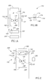
- Fig. 1A is a schematic aerial view of a sheet rotator 100 located between a turn-over drum 320 and a rear side imager 332 along a sheet conveyor 102, in accordance with an embodiment of the invention.
- the general direction of a sheet 154 is shown by an arrow 101.
- drum 320 grabs sheet 154 by reference edge 152 and turns the sheet over as indicated by arrow 310.
- Sheet 154 rolls over drum 320 so that the rear surface becomes uppermost.
- a trailing edge 150 of the sheet flips forward of reference edge 152. The trailing edge thus becomes the leading edge.
- turn over and flipping are used interchangeably to denote the act of turning over the sheet so that the positions of the surfaces of the sheet are exchanged.
- inverted or “rotated” are used to denote interchanging of the leading and trailing edges. These changes in orientation sometime occur together. Sometimes only one of the changes occurs, such as for example when the leading and trailing edges are interchanged without turning over the sheet.
- the present invention is operable with many alternative prior art flippers, including curved plate inverters or any other sheet flipping mechanism that reverses the leading and trailing edges.
- the invention is also useful for any other situation in which it is desired to reverse leading and trailing edges, without flipping the sheet.
- sheet 154 moves in direction 101 over driven rollers 110 and 120 of a rotator system 100.
- Rollers 110 and 120 are optionally overlaid by counter pressure rollers 190 and 195 respectively, to assure that rollers 110 and 120 drive sheet 154.
- the sheet is optionally driven by rollers 110 and 120 in direction 101.
- rollers 110 and 120 are rotated such that they locally drive the sheet in directions 112 and 122, causing sheet 154 to rotate in a direction 130. With 180 degrees of rotation, reference edge 152 is restored to the lead position.
- rollers 110 and 120 both rotate together in a direction to drive sheet 154 in direction 101, until trailing edge 150 is released by rollers 110 and 120.
- sheet 154 may be conveyed directly after rotation by other means for example, by conveyor 102.
- Conveyor 102 may comprise a series of rollers, one or more moving belts or any of the many known conveyor systems.
- rollers 110 and 120 are independently rotatable and/or driven.
- Fig. 1B is a side view of a portion of rotator 100, showing roller 110 positioned against sheet 154 and counter roll 190 pressing sheet 154 against roller 110, thereby preventing slippage of sheet 154 as roller 110 rotates.
- counter roller 190 is driveless, rotating as a result of friction with sheet 154.
- counter roller 190 may have two or more degrees of freedom and, for example, may have a spherical surface, to avoid slippage as sheet 154 is rotated.
- sheet 154 may be skewed, especially at the sheet moves at high speeds.
- skewing occurs prior to entering an imager, for example front side imager 330, the resultant image is skewed with respect to sheet 154.
- Fig. 2 is a schematic aerial view of a skewed edge sensor system 200 comprising sensors 210 and 220 that sense the position of leading edge 152 after inversion of the leading and trailing edges.
- sensors 220 and 210 are connected to a controller 230 that controls the rotation of independently driven rollers 110 and 120.
- controller 230 senses a skew along reference edge 152 (for example, determining that the sheet passes the sensors at different times) controller 230 directs rollers 110 and/or 120 to correct the skew.
- controller 230 directs roller 110 to briefly drive the sheet in direction 112 and/or roller 120 to briefly drive the sheet in direction 122.
- Sheet 154 rotates in direction 130 until reference edge 152 is no longer skewed.
- skewed edge sensor system 200 and rotator 100 are shown located upstream of rear side imager 330, they could be located anywhere along conveyor 102. For example they may be located prior to rear imager 332 (Fig. 1A) or prior to any station, a station comprising any sheet processor, for example inverter 320 or a sheet stacker mechanism (not shown).
- Reversing the leading and trailing edges using rollers 110 and 120 can take with the sheet located at substantially any position along the length of sheet 154. If only a single size sheet is used, then, in an embodiment of the invention, a sensor or sensors, such as sensors 210, 220 of Fig. 2 are used to sense when the leading and trailing edges should be reversed. Until the sheet reaches the sensor(s), rollers 110 and 120 both drive the sheet in direction 101, moving the sheet forward. When the leading edge is sensed by the sensor(s), the direction of rotation of one of the rollers is reversed, reversing the leading and trailing edges, as described above. For sheets of nominal length, after this rotation, the new leading edge will be substantially in the same place as the previous leading edge.
- edge 150 is in a different position formerly occupied by reference edge 152.
- the front and rear images may be imaged at different distances from reference edge 152, unless an additional step of leading edge alignment is carried out.
- the longest length to be printed is the "nominal" and sheets that are not nominal are shorter.
- Fig. 3 is an aerial view of a system utilizing a trailing edge sensor 310 located along conveyor 102 in a duplex imager, in accordance with an exemplary embodiment of the present invention.
- sheet 354 is a "short" sheet. Following reversal of the leading and trailing edges during a prior flipping of the sheet, a trailing edge 350 passes trailing edge sensor 310. The passage generates a signal that controller 230 utilizes to initiate rotation of short sheet 354 by 180 degrees, using rollers 120 and 110. Solid lines show the position of short sheet 354 and edge 350 prior to rotation while broken lines show the position of short sheet 354A and edge 350A following rotation.
- Distance 360 is the distance of the trailing edge from the rollers 110, 120, when rotation is instituted by trailing edge sensor 310.
- the edge 350 has been repositioned to position 350A, a distance 370 from the rollers. Since 360 is substantially the same as distance 370 and since the distance 360 is not dependent on the length of the sheet, position 350A will not depend on the length of the sheet.
- Fig. 4 is an aerial view of a system 400 for aligning sheets 154, even when grossly misaligned.
- System 100 comprises a trajectory offset mechanism 100 and an alignment mechanism 450.
- Alignment mechanism 450 comprises a guide 140 aligned with imager 332, and a sheet transverse offset mechanism 448, which pushes sheet 154 against guide rail, so that the sheet enters imager 332 at a correct transverse (to motion direction 101) position.
- the inventors have found that to facilitate transverse alignment of the sheet, the sheet should be at least some minimum distance (designated as 446 on Fig. 4) from guide 140. When this distance is too small, there is a tendency for the sheet to override guide 140 or be otherwise unaligned. Such lack of alignment can cause jamming of sheet 154 in imager 332 or improper placement of images on sheet 154.
- trajectory offset mechanism 100 acts on sheet 154 to offset a first side edge 444 from guide rail 140 by an offset distance 446.
- offset mechanism 100 creates sufficient offset distance 446 between edge 444 and rail 140 so that even a grossly skewed sheet is properly positioned.
- sheet side offset mechanism 448 presses against side 402 of sheet 154, causing side 444 of the sheet to contact guide rail 140, and to be aligned with guide rail 140 and also with imager 332.
- the midpoint between rollers 110 and 120 may not align with the midpoint of sheet 154 as it enters these rollers.
- sheet 154 is offset laterally to the general direction of motion 101.
- the rollers can be made to rotate at different rotation rates, such that the sheet rotates about a point that is not at the midpoint between rollers 110 and 120. This will also cause transverse offset of the sheet.
- Mechanism 100 can also be used to provide offset, without inverting leading and trailing edges. For example, if one of the rollers is rotated at a speed that is faster than the speed of the other roller, the sheet will be skewed. If the sheet is driven for a period of time in the direction of the skewed leading edge and then deskewed, an offset in the sheet will be generated.
- transverse sheet offset and alignment can be produced anywhere in the paper path, when needed to provide transverse sheet alignment.
- other methods of lateral moving of the sheet may be implementing prior to side alignment. Such methods may include physical lateral transport of the sheet and may include methods as are known in the art.
- embodiments of the invention may incorporate some but not all features of the above exemplary embodiments and may include combinations of features from different embodiments.
- the terms “comprise” or “include” and their conjugations shall mean “including but not necessarily limited to.”
Landscapes
- Registering Or Overturning Sheets (AREA)
- Controlling Sheets Or Webs (AREA)
- Delivering By Means Of Belts And Rollers (AREA)
Abstract
Description
Claims (19)
- Apparatus for rotating a sheet moving in a first direction, the rotator comprising:at least one first roller that rotates against a sheet first side, the at least one first roller having a first drive;at least one second roller that rotates against the sheet first side, the at least one second roller having a second drive that is capable of rotating the second roller independently of the first roller, the second roller being spaced a distance from the at least one first roller in a direction perpendicular to the first direction; anda controller that controls the first and second drives to rotate the sheet around an axis substantially perpendicular to the plane of the sheet.
- Apparatus according to claim 1 including at least one counter roller adapted to contact a second side of the sheet opposite at least one of the first and second rollers.
- Apparatus according to claim 2 in which the at least one counter roller is friction driven.
- Apparatus according to claim 2 or claim 3 in which the at least one counter roller has freedom of motion along at least two axes.
- Apparatus according to any of the preceding claims wherein the controller selectively operates the rollers in at least two modes, a first mode in which the rollers rotate with opposite senses, thereby rotating the sheet and a second mode in which the rollers operate with a same sense, thereby advancing the sheet.
- Apparatus according to any of the preceding claims, wherein the controller is operative, in a skew correction mode, to rotate the rollers at different rates to correct skew in the sheet.
- Apparatus according to claim 6, including at least one skew sensor connected to the controller, the at least one skew sensor being adapted to sense skew of the sheet.
- Apparatus according to any of the preceding claims, including a trailing edge sensor, the sensor sensing a trailing edge of the sheet as it moves in the given direction.
- Apparatus according to claim 8, in which the controller causes the rollers to rotate the sheet 180 degrees in response to said sensing, such that leading and trailing edges of the sheet are interchanged.
- Apparatus according to any of the preceding claims, wherein the controller controls the rotation speed of the at least one first roller to differ from the rotation speed of the at least one second roller operative to offset the sheet laterally to the first direction.
- Apparatus according to any of claim 1-9 claims, wherein the center of the sheet as it moves in the first direction is laterally offset to the first direction from the midpoint of the rollers, such that the lateral position of the sheet with respect to a general transport direction is changed during said rotation.
- Apparatus according to any of the preceding claims, in which the controller causes the rollers to rotate the sheet 180 degrees, such that leading and trailing edges of the sheet are interchanged.
- Alignment apparatus for laterally aligning a sheet moving in a first direction, the system comprising:an alignment surface, defining a side boundary;a sheet edge offset mechanism that offsets a sheet so that it is further from the rail; andan alignment mechanism operative to press the side edge of the sheet against the alignment surface so the sheet side edge substantially aligns with the side boundary.
- Alignment according to claim 13 wherein the sheet offset mechanism comprises apparatus for rotating a sheet according to claim 10.
- Alignment apparatus according to claim 13 wherein the sheet offset mechanism comprises apparatus for rotating a sheet according to claim 11.
- Apparatus for reversing the leading and trailing edges of a sheet moving in a given direction, comprising:at least one trailing edge sensor that determines the position of a trailing edge of a sheet traveling along a sheet conveyor;a rotator that rotates a sheet 180 degrees; anda controller that receives signals from the at least one trailing edge sensor and signals the rotator to rotate the sheet responsive to the passage of the sheet trailing edge.
- Apparatus according to claim 16, wherein the rotator comprises apparatus according to any of claims 1-15.
- Duplex printing apparatus comprising:a first printing engine;a second printing engine;a sheet transport system that transports a sheet from the first printing engine after printing on a first side thereof to the second printing engine for printing on the second side, the sheet transport system comprising:a sheet turner which turns over the sheet while exchanging the leading and tailing edges thereof; andapparatus according to claim 12.
- Duplex printing apparatus comprising:a first printing engine;a second printing engine;a sheet transport system that transports a sheet from the first printing engine after printing on a first side thereof to the second printing engine for printing on the second side, the sheet transport system comprising:a sheet turner which turns over the sheet while exchanging the leading and tailing edges thereof; andapparatus according to claim 13-16.
Applications Claiming Priority (2)
| Application Number | Priority Date | Filing Date | Title |
|---|---|---|---|
| US870140 | 2001-05-30 | ||
| US10/870,140 US7766325B2 (en) | 2004-06-16 | 2004-06-16 | Paper rotation method and apparatus |
Publications (2)
| Publication Number | Publication Date |
|---|---|
| EP1607228A2 true EP1607228A2 (en) | 2005-12-21 |
| EP1607228A3 EP1607228A3 (en) | 2006-02-22 |
Family
ID=34940180
Family Applications (1)
| Application Number | Title | Priority Date | Filing Date |
|---|---|---|---|
| EP05105296A Withdrawn EP1607228A3 (en) | 2004-06-16 | 2005-06-16 | Paper rotation method and apparatus |
Country Status (3)
| Country | Link |
|---|---|
| US (1) | US7766325B2 (en) |
| EP (1) | EP1607228A3 (en) |
| JP (1) | JP4108090B2 (en) |
Cited By (2)
| Publication number | Priority date | Publication date | Assignee | Title |
|---|---|---|---|---|
| EP2439158A1 (en) * | 2010-04-28 | 2012-04-11 | Canon Kabushiki Kaisha | Sheet conveyance apparatus and recording apparatus |
| CH706657A1 (en) * | 2012-06-29 | 2013-12-31 | Kern Ag | Device for turning flat sheet- or film-like products or a batch. |
Families Citing this family (4)
| Publication number | Priority date | Publication date | Assignee | Title |
|---|---|---|---|---|
| JP2010208834A (en) * | 2009-03-12 | 2010-09-24 | Konica Minolta Business Technologies Inc | Double-sided image forming device |
| DE102009058087A1 (en) * | 2009-12-14 | 2011-06-16 | Krones Ag | Device for treating containers with combined format part and installation detection |
| US9384637B2 (en) * | 2013-03-15 | 2016-07-05 | Diebold Self-Service Systems, Division Of Diebold, Incorporated | Picker for use with an automated banking machine |
| US10569980B2 (en) | 2015-12-08 | 2020-02-25 | Hewlett-Packard Development Company, L.P. | Media alignment calibration |
Family Cites Families (36)
| Publication number | Priority date | Publication date | Assignee | Title |
|---|---|---|---|---|
| JPS5910958A (en) | 1982-07-12 | 1984-01-20 | Canon Inc | double-sided recording device |
| JPS60244740A (en) | 1984-05-19 | 1985-12-04 | Fuji Xerox Co Ltd | Copying machine |
| JPS60258037A (en) | 1984-05-31 | 1985-12-19 | Fuji Xerox Co Ltd | Paper turning and transporting apparatus |
| JPS62134283A (en) * | 1985-12-09 | 1987-06-17 | Matsushita Electric Ind Co Ltd | Printer paper position correction method |
| JPS62275951A (en) * | 1986-05-20 | 1987-11-30 | Fujitsu Ltd | Bankbook reversing device for bankbook entering machine |
| US4971304A (en) | 1986-12-10 | 1990-11-20 | Xerox Corporation | Apparatus and method for combined deskewing and side registering |
| DE59010393D1 (en) * | 1989-12-07 | 1996-08-01 | Mars Inc | Device for aligning sheets |
| US5090683A (en) * | 1990-07-31 | 1992-02-25 | Xerox Corporation | Electronic sheet rotator with deskew, using single variable speed roller |
| JP2866176B2 (en) * | 1990-09-26 | 1999-03-08 | 株式会社リコー | Seat direction control device |
| US5172907A (en) * | 1991-05-10 | 1992-12-22 | Moore Business Forms, Inc. | Compensation for skewing of documents during a rotation through a finite angle |
| JPH04339679A (en) | 1991-05-17 | 1992-11-26 | Minolta Camera Co Ltd | Recorder |
| US5317377A (en) * | 1991-09-27 | 1994-05-31 | Xerox Corporation | Inverter apparatus capable of inverting A3 or 11×17" sheets |
| US5169140A (en) | 1991-11-25 | 1992-12-08 | Xerox Corporation | Method and apparatus for deskewing and side registering a sheet |
| US5261655A (en) * | 1992-12-28 | 1993-11-16 | Xerox Corporation | Disk stacker with intermittent corrugation assistance for small sheets |
| US5382013A (en) * | 1993-10-12 | 1995-01-17 | Xerox Corporation | Clutch driven inverter shaft |
| JPH07112852A (en) | 1993-10-15 | 1995-05-02 | Fuji Xerox Co Ltd | Sheet turning device |
| JP3165583B2 (en) | 1994-04-27 | 2001-05-14 | シャープ株式会社 | Double-sided image forming apparatus and reversing sheet feeder |
| US5374049A (en) * | 1994-05-27 | 1994-12-20 | Xerox Corporation | Compact inverter |
| US5449164A (en) * | 1994-08-29 | 1995-09-12 | Xerox Corporation | Sheet inverter apparatus |
| US5725211A (en) * | 1995-08-28 | 1998-03-10 | Xerox Corporation | Method and apparatus for registering images on the front and the back of a single sheet of paper |
| FR2746084B1 (en) | 1996-03-13 | 1998-05-07 | DEVICE FOR ROTATING SHEETS ON A ROLLER CONVEYOR | |
| US5794176A (en) * | 1996-09-24 | 1998-08-11 | Xerox Corporation | Adaptive electronic registration system |
| JP3186618B2 (en) * | 1996-12-12 | 2001-07-11 | 富士ゼロックス株式会社 | Paper aligning apparatus and image forming apparatus having the same |
| US6059284A (en) * | 1997-01-21 | 2000-05-09 | Xerox Corporation | Process, lateral and skew sheet positioning apparatus and method |
| US6269995B1 (en) * | 1998-04-29 | 2001-08-07 | Gerber Scientific Products, Inc. | Friction drive apparatus for strip material |
| JP3607531B2 (en) * | 1999-05-28 | 2005-01-05 | シャープ株式会社 | Charging device |
| US6241236B1 (en) * | 1999-12-01 | 2001-06-05 | Hewlett-Packard Company | Automated sheet delivery to selected paths using reversible crenellated roller |
| US6341777B1 (en) * | 2000-03-02 | 2002-01-29 | Xerox Corporation | Multiple-position idler roller |
| JP2002087689A (en) * | 2000-09-19 | 2002-03-27 | Fujitsu Ltd | Image forming apparatus, network-compatible image forming apparatus, and method therefor |
| JP3719929B2 (en) * | 2000-11-29 | 2005-11-24 | 株式会社沖データ | Paper transport device |
| US6419222B1 (en) * | 2000-12-12 | 2002-07-16 | Xerox Corporation | Sheet inverting apparatus and method |
| US6578844B2 (en) * | 2001-04-10 | 2003-06-17 | Xerox Corporation | Sheet feeder |
| CA2445189C (en) | 2001-06-21 | 2009-02-17 | Lilly Icos Llc | Carboline derivatives as pdev inhibitors |
| JP2003118887A (en) | 2001-10-19 | 2003-04-23 | Fujitsu Ltd | 180 degree turn device |
| US6920307B2 (en) * | 2003-04-25 | 2005-07-19 | Xerox Corporation | Systems and methods for simplex and duplex image on paper registration |
| JP4133943B2 (en) * | 2004-06-28 | 2008-08-13 | 住友建機製造株式会社 | Pressure sensor failure detection device |
-
2004
- 2004-06-16 US US10/870,140 patent/US7766325B2/en active Active
-
2005
- 2005-06-15 JP JP2005174823A patent/JP4108090B2/en not_active Expired - Fee Related
- 2005-06-16 EP EP05105296A patent/EP1607228A3/en not_active Withdrawn
Cited By (3)
| Publication number | Priority date | Publication date | Assignee | Title |
|---|---|---|---|---|
| EP2439158A1 (en) * | 2010-04-28 | 2012-04-11 | Canon Kabushiki Kaisha | Sheet conveyance apparatus and recording apparatus |
| US8585047B2 (en) | 2010-04-28 | 2013-11-19 | Canon Kabushiki Kaisha | Sheet conveyance apparatus and recording apparatus |
| CH706657A1 (en) * | 2012-06-29 | 2013-12-31 | Kern Ag | Device for turning flat sheet- or film-like products or a batch. |
Also Published As
| Publication number | Publication date |
|---|---|
| US7766325B2 (en) | 2010-08-03 |
| US20050280200A1 (en) | 2005-12-22 |
| EP1607228A3 (en) | 2006-02-22 |
| JP2006008412A (en) | 2006-01-12 |
| JP4108090B2 (en) | 2008-06-25 |
Similar Documents
| Publication | Publication Date | Title |
|---|---|---|
| JP4921853B2 (en) | Skew and lateral offset adjustment method and system | |
| US7258340B2 (en) | Sheet registration within a media inverter | |
| US5169140A (en) | Method and apparatus for deskewing and side registering a sheet | |
| US7631867B2 (en) | Moving carriage lateral registration system | |
| JP2552311B2 (en) | Sheet skew correction and side alignment method | |
| JP3769913B2 (en) | Sheet alignment apparatus and image forming apparatus provided with the same | |
| US5322273A (en) | Sheet registration mechanism | |
| US7472905B2 (en) | Sheet conveying apparatus, image forming apparatus and image reading apparatus | |
| JP2941851B2 (en) | Paper rotation mechanism | |
| JP2731963B2 (en) | Paper attitude control device and printer | |
| US8297616B2 (en) | Adjustable idler rollers for lateral registration | |
| JPH05201587A (en) | Device to remove skew on sheet and adjust side position | |
| JP2939209B2 (en) | Printing apparatus having an alignment station for printing on both sides of an aligned receiving sheet | |
| US7766325B2 (en) | Paper rotation method and apparatus | |
| JP4132778B2 (en) | Long receiver alignment apparatus and method, and use of drive assembly | |
| JPS6151445A (en) | Sheet matching device | |
| JPH0789645A (en) | Paper width direction correction mechanism of paper supply device | |
| JP2003020137A (en) | Paper correction device | |
| JP3513351B2 (en) | Image forming device | |
| JPH0445071A (en) | Duplex printer | |
| JPH0612934Y2 (en) | Paper skew correction device | |
| JPH05193788A (en) | Sheet conveyance correction device | |
| JPH04292355A (en) | Sheet orientation control device | |
| JPS62161679A (en) | Sheet transfer device | |
| JP2002265098A (en) | Sheet transport device |
Legal Events
| Date | Code | Title | Description |
|---|---|---|---|
| PUAI | Public reference made under article 153(3) epc to a published international application that has entered the european phase |
Free format text: ORIGINAL CODE: 0009012 |
|
| AK | Designated contracting states |
Kind code of ref document: A2 Designated state(s): AT BE BG CH CY CZ DE DK EE ES FI FR GB GR HU IE IS IT LI LT LU MC NL PL PT RO SE SI SK TR |
|
| AX | Request for extension of the european patent |
Extension state: AL BA HR LV MK YU |
|
| PUAL | Search report despatched |
Free format text: ORIGINAL CODE: 0009013 |
|
| AK | Designated contracting states |
Kind code of ref document: A3 Designated state(s): AT BE BG CH CY CZ DE DK EE ES FI FR GB GR HU IE IS IT LI LT LU MC NL PL PT RO SE SI SK TR |
|
| AX | Request for extension of the european patent |
Extension state: AL BA HR LV MK YU |
|
| AKX | Designation fees paid | ||
| REG | Reference to a national code |
Ref country code: DE Ref legal event code: 8566 |
|
| STAA | Information on the status of an ep patent application or granted ep patent |
Free format text: STATUS: THE APPLICATION IS DEEMED TO BE WITHDRAWN |
|
| 18D | Application deemed to be withdrawn |
Effective date: 20060823 |