TECHNICAL FIELD
The present invention relates to a drive apparatus for
an injection molding machine, an injection apparatus, and a
mold clamping apparatus.
BACKGROUND ART
Conventionally, hydraulic-type and electric-motor-type
drive apparatus have been used for generating thrust force in
various mechanical apparatus.
In a molding machine, which is one type of mechanical
apparatus; for example, an injection molding machine, a resin
is melted within a heating cylinder through application of
heat; the thus-molten resin is injected under high pressure
into a cavity of a mold apparatus so as to fill the cavity;
and the resin within the cavity is cooled to set, thereby
yielding a molded article.
The injection molding machine has a mold apparatus, a
mold claming apparatus, and an injection apparatus. The mold
apparatus includes a stationary mold and a movable mold. The
mold clamping apparatus includes a stationary platen to which
the stationary mold is attached, a movable platen to which
the movable mold is attached, and a mold clamping mechanism.
The mold clamping mechanism is activated so as to cause the
movable platen and the movable mold to advance and retreat,
whereby the mold apparatus can perform mold closing, mold
clamping, and mold opening. The injection apparatus includes
a heating cylinder and a screw, which is disposed within the
heating cylinder rotatably and in a manner capable of
advancing and retreating. By means of causing the screw to
advance, the resin is injected into the cavity of the mold
apparatus from an injection nozzle attached to an end of the
heating cylinder so as to fill the cavity.
In some cases, the injection apparatus uses a
hydraulic-type or electric-motor-type drive apparatus for
rotating and causing the screw to advance and retreat.
In the hydraulic-type drive apparatus, an injection
cylinder is disposed behind a screw, and hydraulic pressure
is applied to the hydraulic chamber of the injection cylinder
so as to cause a piston connected to the screw to advance and
retreat, whereby the screw can be caused to advance and
retreat. Also, a hydraulic motor is disposed behind the
injection cylinder. An output shaft of the hydraulic motor
is connected to the piston. By means of driving the
hydraulic motor, the screw can be rotated.
In the electric-motor-type drive apparatus, a pressure
plate, which supports a screw such that the screw can rotate,
is disposed in a manner capable of advancing and retreating
in relation to a front plate that supports a heating
cylinder; and, by means of driving an electric metering motor
attached to the pressure plate, the screw can be rotated. A
ball screw is disposed between the pressure plate and an
electric injection motor. By means of driving the injection
motor and converting rotary motion to rectilinear motion by
means of the ball screw, the screw can be caused to advance
and retreat.
In the hydraulic-type drive apparatus, the hydraulic
motor for rotating the screw is disposed on a rotational
shaft of the screw, so that the moment of inertia can be
reduced. By contrast, in the electric-motor-type drive
apparatus, the metering motor for rotating the screw cannot
be disposed on the rotational axis of the screw, so that the
moment of inertia cannot be reduced. Accordingly, the
electric-motor-type drive apparatus fails to exhibit high-speed
performance, high responsiveness, and high control
accuracy.
In order to cope with the above problems, an injection
apparatus that uses a linear motor as a drive apparatus can
be conceived. In the injection apparatus, the linear motor
includes a movable element having a permanent magnet, and a
stationary element having coils. Supply of predetermined
current to the stationary element causes the movable element
to advance and retreat, thereby causing the screw to advance
and retreat. In this case, magnetic poles of the permanent
magnet are arranged such that N poles and S poles alternate,
and the coils are wound in a manner corresponding to the
magnetic poles. Accordingly, the drive apparatus can exhibit
high-speed performance, high responsiveness, and high control
accuracy.
In some cases, the mold clamping apparatus also uses a
hydraulic-type or electric-motor-type drive apparatus.
In the hydraulic-type drive apparatus, a mold-clamping
cylinder is disposed behind a movable platen, and hydraulic
pressure is applied to the hydraulic chamber of the mold-clamping
cylinder, thereby causing the movable platen to
advance and retreat.
In the electric-motor-type drive apparatus, an electric
mold-clamping motor, which is attached to a toggle support
disposed behind a movable platen, is activated, and a ball
screw converts rotary motion to rectilinear motion so as to
cause a crosshead to advance and retreat, thereby causing the
movable platen, via a toggle mechanism, to advance and
retreat.
However, in the case of the hydraulic-type drive
apparatus, in order to apply hydraulic pressure to the
hydraulic chamber of the mold-clamping cylinder, a hydraulic
circuit must be disposed for supplying the hydraulic chamber
oil discharged from a hydraulic pump. In the case of the
electric-motor-type drive apparatus, after rotary motion
generated through drive of the mold-clamping motor is
converted to rectilinear motion, a mold-clamping force must
be generated by means of the toggle mechanism. The drive
apparatus of either type fails to exhibit high-speed
performance, high responsiveness, and high control accuracy.
In order to cope with the above problems, use of a
linear motor as a drive apparatus is conceived. In the mold-clamping
apparatus, the linear motor includes a movable
element having a permanent magnet, and a stationary element
having coils. Supply of predetermined current to the
stationary element causes the movable element to advance and
retreat, thereby causing the crosshead to advance and retreat
and thus causing the movable platen to advance and retreat.
Also, in this case, magnetic poles of the permanent magnet
are arranged such that N poles and S poles alternate, and the
coils are wound in a manner corresponding to the magnetic
poles. Accordingly, the drive apparatus can exhibit high-speed
performance, high responsiveness, and high control
accuracy.
However, since the linear motor does not have a
decelerating mechanism, use of the linear motor as the
conventional drive apparatus; i.e., use of the linear motor
as a drive apparatus for an injection molding machine, which
is a high-load mechanical apparatus, requires an increase in
the capacity of the linear motor in order to generate a large
thrust force and to provide short-cycled continuous drive.
The capacity of the linear motor can be increased by
increasing the area of the permanent magnet used in the
linear motor. However, since the linear motor generally
assumes a flat shape, increasing the area of the permanent
magnet increases the size of the linear motor, resulting in
an increase in not only the size of the drive apparatus, but
also the cost of the drive apparatus. Also, when the area of
the permanent magnet is increased, the weight of the movable
element increases accordingly, resulting in a failure for the
drive apparatus to exhibit high-speed performance and high
responsiveness.
In the case where the linear motor is used in the
injection apparatus, since the linear motor for effecting
injection and the metering motor are disposed adjacent to
each other on the same straight line, the axial dimension of
the injection apparatus increases, resulting in an increase
in the size of the injection apparatus.
An object of the present invention is to solve the
above-mentioned problems in the conventional drive apparatus
and to provide a drive apparatus for an injection molding
machine which can generate a large thrust force, can provide
short-cycled continuous drive, and can be reduced in size and
cost, as well as an injection apparatus and a mold-clamping
apparatus.
DISCLOSURE OF THE INVENTION
To achieve the above object, a drive apparatus for an
injection molding machine of the present invention is
characterized by comprising a housing; a tubular linear motor
comprising a movable element disposed within the housing in a
manner capable of advancing and retreating, and a stationary
element attached to the housing, the linear motor serving as
a first drive section; a member-to-be-driven which is
advanced and retreated together with the movable element
through drive of the linear motor; and a second drive section
attached to the housing and disposed such that at least a
portion of the second drive section overlaps the linear motor
along an axial direction.
In this case, since the movable element and the
stationary element constitute the tubular linear motor, the
area of a permanent magnet of the movable element can be
sufficiently increased by merely a slight increase in a
radial dimension. Accordingly, since the capacity of the
linear motor can be increased, the linear motor can generate
a large thrust force and can provide short-cycled continuous
drive. As a result, the drive apparatus can be mounted in a
high-load mechanical apparatus, such as an injection molding
machine.
Since the second drive section is disposed such that at
least a portion of the second drive section overlaps the
linear motor along the axial direction, the size of the drive
apparatus can be reduced, and the cost of the drive apparatus
can be reduced.
Since the stationary element and the second drive
section are attached to the housing, when the linear motor is
activated, the movable element moves, whereas the second
drive section remains stationary. Accordingly, the weight of
a movable portion of the drive apparatus is reduced, so that
the moment of inertia can be reduced. As a result, the drive
apparatus can be further enhanced in terms of high-speed
performance, high responsiveness, and high control accuracy.
BRIEF DESCRIPTION OF THE DRAWINGS
FIG. 1 is a sectional view of a drive apparatus
according to a first embodiment of the present invention; FIG.
2 is a sectional view of a drive apparatus according to a
second embodiment of the present invention; FIG. 3 is a
sectional view of a drive apparatus according to a third
embodiment of the present invention; FIG. 4 is a sectional
view of a drive apparatus according to a fourth embodiment of
the present invention; FIG. 5 is a sectional view of a drive
apparatus according to a fifth embodiment of the present
invention; FIG. 6 is a sectional view of a drive apparatus
according to a sixth embodiment of the present invention; FIG.
7 is a sectional view of a drive apparatus according to a
seventh embodiment of the present invention; FIG. 8 is a
cross-sectional view of a drive apparatus according to an
eighth embodiment of the present invention; FIG. 9 is a
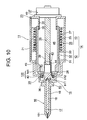
sectional view taken along line X―X of FIG. 8; FIG. 10 is a
sectional view of an injection apparatus according to a ninth
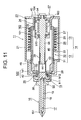
embodiment of the present invention; FIG. 11 is a sectional
view of an injection apparatus according to a tenth
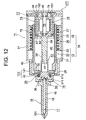
embodiment of the present invention; FIG. 12 is a sectional
view of an injection apparatus according to an eleventh
embodiment of the present invention; FIG. 13 is a front view
of a mold apparatus and a mold clamping apparatus according
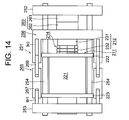
to a twelfth embodiment of the present invention; FIG. 14 is
a plan view of the mold apparatus and the mold clamping
apparatus according to the twelfth embodiment; FIG. 15 is a
sectional view showing a mold clamped condition of the mold
apparatus according to the twelfth embodiment; FIG. 16 is a
front view showing a mold open condition of the mold
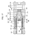
apparatus according to the twelfth embodiment; FIG. 17 is a
sectional view showing a mold clamped condition of a mold
apparatus according to a thirteenth embodiment of the present
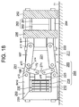
invention; FIG. 18 is a front view of a mold apparatus and a
mold clamping apparatus according to a fourteenth embodiment
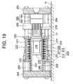
of the present invention; and FIG. 19 is a sectional view
showing a mold clamped condition of the mold apparatus
according to the fourteenth embodiment.
BEST MODE FOR CARRYING OUT THE INVENTION
The embodiments of the present invention will next be
described in detail with reference to the drawings.
FIG. 1 is a sectional view of a drive apparatus
according to a first embodiment of the present invention. In
this case, there is described a drive apparatus mounted in a
molding machine, which is one type of mechanical apparatus;
for example, an injection molding machine.
In the drawing, reference numeral 11 denotes a
cylindrical housing; reference numeral 12 denotes a
cylindrical, movable element disposed within the housing 11
in a manner capable of axially advancing and retreating
(moving in the left-right direction in the drawing);
reference numeral 13 denotes a cylindrical stationary element
attached to the inner circumferential surface of the housing
11; and reference numeral 15 denotes a member-to-be-driven,
which is disposed in a rotatable relationship to the movable
element 12 via a bearing b1 and in a manner capable of
advancing and retreating together with the movable element 12.
An unillustrated movable member is disposed ahead (leftward
in the drawing) of the member-to-be-driven 15 in such a
manner as to be rotatable and capable of advancing and
retreating. The movable element 12 and the stationary
element 13 constitute a tubular, in the present embodiment,
cylindrical linear motor 14, which serves as a first drive
section.
The housing 11 includes a cylindrically tubular portion
21; an annular front plate 22 attached to the front end (left
end in the drawing) of the tubular portion 21; and an annular
rear plate 23 attached to the rear end (right end in the
drawing) of the tubular portion 21. The stationary element
13 is attached to the tubular portion 21 over a predetermined,
substantially central range along the axial direction. The
stationary element 13 includes a core 26 having a plurality
of magnetic-pole teeth 25 formed in a radially inward
projecting condition and at predetermined pitch spacings, and
coils 27 wound on the corresponding magnetic-pole teeth 25.
The core 26 and the coil 27 constitute a stator. The
magnetic-pole teeth 25 are formed in parallel with one
another and along the circumferential direction of the core
26.
The movable element 12 includes a cylindrical core 31,
which is disposed radially inward of the stationary element
13, and a permanent magnet 32, which is disposed on the outer
circumferential surface of the core 31 and over a
predetermined axial range; specifically, a distance of the
axial length of the core 26 plus the stroke of the member-to-be-driven
15. The permanent magnet 32 is magnetized such
that magnetic poles 33 serving as N pole and magnetic poles
33 serving as S pole are alternately formed at the same pitch
spacings as those of the magnetic-pole teeth 25. The
magnetic poles 33 are formed in parallel with one another and
along the circumferential direction of the core 31. The core
26 and the coils 27 constitute a first drive element, and the
permanent magnet 32 constitutes a second drive element.
In order to support the movable element 12 in an
axially movable relationship to the housing 11, unillustrated
guide rails, which serve as guide members, are disposed in an
axially extending manner on the housing 11 at
circumferentially predetermined positions. The movable
element 12 is caused to move along the guide rails. A
tubular support portion 34 is formed on the rear plate 23 in
a manner projecting frontward from the inner circumferential
edge of the rear plate 23 by a length equal to the stroke of
the member-to-be-driven 15. A slide portion 35 is formed on
the outer circumferential surface of the front end of the
support portion 34. In this case, a bush or a self-lubricating
material, which does not require application of
lubricant, can be used to form the slide portion 35. The
support portion 34 supports the movable element 12 such that
the inner circumferential surface of the core 31 slides on
the slide portion 35. Also, in this manner, the support
portion 34 positions the movable element 12 in relation to
the stationary element 13. In this case, preferably, in
order to enhance positioning accuracy, the support portion 34
is formed integrally with the rear plate 23. However, the
support portion 34 may be formed as a separate member. Also,
a slide portion may be formed on the inner circumferential
surface of the front plate 22. In this case, the support
portion supports the movable element 12 such that the outer
circumferential surface of the core 31 slides on the slide
portion.
Meanwhile, the linear motor 14 can be driven through
supply of predetermined current; for example, U-phase, V-phase,
and W-phase currents, to the coils 27, whereby the
movable element 12 can be moved axially, and the member-to-be-driven
15 can be advanced and retreated together with the
movable element 12. In order to drive the linear motor 14,
an unillustrated control section is disposed, and an
unillustrated inverter is connected to the coils 27. A
drive-processing means of the control section performs a
drive process so as to generate a predetermined drive signal,
and supplies the drive signal to the inverter. Upon
reception of the drive signal, the inverter generates
currents of the above-mentioned phases and supplies the
currents to the coils 27. In this case, in accordance with
the drive signal, the inverter can change patterns of
generating the currents of the above-mentioned phases so as
to drive the linear motor 14 in the regular direction for
causing the movable element 12 to advance (move leftward in
the drawing), or to drive the linear motor 14 in the reverse
direction for causing the movable element 12 to retreat (move
rightward in the drawing).
As a result, thrust force can be generated through
drive of the linear motor 14, and the thrust force can be
transmitted to the member-to-be-driven 15. A small clearance
is formed between the movable element 12 and the stationary
element 13. The present embodiment can render the clearance
very small, since the core 31 is positioned in the radially
inward direction by means of the support portion 34.
Therefore, the thrust force can be increased accordingly.
Since the support portion 34 is disposed radially
inward of the movable element 12, the movable element 12 and
the support portion 34 can be disposed in an overlapping
condition along the axial direction. Thus, the size of the
drive apparatus can be reduced.
In order to rotate the member-to-be-driven 15, an
electric motor 37, such as a servomotor, which serves as a
rotary, second drive section, is attached to the rear end
face (right end face in the drawing) of the rear plate 23 via
a flange 40, which serves as a mounting portion, and projects
rearward (rightward in the drawing). The motor 37 is of an
inner rotor type and includes an unillustrated stator and an
unillustrated rotor, which is rotatably disposed radially
inward of the stator. The motor 37 can be driven through
supply of predetermined current; for example, U-phase, V-phase,
and W-phase currents, to the stator, whereby the
member-to-be-driven 15 can be rotated, and the screw can be
rotated.
To achieve the above operation, a space 46 having a
predetermined shape; in the present embodiment, a cylindrical
shape, is formed within the movable element 12. An output
shaft 38 of the motor 37 is disposed at the center within the
space 46 and extends frontward. Splines 39 are formed on the
outer circumferential surface of the front end of the output
shaft 38 and serve as a driving transmission element having
the same length as the stroke of the member-to-be-driven 15.
The member-to-be-driven 15 includes a disk-like base
portion 41 and a tubular holder portion 43, which projects
rearward from the base portion 41 over a distance equal to
the stroke of the member-to-be-driven 15. Splines 44 are
formed on the inner circumferential surface of the rear end
of the holder portion 43 and spline-engaged with the splines
39 so as to serve as a driven transmission element. The
splines 39 and 44 constitute a rotation transmission section.
The rotation transmission section transmits, to the member-to-be-driven
15, rotation generated through drive of the
motor 37 and output to the output shaft 38, and allows axial
movement of the member-to-be-driven 15 in relation to the
output shaft 38. In this case, even when transmission of
rotation to the movable element 12 via the bearing b1 is
attempted as the member-to-be-driven 15 is rotated, the guide
rails prevent rotation of the movable element 12. In other
words, the guide rails function as a rotation stop.
Next, the operation of the thus-configured drive
apparatus will be described.
When the drive-processing means causes the motor 37 to
rotate in the regular direction, the output shaft 38 is
rotated in the regular direction. Rotation of the output
shaft 38 is transmitted to the member-to-be-driven 15 via the
splines 39 and 44. As a result, the movable member is
rotated.
Also, the drive-processing means drives the linear
motor 14 so as to generate a predetermined thrust force, to
thereby advance the movable element 12. As a result, the
member-to-be-driven 15 is advanced, and thus, the movable
member is advanced.
Thus, use of the linear motor 14 enables the drive
apparatus to exhibit high-speed performance, high
responsiveness, and high control accuracy. The movable
element 12 and the stationary element 13 constitute the
tubular linear motor 14. At least a portion of the motor 37;
in the present embodiment, not only the output shaft 38 but
also the splines 39 and 44, are accommodated in the space 46.
Thus, the linear motor 14, the output shaft 38, and the
rotation transmission section can be disposed in an
overlapping condition along the axial direction. Accordingly,
the axial dimension of the drive apparatus can be reduced,
and thus the size of the drive apparatus can be reduced, with
a resultant reduction in the cost of the drive apparatus.
Since the movable element 12 and the stationary element
13 constitute the tubular linear motor 14, the area of the
permanent magnet 32 can be sufficiently increased by merely a
slight increase in a radial dimension. Accordingly, since
the capacity of the linear motor 14 can be increased, the
linear motor 14 can generate a large thrust force and can
provide short-cycled continuous drive. As a result, the
drive apparatus can be mounted in a high-load mechanical
apparatus, such as an injection molding machine.
Since the stationary element 13 and the motor 37 are
attached to the housing 11, when the linear motor 14 is
driven, the movable element 12 moves, whereas the motor 37
remains stationary. Accordingly, the weight of a movable
portion of the drive apparatus is reduced, so that the moment
of inertia can be reduced. As a result, the drive apparatus
can be further enhanced in terms of high-speed performance,
high responsiveness, and high control accuracy.
In the present embodiment, the movable element 12 and
the stationary element 13 are cylindrical, and the movable
element 12 and the stationary element 13 constitute the
cylindrical linear motor 14. However, the cross sections of
the movable element 12 and the stationary element 13 may
assume another shape; for example, a polygonal shape, whereby
the movable element 12 and the stationary element 13 can
constitute a linear motor having a tubular shape; for example,
a polygonally tubular shape. The polygon includes a shape
having a plurality of internal angles, such as triangle,
quadrangle, and pentagon.
Next, a second embodiment of the present invention will
be described. Like structural elements of the first and
second embodiments are denoted by like reference numerals,
and repeated description thereof is omitted. For the effect
that the second embodiment yields through employment of
structural elements similar to those of the first embodiment,
its description is omitted, and the description of the effect
of the first embodiment is incorporated herein by reference.
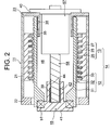
FIG. 2 is a sectional view of a drive apparatus
according to the second embodiment of the present invention.
In this case, in order to rotate the member-to-be-driven
15, an electric motor 57, such as a servomotor, which
serves as a rotary, second drive section, is attached to the
rear end face (right end face in the drawing) of the rear
plate 23 via the flange 40, which serves as a mounting
portion, and projects frontward (leftward in the drawing).
The motor 57 is of an inner rotor type and includes an
unillustrated stator and an unillustrated rotor, which is
rotatably disposed radially inward of the stator. The motor
57 is driven through supply of predetermined current; for
example, U-phase, V-phase, and W-phase currents, to the
stator, whereby the member-to-be-driven 15 can be rotated,
and the movable member can be rotated.
To achieve the above operation, an output shaft 58 of
the motor 57 is disposed at the center within the space 46
and extends frontward. The splines 39 are formed on the
outer circumferential surface of the front end (left end in
the drawing) of the output shaft 58 and serve as a driving
transmission element having the same length as the stroke of
the member-to-be-driven 15.
In this case, at least a portion of the motor 57; in
the present embodiment, not only the stator, the rotor, the
output shaft 58, and the like of the motor 57 but also the
rotation transmission section composed of the splines 39 and
44, is accommodated in the space 46. Thus, the cylindrical
linear motor 14 serving as the first drive section, the
stator, the rotor, the output shaft 58, and the like of the
motor 57, and the rotation transmission section can be
disposed in an overlapping condition along the axial
direction. Accordingly, the axial dimension of the drive
apparatus can further be reduced, and thus the size of the
drive apparatus can further be reduced, with a resultant
further reduction in the cost of the drive apparatus.
In the present embodiment, the movable element 12 and
the stationary element 13 are cylindrical, and the movable
element 12 and the stationary element 13 constitute the
cylindrical linear motor 14. However, the cross sections of
the movable element 12 and the stationary element 13 may
assume another shape; for example, a polygonal shape, whereby
the movable element 12 and the stationary element 13 can
constitute a linear motor having a tubular shape; for example,
a polygonally tubular shape. The core 26 and the coils 27
constitute a first drive element, and the permanent magnet 32
constitutes a second drive element.
Next, a third embodiment of the present invention will
be described. Like structural elements of the first and
third embodiments are denoted by like reference numerals, and
repeated description thereof is omitted. For the effect that
the third embodiment yields through employment of structural
elements similar to those of the first embodiment, its
description is omitted, and the description of the effect of
the first embodiment is incorporated herein by reference.
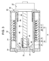
FIG. 3 is a sectional view of a drive apparatus
according to the third embodiment of the present invention.
In this case, the movable element 12 and the member-to-be-driven
15 are fixed to each other and are disposed in a
rotatable relationship to the housing 11 and in a manner
capable of advancing and retreating (moving in the left-right
direction in the drawing) in relation to the housing 11. In
order to allow such movements, a support member 55, such as a
linear ball bearing, is disposed on the outer circumferential
surface of the front end (left end in the drawing) of the
support portion 34 so as to support the movable member 12
such that the movable member 12 is movable in the axial
direction and in the circumferential direction. Also, an
unillustrated support member, such as a linear ball bearing,
is disposed on the inner circumferential surface of the front
plate 22 so as to support the movable element 12 such that
the movable member 12 is movable in the axial direction and
in the circumferential direction. No guide rails are
disposed on the housing 11. The core 26 and the coils 27
constitute a first drive element, and the permanent magnet 32
constitutes a second drive element.
In this case, the drive-processing means can perform a
driving process for driving the tubular linear motor 14,
which serves as the first drive section, while stopping the
drive of the motor 37, which serves as the second drive
section, so as to cause the member-to-be-driven 15 to advance
and retreat without rotating; driving the motor 37, while
stopping the drive of the linear motor 14, so as to rotate
the member-to-be-driven 15 without causing the member-to-be-driven
15 to advance and retreat; and driving the linear
motor 14 and the motor 37 so as to cause the member-to-be-driven
15 to advance and retreat while rotating.
When the member-to-be-driven 15 is caused to advance
and retreat, the motor 37 can be placed in a driven state so
as to prevent rotation of the member-to-be-driven 15. Also,
when the member-to-be-driven 15 is caused to rotate, the
linear motor 14 can be placed in a driven state so as to
prevent the member-to-be-driven 15 from advancing and
retreating. Alternatively, each of the motor 37 and the
linear motor 14 can be provided with a brake so as to be
placed in a braked state in place of being placed in a driven
state.
Next, a fourth embodiment of the present invention will
be described. Like structural elements of the second and
fourth embodiments are denoted by like reference numerals,
and repeated description thereof is omitted. For the effect
that the fourth embodiment yields through employment of
structural elements similar to those of the second embodiment,
its description is omitted, and the description of the effect
of the second embodiment is incorporated herein by reference.
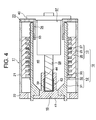
FIG. 4 is a sectional view of a drive apparatus
according to the fourth embodiment of the present invention.
In this case, in order to rotate the member-to-be-driven
15, an electric motor 57, such as a servomotor, which
serves as the rotary, second drive section, is attached to
the rear end face (right end face in the drawing) of the rear
plate 23 via the flange 40, which serves as a mounting
portion, and projects frontward (leftward in the drawing).
The motor 57 is of an inner rotor type and includes an
unillustrated stator and an unillustrated rotor, which is
rotatably disposed radially inward of the stator. The motor
57 can be driven through supply of predetermined current; for
example, U-phase, V-phase, and W-phase currents, to the
stator, whereby the member-to-be-driven 15 can be rotated,
and the movable member can be rotated.
To achieve the above operation, the output shaft 58 of
the motor 57 is disposed at the center within the space 46
and extends frontward. The splines 39 are formed on the
outer circumferential surface of the front end (left end in
the drawing) of the output shaft 58 and serve as the driving
transmission element having the same length as the stroke of
the member-to-be-driven 15.
The movable element 12 and the member-to-be-driven 15
are fixed to each other and are disposed in a rotatable
relationship to the housing 11 and in a manner capable of
advancing and retreating (moving in the left-right direction
in the drawing) in relation to the housing 11. Thus, the
support member 55, such as a linear ball bearing, is disposed
on the outer circumferential surface of the front end of the
support portion 34 in order to support the movable member 12
such that the movable member 12 is movable in the axial
direction and in the circumferential direction. Also, an
unillustrated support member, such as a linear ball bearing,
is disposed on the inner circumferential surface of the front
plate 22 in order to support the movable element 12 such that
the movable member 12 is movable in the axial direction and
in the circumferential direction. No guide rails are
disposed on the housing 11. The core 26 and the coils 27
constitute a first drive element, and the permanent magnet 32
constitutes a second drive element.
In this case, at least a portion of the motor 57; in
the present embodiment, not only the stator, the rotor, the
output shaft 58, and the like of the motor 57 but also the
rotation transmission section composed of the splines 39 and
44, is accommodated in the space 46. Thus, the cylindrical
linear motor 14 serving as the first drive section, the
stator, the rotor, the output shaft 58, and the like of the
motor 57, and the rotation transmission section can be
disposed in an overlapping condition along the axial
direction. Accordingly, the axial dimension of the drive
apparatus can further be reduced, and thus the size of the
drive apparatus can further be reduced, with a resultant
further reduction in the cost of the drive apparatus.
The drive-processing means can perform a driving
process for driving the linear motor 14, while stopping the
drive of the motor 57, so as to cause the member-to-be-driven
15 to advance and retreat without rotating; driving the motor
57, while stopping the drive of the linear motor 14, so as to
rotate the member-to-be-driven 15 without causing the member-to-be-driven
15 to advance and retreat; and driving the
linear motor 14 and the motor 57 so as to cause the member-to-be-driven
15 to advance and retreat while rotating.
When the member-to-be-driven 15 is caused to advance
and retreat, the motor 57 can be placed in a driven state so
as to prevent rotation of the member-to-be-driven 15. Also,
when the member-to-be-driven 15 is caused to rotate, the
linear motor 14 can be placed in a driven state so as to
prevent the member-to-be-driven 15 from advancing and
retreating. Alternatively, each of the motor 57 and the
linear motor 14 can be provided with a brake so as to be
placed in a braked state in place of being placed in a driven
state.
Next, a fifth embodiment of the present invention will
be described. Like structural elements of the first and
fifth embodiments are denoted by like reference numerals, and
repeated description thereof is omitted. For the effect that
the fifth embodiment yields through employment of structural
elements similar to those of the first embodiment, its
description is omitted, and the description of the effect of
the first embodiment is incorporated herein by reference.
FIG. 5 is a sectional view of a drive apparatus
according to the fifth embodiment of the present invention.
In the drawing, reference numeral 12 denotes a
cylindrical, movable element disposed within the housing 11
rotatably and in a manner capable of axially advancing and
retreating (moving in the left-right direction in the
drawing); reference numeral 13 denotes a cylindrical
stationary element attached to the inner circumferential
surface of the housing 11; and reference numeral 65 denotes a
member-to-be-driven, which is fixed to the movable element 12
and disposed such that the member-to-be-driven, together with
the movable element 12, is rotatable and can advance and
retreat in relation to the housing 11. The movable element
12 includes a cylindrical core 51, which is disposed radially
inward of the stationary element 13, and a permanent magnet
32, which is disposed on the outer circumferential surface of
the core 51 and over a predetermined axial range;
specifically, a distance of the axial length of the core 26
plus the stroke of the member-to-be-driven 65. The core 26
and the coils 27 constitute a first drive element, and the
permanent magnet 32 constitutes a second drive element.
In order to support the movable member 12 such that the
movable member 12 is rotatable and can advance and retreat,
the support member 55, such as a linear ball bearing, is
disposed on the outer circumferential surface of the front
end (left end in the drawing) of the support portion 34 so as
to support the movable member 12 such that the movable member
12 is movable in the axial direction and in the
circumferential direction. Also, an unillustrated support
member, such as a linear ball bearing, is disposed on the
inner circumferential surface of the front plate 22 so as to
support the movable element 12 such that the movable member
12 is movable in the axial direction and in the
circumferential direction. No guide rails are disposed on
the housing 11.
In order to rotate the member-to-be-driven 65, an
electric motor 67, such as a servomotor, which serves as a
rotary, second drive section, is attached to the rear end
face (right end face in the drawing) of the rear plate 23 via
a flange 60, which serves as a mounting portion, and projects
frontward (leftward in the drawing). The motor 67 is of an
outer rotor type and includes a support shaft 61, which
projects frontward from the flange 60 and is disposed at the
center within the space 46; a tubular, hollow output shaft 68,
which surrounds the support shaft 61 and is disposed in a
rotatable relationship to the support shaft 61; a stator 62,
which is attached to the outer circumferential surface of the
support shaft 61; and a rotor 63, which is disposed rotatably
and radially outward of the stator 62. Reference numerals b2
and b3 denote bearings.
The stator 62 includes a core 59 attached to the
support shaft 61, and coils 66 wound on the core 59. The
rotor 63 includes a core that serves as the output shaft 68,
and a permanent magnet 64 attached to the core. The motor 67
can be driven through supply of predetermined current; for
example, U-phase, V-phase, and W-phase currents, to the coils
66, whereby the member-to-be-driven 65 can be rotated, and
an unillustrated movable member attached to the member-to-be-driven
65 can be rotated.
To achieve the above operation, the output shaft 68 is
disposed within the space 46 and extends frontward, and
splines 69 are formed on the outer circumferential surface of
the front end of the output shaft 68 and serve as a driving
transmission element. Splines 54 are formed on the inner
circumferential surface of a front end portion (left end
portion in the drawing) of the core 51 along a length equal
to or longer than the stroke of the member-to-be-driven 65
and spline-engaged with the splines 69 so as to serve as a
driven transmission element. The splines 69 and 54
constitute a rotation transmission section. The rotation
transmission section transmits, to the member-to-be-driven 65,
rotation generated through drive of the motor 67 and output
to the output shaft 68, and allows axial movement of the
member-to-be-driven 65 in relation to the output shaft 68.
In this case, at least a portion of the motor 67; in
the present embodiment, not only the support shaft 61, the
stator 62, the rotor 63, the output shaft 68, and the like of
the motor 67 but also the rotation transmission section, is
accommodated in the space 46. Thus, the cylindrical linear
motor 14 serving as the first drive section, the support
shaft 61, the stator 62, the rotor 63, the output shaft 68,
and the like of the motor 67, and the rotation transmission
section can be disposed in an overlapping condition along the
axial direction. Accordingly, the axial dimension of the
drive apparatus can further be reduced, and thus the size of
the drive apparatus can further be reduced, with a resultant
further reduction in the cost of the drive apparatus.
The drive-processing means can perform a driving
process for driving the linear motor 14, while stopping the
drive of the motor 67, so as to cause the member-to-be-driven
65 to advance and retreat without rotating; driving the motor
67, while stopping the drive of the linear motor 14, so as to
rotate the member-to-be-driven 65 without causing the member-to-be-driven
65 to advance and retreat; and driving the
linear motor 14 and the motor 67 so as to cause the member-to-be-driven
65 to advance and retreat while rotating.
When the member-to-be-driven 65 is caused to advance
and retreat, the motor 67 can be placed in a driven state so
as to prevent rotation of the member-to-be-driven 65. Also,
when the member-to-be-driven 65 is caused to rotate, the
linear motor 14 can be placed in a driven state so as to
prevent the member-to-be-driven 65 from advancing and
retreating. Alternatively, each of the motor 67 and the
linear motor 14 can be provided with a brake so as to be
placed in a braked state in place of being placed in a driven
state.
In the present embodiment, the movable element 12 and
the stationary element 13 are cylindrical, and the movable
element 12 and the stationary element 13 constitute the
cylindrical linear motor 14. However, the cross sections of
the movable element 12 and the stationary element 13 may
assume another shape; for example, a polygonal shape, whereby
the movable element 12 and the stationary element 13 can
constitute a linear motor having a tubular shape; for example,
a polygonally tubular shape.
Next, a sixth embodiment of the present invention will
be described. Like structural elements of the fifth and
sixth embodiments are denoted by like reference numerals, and
repeated description thereof is omitted. For the effect that
the sixth embodiment yields through employment of structural
elements similar to those of the fifth embodiment, its
description is omitted, and the description of the effect of
the fifth embodiment is incorporated herein by reference.
FIG. 6 is a sectional view of a drive apparatus
according to the sixth embodiment of the present invention.
In the drawing, reference numeral 12 denotes a
cylindrical, movable element disposed within the housing 11
rotatably and in a manner capable of axially advancing and
retreating (moving in the left-right direction in the
drawing); reference numeral 13 denotes a cylindrical
stationary element attached to the inner circumferential
surface of the housing 11; and reference numeral 65 denotes a
member-to-be-driven, which is fixed to the movable element 12
and disposed such that the member-to-be-driven, together with
the movable element 12, is rotatable and can advance and
retreat in relation to the housing 11. The movable element
12 includes a cylindrical core 71, which is disposed radially
inward of the stationary element 13, and a permanent magnet
32, which is disposed on the outer circumferential surface of
the core 71 and over a predetermined axial range;
specifically, a distance of the axial length of the core 26
plus the stroke of the member-to-be-driven 65. The core 26
and the coils 27 constitute a first drive element, and the
permanent magnet 32 constitutes a second drive element.
In order to support the movable member 12 such that the
movable member 12 is rotatable and can advance and retreat,
the support member 55, such as a linear ball bearing, is
disposed on the outer circumferential surface of the front
end (left end in the drawing) of the support portion 34 so as
to support the movable member 12 such that the movable member
12 is movable in the axial direction and in the
circumferential direction. Also, an unillustrated support
member, such as a linear ball bearing, is disposed on the
inner circumferential surface of the front plate 22 so as to
support the movable element 12 such that the movable member
12 is movable in the axial direction and in the
circumferential direction. No guide rails are disposed on
the housing 11.
In order to rotate the member-to-be-driven 65, an
electric motor 77, such as a servomotor, which serves as a
rotary, second drive section, is attached to the rear end
face (right end face in the drawing) of the rear plate 23 via
the flange 60, which serves as a mounting portion, and
projects frontward (leftward in the drawing). The motor 77
is of an outer rotor type and includes the support shaft 61,
which projects frontward from the flange 60 and is disposed
at the center within the space 46; a tubular, hollow output
shaft, which serves as the core 71, surrounds the support
shaft 61, and is disposed in a rotatable relationship to the
support shaft 61; a stator 72, which is attached to the outer
circumferential surface of the support shaft 61; and a rotor
73, which is disposed rotatably and radially outward of the
stator 72.
The stator 72 includes the core 59 attached to the
support shaft 61, and the coils 66 wound on the core 59. The
rotor 73 includes the core 71 that serves as the output shaft,
and the permanent magnet 64 attached to the core 71. The
motor 77 can be driven through supply of predetermined
current; for example, U-phase, V-phase, and W-phase currents,
to the coils 66, whereby the member-to-be-driven 65 can be
rotated, and thus, the aforementioned movable member can be
rotated. The stator 72 is disposed over a distance of the
axial length of the permanent magnet 64 plus the stroke of
the member-to-be-driven 65.
In this case, at least a portion of the motor 77; in
the present embodiment, the support shaft 61, the stator 72,
the rotor 73, and the like of the motor 77, are accommodated
in the space 46. Thus, the cylindrical linear motor 14
serving as the first drive section, and the support shaft 61,
the stator 72, the rotor 73, and the like of the motor 77 can
be disposed in an overlapping condition along the axial
direction. Accordingly, the axial dimension of the drive
apparatus can further be reduced, and thus the size of the
drive apparatus can further be reduced, with a resultant
further reduction in the cost of the drive apparatus.
The drive-processing means can perform a driving
process for driving the linear motor 14, while stopping the
drive of the motor 77, so as to cause the member-to-be-driven
65 to advance and retreat without rotating; driving the motor
77, while stopping the drive of the linear motor 14, so as to
rotate the member-to-be-driven 65 without causing the member-to-be-driven
65 to advance and retreat; and driving the
linear motor 14 and the motor 77 so as to cause the member-to-be-driven
65 to advance and retreat while rotating.
When the member-to-be-driven 65 is caused to advance
and retreat, the motor 77 can be placed in a driven state so
as to prevent rotation of the member-to-be-driven 65. Also,
when the member-to-be-driven 65 is caused to rotate, the
linear motor 14 can be placed in a driven state so as to
prevent the member-to-be-driven 65 from advancing and
retreating. Alternatively, each of the motor 77 and the
linear motor 14 can be provided with a brake so as to be
placed in a braked state in place of being placed in a driven
state.
In this case, since the core 71 serves as the output
shaft of the motor 77, not only the size but also the weight
of the drive apparatus can be reduced.
In the present embodiment, the movable element 12 and
the stationary element 13 are cylindrical, and the movable
element 12 and the stationary element 13 constitute the
cylindrical linear motor 14. However, the cross sections of
the movable element 12 and the stationary element 13 may
assume another shape; for example, a polygonal shape, whereby
the movable element 12 and the stationary element 13 can
constitute a linear motor having a tubular shape; for example,
a polygonally tubular shape.
Next, a seventh embodiment of the present invention
will be described.
FIG. 7 is a sectional view of a drive apparatus
according to the seventh embodiment of the present invention.
In the drawing, reference numeral 11 denotes a
cylindrical housing; reference numeral 82 denotes a
cylindrical, movable element disposed within the housing 11
in a manner capable of axially advancing and retreating
(moving in the left-right direction in the drawing);
reference numeral 13 denotes a cylindrical stationary element
attached to the inner circumferential surface of the housing
11; and reference numeral 85 denotes a member-to-be-driven,
which is attached to the front end (left end in the drawing)
of the movable element 82 and disposed in a manner capable of
advancing and retreating together with the movable element 82.
The movable element 82 and the stationary element 13
constitute a tubular linear motor 84, which serves as the
first drive section.
The housing 11 includes the cylindrically tubular
portion 21; the annular front plate 22 attached to the front
end of the tubular portion 21; and an annular rear plate 83
attached to the rear end (right end in the drawing) of the
tubular portion 21. The stationary element 13 is attached to
the tubular portion 21 over a predetermined, substantially
central range along the axial direction.
The movable element 82 includes a cylindrical core 81,
which is disposed radially inward of the stationary element
13, and a permanent magnet 32, which is disposed on the outer
circumferential surface of the core 31 and over a
predetermined axial range; specifically, a distance of the
axial length of the core 26 plus the stroke of the member-to-be-driven
85. The core 26 and the coils 27 constitute a
first drive element, and the permanent magnet 32 constitutes
a second drive element.
In order to support the movable element 82 in an
axially movable relationship to the housing 11, unillustrated
guide rails, which serve as guide members, are disposed in an
axially extending manner on the housing 11 at
circumferentially predetermined positions. The movable
element 82 is caused to move along the guide rails. Notably,
it is possible to dispose an unillustrated slide portion on
the inner circumferential surface of each of the front plate
22 and the rear plate 83 so as to support the movable member
82 such that the outer circumferential surface of the core 81
slides on the slide portions.
Thus, thrust force can be generated through drive of
the linear motor 84, whereby the member-to-be-driven 85 can
be advanced (moved leftward in the drawing) by the thrust
force.
In order to increase thrust force to be applied to the
member-to-be-driven 85, the linear motor 87, which serves as
a linear-motion-type second drive section, is attached to the
front end of the core 81 via a flange 80, which serves as a
mounting portion, and extends rearward (rightward in the
drawing) within a cylindrical space 86 at the center thereof.
As in the case of the linear motor 84, the linear motor
87 includes an unillustrated movable element connected to the
member-to-be-driven 85 and an unillustrated stationary
element. The drive-processing means performs a driving
process for the linear motor 87 independently of the linear
motor 84. Specifically, the linear motor 87 can be driven
through supply of predetermined current; for example, U-phase,
V-phase, and W-phase currents, to the coils of the stationary
element, whereby the movable element and the member-to-be-driven
85 can be advanced and retreated. Through drive of
the linear motor 84 in the regular direction, thrust force
can be applied to the member-to-be-driven 85.
A hydraulic cylinder, a pneumatic cylinder, or the like
that serves as the second drive section can be disposed
within the space 86 as is the linear motor 87. In the
drawing, reference numeral 25 denotes magnetic-pole teeth,
and reference numeral 33 denotes magnetic poles.
In this case, the linear motor 84 transmits force
through a magnetic field (air). Therefore, when supply of
phase currents is stopped with resultant disappearance of the
magnetic field, the movable element 82 can be freely moved.
Accordingly, not only does the linear motor 84 enable the
drive apparatus to exhibit high-speed performance, high
responsiveness, and high control accuracy, but also the
linear motor 87 can sufficiently increase thrust force. As a
result, the drive apparatus can be mounted in a high-load
mechanical apparatus.
In the present embodiment, either an action source or a
reaction source of the linear motor 87 is fixed to the
movable element 82.
In the present embodiment, the movable element 82 and
the stationary element 13 are cylindrical, and the movable
element 82 and the stationary element 13 constitute the
cylindrical linear motor 84. However, the cross sections of
the movable element 82 and the stationary element 13 may
assume another shape; for example, a polygonal shape, whereby
the movable element 82 and the stationary element 13 can
constitute a linear motor having a tubular shape; for example,
a polygonally tubular shape.
Next, an eighth embodiment of the present invention
will be described. Like structural elements of the first and
eighth embodiments are denoted by like reference numerals,
and repeated description thereof is omitted. For the effect
that the eighth embodiment yields through employment of
structural elements similar to those of the first embodiment,
its description is omitted, and the description of the effect
of the first embodiment is incorporated herein by reference.
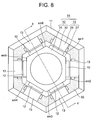
FIG. 8 is a cross-sectional view of a drive apparatus
according to the eighth embodiment of the present invention,
and FIG. 9 is a sectional view taken along line X―X of FIG.
8.
In the drawings, reference numeral 11 denotes a
polygonally tubular; in the present embodiment, a hexagonally
tubular housing; reference numeral 12 denotes a polygonally
tubular movable element; in the present embodiment, a
hexagonally tubular movable element disposed within the
housing 11 in a manner capable of axially advancing and
retreating (moving in the left-right direction in FIG. 9) and
formed of a material having high thermal conductivity, e.g.,
a metal; reference numeral 13 denotes each of stationary
elements attached to the inner circumferential surface of the
housing 11; and reference numeral 15 denotes a member-to-be-driven,
which is disposed in a rotatable relationship to the
movable element 12 via a bearing b1 and in a manner capable
of advancing and retreating together with the movable element
12. A movable member is fixed to the member-to-be-driven 15.
The movable element 12 and the stationary elements 13
constitute a polygonally tubular linear motor; in the present
embodiment, a hexagonally tubular linear motor 14, which
serves as a first drive section.
The housing 11 includes a hexagonally tubular portion
21; an annular front plate 22 attached to the front end (left
end in FIG. 9) of the tubular portion 21; and an annular rear
plate 23 attached to the rear end (right end in FIG. 9) of
the tubular portion 21. The stationary elements 13 are
attached to the tubular portion 21 over a predetermined,
substantially central range along the axial direction. Each
of the stationary elements 13 includes a core 26 having a
plurality of magnetic-pole teeth 25 formed in a radially
inward projecting condition and at predetermined pitch
spacings, and coils 27 wound on the corresponding magnetic-pole
teeth 25. The core 26 and the coils 27 constitute a
stator. The magnetic-pole teeth 25 are formed in parallel
with one another and along the perimetric direction of the
core 26.
The movable element 12 includes a hexagonally tubular
core 31, which is disposed radially inward of the stationary
elements 13, and permanent magnets 32, which are disposed on
the outer perimetric surface of the core 31 and over a
predetermined axial range; specifically, a distance of the
axial length of the core 26 plus the stroke of the member-to-be-driven
15. The permanent magnets 32 are magnetized such
that magnetic poles 33 serving as N pole and magnetic poles
33 serving as S pole are alternately formed at the same pitch
spacings as those of the magnetic-pole teeth 25. The
magnetic poles 33 are formed in parallel with one another and
along the perimetric direction of the core 31. The core 26
and the coils 27 constitute a first drive element, and the
permanent magnet 32 constitutes a second drive element. The
outer perimetric surface of the core 31 includes six
rectangular surfaces sm1 to sm6, and the permanent magnets 32
are attached to the respective surfaces sm1 to sm6.
As the linear motor 14 is driven, current is supplied
to the core 31 and causes the core 31 to generate heat. Thus,
a thermally conductive resin mold 90 is disposed along the
inner perimetric surface of the housing 11 in a manner
covering the stationary elements 13. The resin mold 90 is
formed of a resin having high thermal conductivity by means
of molding. Accordingly, heat generated in the core 31 is
transmitted to the housing 11 via the resin mold 90 and
released from the housing 11, so that the linear motor 14 can
be sufficiently cooled.
In the present embodiment, the movable element 12 and
the stationary element 13 are disposed in a hexagonal,
tubular shape, and the movable element 12 and the stationary
element 13 constitute the hexagonal, tubular linear motor 14.
However, the movable element 12 and the stationary element 13
may be disposed in another shape; for example, a cylindrical
shape, whereby the movable elements 12 and the stationary
elements 13 can constitute a tubular linear motor; for
example, a cylindrical linear motor.
When a material having high thermal conductivity and
high insulation quality; for example, alumina, is added to
the above-mentioned resin, the linear motor 14 can be cooled
more efficiently.
Next, application of the drive apparatus to an
injection apparatus mounted on a molding machine; for example,
an injection molding machine, will be described. In the
injection apparatus, the moving direction of a screw at an
injection step corresponds to the "front," and the moving
direction of the screw at a metering step corresponds to the
"rear."
FIG. 10 is a sectional view of an injection apparatus
according to a ninth embodiment of the present invention.
In the drawing, reference 11 denotes a cylindrical
housing, and reference 16 denotes a heating cylinder, which
serves as a cylinder member, attached to the front end (left
end in the drawing) of the housing 11. An unillustrated
hopper is disposed at a predetermined position of the rear
end (right end in the drawing) of the heating cylinder 16.
Reference numeral 17 denotes a screw, which serves as an
injection member, disposed within the heating cylinder 16
rotatably and in a manner capable of advancing and retreating
(moving in the left-right direction in the drawing). A
spiral flight 18 is formed on the screw 17, and a spiral
groove 19 is formed along the flight 18.
Reference numeral 12 denotes a cylindrical, movable
element disposed within the housing 11 in a manner capable of
axially advancing and retreating; reference numeral 13
denotes a cylindrical stationary element attached to the
inner circumferential surface of the housing 11; and
reference numeral 15 denotes a member-to-be-driven, which is
disposed in a rotatable relationship to the movable element
12 and in a manner capable of advancing and retreating
together with the movable element 12 and functions as a
torque/thrust-force transmission member for transmitting
torque and thrust force. The screw 17 is fixed to the
member-to-be-driven 15. The movable element 12 and the
stationary element 13 constitute a tubular injection linear
motor; in the present embodiment, a cylindrical injection
linear motor 14, which serves as a first drive section.
A load cell 28, which serves as a load-detecting
section, is disposed between the member-to-be-driven 15 and
the movable element 12. In order to support the member-to-be-driven
15 in a rotatable relationship to the movable
element 12, a bearing box 29, which serves as a bearing
support member, is attached to the front end of the movable
member 12 via the load cell 28. Bearings b11 and b12, which
serve as first and second bearing members, respectively, are
disposed within the bearing box 29 at axially front (left in
the drawing) and rear (right in the drawing) positions,
respectively. The bearing b11 is disposed between the outer
circumferential surface of the member-to-be-driven 15 and the
inner circumferential surface of the bearing box 29. The
bearing b12 is disposed between the rear end face (right end
face in the drawing) of a flange portion 36 of the member-to-be-driven
15 and the front end face (left end face in the
drawing) of a flange portion 52 of the bearing box 29,
thereby serving as a thrust bearing. The front end face of
the core 31 of the movable element 12 is fixed to a radially
outward portion of the rear end face of the load cell 28,
whereas the rear end face of the bearing box 29 is fixed to a
radially inward portion of the front end face of the load
cell 28.
The housing 11 includes a cylindrically tubular portion
21; a stepped annular front plate 122 attached to the front
end of the tubular portion 21; and an annular rear plate 23
attached to the rear end of the tubular portion 21. The
stationary element 13 is attached to the tubular portion 21
over a predetermined, substantially central range along the
axial direction. The stationary element 13 includes a core
26 having a plurality of magnetic-pole teeth 25 formed in a
radially inward projecting condition and at predetermined
pitch spacings, and coils 27 wound on the corresponding
magnetic-pole teeth 25. The magnetic-pole teeth 25 are
formed in parallel with one another and along the
circumferential direction of the core 26. The front plate
122 includes a large-diameter portion 141, which surrounds a
front end portion (left end portion in the drawing) of the
core 31 and the load cell 28, and a small-diameter portion 42,
which surrounds the bearing box 29 and the member-to-be-driven
15.
The movable element 12 includes a cylindrical core 31,
which is disposed radially inward of the stationary element
13, and a permanent magnet 32, which is disposed on the outer
circumferential surface of the core 31 and over a
predetermined axial range; specifically, a distance of the
axial length of the core 26 plus the stroke of the screw 17.
The permanent magnet 32 is magnetized such that magnetic
poles 33 serving as N pole and magnetic poles 33 serving as S
pole are alternately formed at the same pitch spacings as
those of the magnetic-pole teeth 25. The magnetic poles 33
are formed in parallel with one another and along the
circumferential direction of the core 31. The core 26 and
the coils 27 constitute a first drive element, and the
permanent magnet 32 constitutes a second drive element.
In order to support the movable element 12 in an
axially movable relationship to the housing 11, unillustrated
guide rails, which serve as axial guide members, are disposed
in an axially extending manner on the housing 11 at
circumferentially predetermined positions. The movable
element 12 is caused to move along the guide rails. An
annular slide portion 45, which serves as a first guide
member, is formed on the inner circumferential surface of the
rear end of the front plate 122 and at a front portion (left
portion in the drawing) of the movable element 12. A tubular
support portion 34 is formed on the rear plate 23 in a manner
projecting frontward from the inner circumferential edge of
the rear plate 23 by a length equal to the stroke of the
screw 17. An annular slide portion 35, which serves as a
second guide member, is formed on the outer circumferential
surface of the front end of the support portion 34 and at a
rear portion (right portion in the drawing). The front plate
122 supports the movable element 12 such that the outer
circumferential surface of the core 31 slides on the slide
portion 45, and the support portion 34 supports the movable
element 12 such that the inner circumferential surface of the
core 31 slides on the slide portion 35. Also, in this manner,
the front plate 122 and the support portion 34 position the
movable element 12 in relation to the stationary element 13.
In this case, preferably, in order to enhance positioning
accuracy, the support portion 34 is formed integrally with
the rear plate 23. However, the support portion 34 may be
formed as a separate member. Notably, a bush or a self-lubricating
material, which does not require application of
lubricant, can be used to form the slide portions 35 and 45.
In this case, the slide portion 45 supports and guides
the movable element 12 from the outside at the output side of
the linear motor 14; in the present embodiment, at a front
portion of the movable element 12, and the slide portion 35
supports and guides the movable element 12 from the inside at
the non-output side of the linear motor 14; in the present
embodiment, at a rear portion of the movable element 12.
Thus, the length of the core 31 can be shortened accordingly.
Therefore, the axial dimension of the linear motor 14 can be
reduced.
Meanwhile, the linear motor 14 can be driven through
supply of predetermined current; for example, U-phase, V-phase,
and W-phase currents, to the coils 27, whereby the
movable element 12 can be axially advanced and retreated, and
thus the member-to-be-driven 15 can be advanced and retreated.
In order to drive the linear motor 14, an unillustrated
control section is disposed, and an unillustrated inverter is
connected to the coils 27. A drive-processing means of the
control section performs a drive process so as to generate a
predetermined drive signal, and supplies the drive signal to
the inverter. Upon reception of the drive signal, the
inverter generates currents of the above-mentioned phases and
supplies the currents to the coils 27. In this case, in
accordance with the drive signal, the inverter can change
patterns of generating the currents of the above-mentioned
phases so as to drive the linear motor 14 in the regular
direction for causing the movable element 12 to advance (move
leftward in the drawing), or to drive the linear motor 14 in
the reverse direction for causing the movable element 12 to
retreat (move rightward in the drawing). When the movable
element 12 is caused to advance, the load cell 28 can detect
an associated thrust force. Supply of the detected thrust
force to the control section enables feedback control.
As a result, a predetermined thrust force can be
generated through drive of the linear motor 14. The thrust
force is transmitted to the screw 17 via the member-to-be-driven
15, whereby the thrust force can be used as an
injection force for causing the screw 17 to perform injection.
A small clearance is formed between the movable element 12
and the stationary element 13. The present embodiment can
render the clearance very small, since the core 31 is
positioned in the radially outward direction by means of the
slide portion 45 and in the radially inward direction by
means of the slide portion 35. Therefore, the thrust force
can be increased accordingly.
Since the slide portion 35 is disposed radially inward
of the movable element 12, the linear motor 14 and the
support portion 34 can be disposed in an overlapping
condition along the axial direction. Thus, the size of the
injection apparatus can be reduced.
In order to rotate the member-to-be-driven 15, an
electric metering motor 37, such as a servomotor, which
serves as a second drive section, is attached to the rear end
face of the rear plate 23 via a flange 40, which serves as a
mounting portion, and projects rearward. The motor 37 is of
an inner rotor type and includes an unillustrated stator and
an unillustrated rotor, which is rotatably disposed radially
inward of the stator. The motor 37 can be driven through
supply of predetermined current; for example, U-phase, V-phase,
and W-phase currents, to the stator, whereby the
member-to-be-driven 15 can be rotated, and thus, the screw 17
can be rotated.
To achieve the above operation, a space 46 having a
predetermined shape; in the present embodiment, a cylindrical
shape, is formed radially inward of the movable element 12.
An output shaft 38 of the motor 37 is disposed at the center
within the space 46 and extends frontward. Splines 39 are
formed on the outer circumferential surface of a front end
portion of the output shaft 38 and serve as a driving
transmission element having the same length as the stroke of
the screw 17. The member-to-be-driven 15 includes a base
portion 50 having the flange portion 36 formed on the outer
circumferential surface thereof, and a tubular holder portion
43, which projects rearward from the base portion 50 over a
distance equal to the stroke of the screw 17. Splines 44 are
formed on the inner circumferential surface of the rear end
of the holder portion 43 and spline-engaged with the splines
39 so as to serve as a driven transmission element. The
splines 39 and 44 constitute a rotation transmission section.
The rotation transmission section transmits rotation and
torque generated through drive of the motor 37 and output to
the output shaft 38, to the member-to-be-driven 15 and then
to the screw 17. Also, the rotation transmission section
allows axial movement of the member-to-be-driven 15 and the
screw 17 in relation to the output shaft 38. In this case,
even when transmission of rotation to the movable element 12
via the bearings b11 and b12, the bearing box 29, and the
load cell 28 is attempted as the member-to-be-driven 15 is
rotated, the guide rails prevent rotation of the movable
element 12. In other words, the guide rails function as a
rotation stop.
Next, the operation of the thus-configured injection
apparatus will be described.
When the injection molding machine is at a metering
step, a metering-processing means of the drive-processing
means performs a metering process, thereby causing the motor
37 to rotate in the regular direction. This causes the
output shaft 38 to rotate in the regular direction. The
rotation of the output shaft 38 is transmitted to the member-to-be-driven
15 via the splines 39 and 44, so that the screw
17 is rotated. The rotation of the screw 17 causes a resin,
which serves as a molding material, supplied from the hopper
moves frontward in the groove 19 while being melted. The
resin is stored ahead of the screw 17 by a predetermined
amount. The resin stored ahead of the screw 17 presses the
screw 17 and causes the screw 17 to move rearward.
Subsequently, when the movable element 12 is brought to its
retreat limit position, the front end of the core 26 and that
of the permanent magnet 32 substantially coincide with each
other, and the splines 44 are brought to the rear-end
position of the splines 39.
At an injection step, an injection-processing means of
the drive-processing means performs an injection process,
thereby driving the linear motor 14 so as to generate a
predetermined thrust force. The thrust force causes the
movable element 12 to advance. Advancement of the movable
element 12 causes the member-to-be-driven 15 to advance,
thereby causing the screw 17 to advance. The resin stored
ahead of the screw 17 is ejected from injection nozzle 151
disposed at the front end of the heating cylinder 16.
Thus, by virtue of using the linear motor 14 as the
first drive section, the drive apparatus can exhibit high-speed
performance, high responsiveness, and high control
accuracy. The movable element 12 and the stationary element
13 constitute the cylindrical linear motor 14. At least a
portion of the motor 37; in the present embodiment, not only
the output shaft 38 but also the rotation transmission
section, is accommodated in the space 46. Thus, the linear
motor 14, the output shaft 38, and the rotation transmission
section can be disposed in an overlapping condition along the
axial direction. Accordingly, the axial dimension of the
injection apparatus can be reduced, and thus the size of the
injection apparatus can be reduced, with a resultant
reduction in the cost of the injection apparatus.
Since the movable element 12 and the stationary element
13 constitute the tubular linear motor 14, the area of the
permanent magnet 32 can be sufficiently increased by merely a
slight increase in a radial dimension. Accordingly, since
the capacity of the linear motor 14 can be increased, the
linear motor 14 can generate a large thrust force and can
provide short-cycled continuous drive. As a result,
injection can be performed with a large injection force, and
molding can be performed in short molding cycles.
Since the motor 37 can be disposed on the axis of
rotation of the screw 17, the moment of inertia can be
reduced. Accordingly, the drive apparatus can be further
enhanced in terms of high-speed performance, high
responsiveness, and high control accuracy.
Since the stationary element 13 and the motor 37 are
attached to the housing 11, when the linear motor 14 is
driven, the movable element 12 moves, whereas the motor 37
remains stationary. Accordingly, the weight of a movable
portion of the injection apparatus is reduced, so that the
moment of inertia can be reduced. As a result, the drive
apparatus can be further enhanced in terms of high-speed
performance, high responsiveness, and high control accuracy.
Since there is no need to dispose a rotation
transmission system, such as a belt or a chain, between the
member-to-be-driven 15 and the motor 37; i.e., the member-to-be-driven
15 can be rotated by means of direct drive, noise
generated in association with transmission of rotation can be
greatly reduced. Since the diameter of the output shaft 38
can be reduced, the moment of inertia can be reduced. Thus,
energy that is consumed for driving the motor 37 is reduced,
so that the drive efficiency can be enhanced.
Further, even when the motor 37 assumes a long, thin
structure, at least a portion of the motor 37 can be
accommodated in the movable element 12, so that the axial
dimension of the injection apparatus can be reduced.
Since the rotational speed of the motor 37 can be
detected on the rotational shaft by use of an unillustrated
rotation detector, a method of attaching the rotation
detection can be simplified.
In the present embodiment, the movable element 12 and
the stationary element 13 are cylindrical, and the movable
element 12 and the stationary element 13 constitute the
cylindrical linear motor 14. However, the cross sections of
the movable element 12 and the stationary element 13 may
assume another shape; for example, a polygonal shape, whereby
the movable element 12 and the stationary element 13 can
constitute a linear motor having a tubular shape; for example,
a polygonally tubular shape.
Next, a tenth embodiment of the present invention will
be described. Like structural elements of the ninth and
tenth embodiments are denoted by like reference numerals, and
repeated description thereof is omitted. For the effect that
the tenth embodiment yields through employment of structural
elements similar to those of the ninth embodiment, its
description is omitted, and the description of the effect of
the ninth embodiment is incorporated herein by reference.
FIG. 11 is a sectional view of an injection apparatus
according to the tenth embodiment of the present invention.
In this case, in order to rotate the member-to-be-driven
15, an electric metering motor 57, such as a
servomotor, which serves as a second drive section, is
attached to the rear end face (right end face in the drawing)
of the rear plate 23 via the flange 40, which serves as a
mounting portion, and projects frontward (leftward in the
drawing). The motor 57 is of an inner rotor type and
includes a case 161; a stator 162 attached to the case 161; a
rotor 163, which is disposed radially inward of the stator
162 and rotatably in relation to the case 161 by means of
bearings b13 and b4; and an output shaft 58 formed integrally
with the rotor 163. The motor 57 can be driven through
supply of predetermined current; for example, U-phase, V-phase,
and W-phase currents, to a coil 164 in the stator 162,
whereby the member-to-be-driven 15 can be rotated, and thus,
the screw 17, which serves as an injection member, can be
rotated.
To achieve the above operation, the output shaft 58 is
disposed at the center within the space 46 and extends
frontward. The splines 39 are formed on the outer
circumferential surface of a front end portion (left end
portion in the drawing) of the output shaft 58 and serve as a
driving transmission element having the same length as the
stroke of the member-to-be-driven 15.
In this case, at least a portion of the motor 57; in
the present embodiment, not only the stator 162, the rotor
163, the output shaft 58, and the like of the motor 57 but
also the rotation transmission section composed of the
splines 39 and 44, is accommodated in the space 46. Thus,
the cylindrical, injection-effecting linear motor 14, which
serves as a first drive section, the stator 162, the rotor
163, the output shaft 58, and the like of the motor 57, and
the rotation transmission section can be disposed in an
overlapping condition along the axial direction. Accordingly,
the axial dimension of the injection apparatus can be reduced,
and thus the size of the injection apparatus can be reduced,
with a resultant reduction in the cost of the injection
apparatus.
In the present embodiment, the movable element 12 and
the stationary element 13 are cylindrical, and the movable
element 12 and the stationary element 13 constitute the
cylindrical linear motor 14. However, the cross sections of
the movable element 12 and the stationary element 13 may
assume another shape; for example, a polygonal shape, whereby
the movable element 12 and the stationary element 13 can
constitute a linear motor having a tubular shape; for example,
a polygonally tubular shape. The core 26 and the coils 27
constitute a first drive element, and the permanent magnet 32
constitutes a second drive element.
The ninth and tenth embodiments use the motors 37 and
57 of an inner rotor type. However, an electric metering
motor of an outer rotor type can be used.
Next will be described an eleventh embodiment of the
present invention that uses a metering motor of an outer
rotor type. Like structural elements of the ninth and
eleventh embodiments are denoted by like reference numerals,
and repeated description thereof is omitted. For the effect
that the eleventh embodiment yields through employment of
structural elements similar to those of the ninth embodiment,
its description is omitted, and the description of the effect
of the ninth embodiment is incorporated herein by reference.
FIG. 12 is a sectional view of an injection apparatus
according to the eleventh embodiment of the present invention.
In this case, in order to rotate the member-to-be-driven
15, an electric metering motor 177, such as a
servomotor, which serves as a second drive section, is
attached to the rear end face (right end face in the drawing)
of the rear plate 23 via the flange 70, which serves as a
mounting portion, and projects frontward (leftward in the
drawing). A tubular support portion 74 is formed on the rear
plate 23 in a manner projecting frontward from the inner
circumferential edge of the rear plate 23. A slide portion
75 is formed on the outer circumferential surface of the
front end of the support portion 74.
The motor 177 is of an outer rotor type and includes a
support shaft 76, which is attached to the flange 70 and
projects frontward within the space 46; a tubular rotor 78,
which surrounds the support shaft 76 and is disposed in a
rotatable relationship to the support shaft 76 by means of
bearings b5 and b6 and in a rotatable relationship to the
support portion 74 by means of bearings b7 and b8; a stator
79 attached, in opposition to the rotor 78, to the outer
circumferential surface of the support shaft 76; and an
output shaft 58 integrally formed at the front end (left end
in the drawing) of the rotor 78. The output shaft 58 and the
member-to-be-driven 15 are spline-engaged together by means
of the splines 39 and 44. Reference numeral 181 denotes
teeth formed on the outer circumferential surface of the rear
end (right end in the drawing) of the rotor 78 and serving as
an object to be detected. Reference numeral 182 denotes a
sensor, which is attached to the rear plate 23 in opposition
to the teeth 181 and serves as a rotation detector for
detecting the rotational speed of the rotor 78. The core 26
and the coils 27 constitute a first drive element, and the
permanent magnet 32 constitutes a second drive element.
In the present embodiment, the rotor 78 is disposed in
a rotatable relationship to the support shaft 76 and the
support portion 74. However, the rotor 78 may be disposed in
a rotatable relationship to either the support shaft 76 or
the support portion 74.
Use of the motor 177 of an outer rotor type can
increase a motor torque that is generated when the motor 177
is driven.
Next, application of the drive apparatus to a mold
clamping apparatus mounted on a molding machine; for example,
an injection molding machine, will be described. In the mold
clamping apparatus, the moving direction of a movable platen
at a mold closing step corresponds to the "front," and the
moving direction of the movable platen at a mold opening step
corresponds to the "rear."
FIG. 13 is a front view of a mold apparatus and a mold
clamping apparatus according to a twelfth embodiment of the
present invention; FIG. 14 is a plan view of the mold
apparatus and the mold clamping apparatus according to the
twelfth embodiment; FIG. 15 is a sectional view showing a
mold clamped condition of the mold apparatus according to the
twelfth embodiment; and FIG. 16 is a front view showing a
mold open condition of the mold apparatus according to the
twelfth embodiment.
In the drawings, reference numeral 251 denotes a mold
clamping apparatus. The mold clamping apparatus 251 includes
a stationary platen 252 attached to a frame Fr of a molding
machine, e.g., an injection molding machine, and serving as a
first stationary section; a base plate (toggle support) 253
spaced by a predetermined distance apart from the stationary
platen 252, attached to the frame Fr, and serving as a second
stationary section; four tie bars 254 (only two tie bars 254
appear in the drawings) extending between the stationary
platen 252 and the base plate 253 and serving as connection
members; a movable platen 256 disposed in a manner capable of
advancing and retreating (moving in the left-right direction
in the drawings) between the stationary platen 252 and the
base plate 253 along the tie bars 254 and serving as a
movable section; and a mold clamping mechanism 255 disposed
between the movable platen 256 and the base plate 253 and
causing the movable platen 256 to advance and retreat.
A stationary mold 261, which serves as a first mold, is
attached to the stationary platen 252 on its face in
opposition to the movable platen 256. A movable mold 262,
which serves as a second mold, is attached to the movable
platen 256 on its face in opposition to the stationary platen
252. The stationary mold 261 and the movable mold 262
constitute a mold apparatus 263.
The mold clamping mechanism 255 includes a housing 211
disposed in a manner capable of advancing and retreating
along the tie bars 254; a tubular clamping linear motor; in
the present embodiment, a cylindrical clamping linear motor
214, which serves as a first drive section; and a toggle
mechanism 265 disposed between the movable platen 256 and the
base plate 253, adapted to generate a mold clamping force by
means of amplification of thrust force generated by the
linear motor 214, and serving as an amplifying mechanism
section.
The linear motor 214 includes a cylindrical stationary
element 212, whose rear end (left end in the drawings) is
slidably supported by the base plate 253 via a tubular member
257 and which extends frontward (rightward in the drawings)
through the housing 211; and a cylindrical movable element
213, which is attached to the inner circumferential surface
of the housing 211 and extends in a manner surrounding the
stationary element 212.
The housing 211 includes a cylindrically tubular
portion 221; a rectangular front plate 222 attached to the
front end (right end in the drawings) of the tubular portion
221; and a rectangular rear plate 223 attached to the rear
end of the tubular portion 221. The movable element 213 is
attached to the inner circumferential surface of the tubular
portion 221. Holes h1 and h2 are formed in the front and
rear plates 222 and 223, respectively, so as to allow the
stationary element 212 to extend therethrough.
The movable element 213 includes a core 226 having a
plurality of magnetic-pole teeth 225 formed in a radially
inward projecting condition and at predetermined pitch
spacings, and coils 227 wound on the corresponding magnetic-pole
teeth 225. The magnetic-pole teeth 225 are formed in
parallel with one another and along the circumferential
direction of the core 226.
Since one end of the core 226 is attached to the
cylindrical stationary element 212, and the other end of the
core 226 is supported by the tubular member 257 disposed in
the base plate 253, the movable platen 256 can stably advance
and retreat, and rectilinearity of the movable platen 256 can
be enhanced. In the present embodiment, the core 226 is
formed of a single tubular member. However, the core 226 may
be formed of a plurality of members.
The stationary element 212 includes a cylindrical core
231, which is disposed radially inward of the movable element
213 and fixed to the movable platen 256, and a permanent
magnet 232, which is disposed on the outer circumferential
surface of the core 231 and over a predetermined axial range;
specifically, a distance of the axial length of the core 226
plus the stroke of a crosshead 271, which serves as an
advancing-retreating member. The permanent magnet 232 is
magnetized such that magnetic poles 233 serving as N pole and
magnetic poles 233 serving as S pole are alternately formed
at the same pitch spacings as those of the magnetic-pole
teeth 225. The magnetic poles 233 are formed in parallel
with one another and along the circumferential direction of
the core 231. The core 226 and the coils 227 constitute a
first drive element, and the permanent magnet 232 constitutes
a second drive element.
The toggle mechanism 265 includes toggle levers 267,
which are pivotably connected, via corresponding pins p1, to
a bracket Br1 attached to the front end face (right end face
in the drawings) of the base support 253; toggle arms 268,
which are pivotably connected, via corresponding pins p2, to
a bracket Br2 attached to the rear end face (left end face in
the drawings) of the movable platen 256, and pivotably
connected to the corresponding toggle levers 267 via
corresponding pins p3; and toggle levers 272, which are
pivotably connected to the corresponding toggle arms 268 via
corresponding pins p4 and to the crosshead 271 via
corresponding pins p5. The crosshead 271 is attached to a
predetermined position of the housing 211; in the present
embodiment, the front plate 222, and is disposed in a manner
capable of advancing and retreating together with the movable
element 213.
Meanwhile, the linear motor 214 is driven through
supply of predetermined current; for example, U-phase, V-phase,
and W-phase currents, to the coils 227, whereby the
movable element 213 can be advanced and retreated, and thus,
the crosshead 271 can be advanced and retreated, the toggle
mechanism 265 can be activated, and the movable platen 256
can be caused to advance and retreat. In this case, through
drive of the linear motor 214, a predetermined thrust force
is generated in the movable element 213. As the clearance
between the stationary element 212 and the movable element
213 reduces, the thrust force increases.
In order to drive the linear motor 214, an
unillustrated control section is disposed, and an
unillustrated inverter is connected to the coils 227. In
this case, when a predetermined drive signal is generated and
supplied to the inverter, the inverter generates currents of
the above-mentioned phases and supplies the currents to the
coils 227. Accordingly, by means of controlling the drive
signal, the linear motor 214 can be driven in the regular
direction or in the reverse direction.
By means of driving the linear motor 214 so as to cause
the crosshead 271 to advance and retreat, the mold apparatus
263 can undergo mold closing, mold clamping, and mold opening.
The stationary element 212 has a cylindrical shape so
as to form a space 246 having a circular cross section within
the stationary element 212. An ejector apparatus 275 is
disposed within the space 246. The ejector apparatus 275
includes an ejection-effecting electric motor 276, which
serves as a second drive section; a ball screw 277 for
converting rotary motion generated through drive of the motor
276 to rectilinear motion, the ball screw 277 serving as a
motion direction conversion section; a plurality of ejector
rods 278 connected to the ball screw 277 and extending
frontward through the movable platen 256; and unillustrated
ejector pins disposed ahead of the corresponding ejector rods
278 and within the movable mold 262, in a manner capable of
advancing and retreating.
In this case, the linear motor 214 and at least a
portion of the motor 276; in the present embodiment, the
entire motor 276, the ball screw 277, rear portions (left
portions in the drawings) of the ejector rods 278, and the
like, are disposed in an overlapping condition. Accordingly,
the axial dimension of the mold clamping apparatus can be
reduced, and thus the size of the mold clamping apparatus can
be reduced, with a resultant reduction in the cost of the
mold clamping apparatus.
Next, the operation of the thus-configured mold
clamping apparatus 251 will be described.
First, at a mold closing step, a mold-closing-processing
means of the control section performs a mold
closing process and generates an associated, predetermined
drive signal so as to drive the linear motor 214 in the
regular direction. The activation causes the movable element
213 to retreat (move leftward in the drawings) toward the
base plate 253. The retreat causes the crosshead 271 to
retreat, thereby operating the toggle mechanism 265 so as to
cause the movable platen 256 to advance (move rightward in
the drawings). The advancement causes the mold apparatus 263
to undergo mold closing, thereby causing the movable mold 262
to abut the stationary mold 261. As a result, an
unillustrated cavity is formed between the stationary mold
261 and the movable mold 262. Through drive of the linear
motor 214, thrust force can be generated in the movable
element 213. The thrust force is transmitted to the toggle
mechanism 265 via the crosshead 271 and amplified by the
toggle mechanism 265.
Subsequently, at a mold clamping step, a mold-clamping-processing
means of the control section performs a mold
clamping process and generates an associated, predetermined
drive signal so as to further operate the linear motor 214 in
the regular direction. The further operation causes the
toggle mechanism 265 to amplify the thrust force generated in
the movable element 213, under toggle magnification, thereby
generating a predetermined mold clamping force. Accordingly,
mold clamping is performed such that the movable mold 262 is
further pressed against the stationary mold 261 by the mold
clamping force. At this time, resin as a molding material is
ejected from an injection nozzle 151 of the injection
apparatus (FIG. 12) and charged into the cavity.
At a mold opening step, a mold-opening-processing means
of the control section performs a mold opening process so as
to drive the linear motor 214 in the reverse direction. As
shown in FIG. 16, the activation causes the movable element
213 to advance. The advancement causes the crosshead 271 to
advance, thereby causing the movable platen 256 to retreat.
Thus, the movable mold 262 can be separated from the
stationary mold 261. In this manner, the mold apparatus 263
undergoes mold opening.
Thus, by virtue of using the linear motor 214 as a
drive section of the mold clamping apparatus 251, the drive
apparatus can exhibit high-speed performance, high
responsiveness, and high control accuracy. Since the
stationary element 212, the movable element 213, and the like
constitute the tubular linear motor 214, the area of the
permanent magnet 232 can be sufficiently increased by merely
a slight increase in a radial dimension. Accordingly, since
the capacity of the linear motor 214 can be increased, the
linear motor 214 can generate a large thrust force and
enables the mold clamping apparatus 251 to continuously
operate in short molding cycles. As a result, the size of
the mold clamping apparatus 251 can be reduced accordingly,
and the cost of the mold clamping apparatus 251 can be
reduced accordingly.
Since the linear motor 214 and at least a portion of
the ejector apparatus 275; in the present embodiment, the
entire motor 276, the ball screw 277, rear portions of the
ejector rods 278, and the like, are disposed in an
overlapping condition, the axial dimension of the mold
clamping apparatus 251 can be reduced, and thus the size of
the mold clamping apparatus 251 can further be reduced.
In the present embodiment, the stationary element 212
and the movable element 213 have a cylindrical shape, and the
stationary element 212, the movable element 213, and the like
constitute the cylindrical linear motor 214. However, the
cross sections of the stationary element 212 and the movable
element 213 may assume another shape; for example, a
polygonal shape, whereby the stationary element 212 and the
movable element 213 can constitute a linear motor having a
tubular shape; for example, a polygonally tubular shape.
Next, a thirteenth embodiment of the present invention
will be described. Like structural elements of the twelfth
and thirteenth embodiments are denoted by like reference
numerals, and repeated description thereof is omitted. For
the effect that the thirteenth embodiment yields through
employment of structural elements similar to those of the
twelfth embodiment, its description is omitted, and the
description of the effect of the twelfth embodiment is
incorporated herein by reference.
FIG. 17 is a sectional view showing a mold apparatus in
a mold clamped condition according to a thirteenth embodiment
of the present invention.
In this case, an ejector apparatus 285 is disposed
within the space 246. The ejector apparatus 285 includes an
ejection-effecting linear motor 286, which serves as a second
drive section; a plurality of ejector rods 278 which extend
frontward (rightward in the drawing) through the movable
platen 256 and which are advanced and retreated (moved in the
left-right direction in the drawing) through drive of the
linear motor 286; and unillustrated ejector pins disposed
ahead of the corresponding ejector rods 278 and within the
movable mold 262, which serves as a second mold, in a manner
capable of advancing and retreating.
The linear motor 286 includes a cylindrical housing 287
attached to the inner circumferential surface of the core
231; a cylindrical, movable element 288 disposed within the
housing 287 in a manner capable of advancing and retreating
and composed of a core 91 and a permanent magnet 92; and an
unillustrated stationary element attached to the inner
circumferential surface of the housing 287 and surrounding
the movable element 288. The ejector rods 278 are connected
to the movable element 288.
In this case, the linear motor 214, which serves as a
first drive section, and at least a portion of the linear
motor 286; in the present embodiment, the entire linear motor
286, rear portions (left portions in the drawings) of the
ejector rods 278, and the like, are disposed in an
overlapping condition. Accordingly, the axial dimension of
the mold clamping apparatus 251 (FIG. 16) can be reduced, and
thus the size of the mold clamping apparatus 251 can be
reduced.
In the twelfth and thirteenth embodiments, the
stationary element 212 is fixed to the base plate 253, which
serves as a second stationary section; the movable element
213 is disposed in a manner capable of advancing and
retreating; and the crosshead 271, which serves as an
advancing-retreating member, is fixed to the movable element
213. However, the following structure may be acceptable: the
housing 211 is fixed to the tie bars 254, which serve as
connection members, so that the core 226 and the coils 227
constitute a stationary element; and the core 231 and the
permanent magnet 232 constitute a movable element. In this
case, the crosshead 271 is attached to the core 231 at a
predetermined position.
The core 226 and the coils 227 constitute a first drive
element, and the permanent magnet 232 constitutes a second
drive element.
Next, a fourteenth embodiment of the present invention
will be described. Like structural elements of the twelfth
and fourteenth embodiments are denoted by like reference
numerals, and repeated description thereof is omitted. For
the effect that the fourteenth embodiment yields through
employment of structural elements similar to those of the
twelfth embodiment, its description is omitted, and the
description of the effect of the twelfth embodiment is
incorporated herein by reference.
FIG. 18 is a front view of a mold apparatus and a mold
clamping apparatus according to the fourteenth embodiment of
the present invention, and FIG. 19 is a sectional view
showing a mold clamped condition of the mold apparatus
according to the fourteenth embodiment.
In this case, the stationary element 212 is fixed to
the base plate 253, which serves as a second stationary
section. Advancement (rightward movement in the drawings) of
the movable element 213 effects mold closing, and retreat
(leftward movement in the drawings) of the movable element
213 effects mold opening.
To achieve the above operation, the toggle mechanism
265, which serves as an amplifying mechanism section,
includes toggle levers 167, which are pivotably connected,
via corresponding pins p11, to a bracket Br11 formed on the
rear end face (left end face in the drawings) of the movable
platen 256, which serves as a movable section; toggle arms
168, which are pivotably connected, via corresponding pins
p12, to a bracket Br12 formed on the front end face (right
end face in the drawings) of the base plate 253, and
pivotably connected to the corresponding toggle levers 167
via corresponding pins p13; and toggle levers 172, which are
pivotably connected to the corresponding toggle arms 168 via
corresponding pins p14, and pivotably connected, via
corresponding pins p15, to the crosshead 271, which serves as
an advancing-retreating member.
The crosshead 271 is attached to a predetermined
position of the housing 211; in the present embodiment, the
rear plate 223, and is disposed in a manner capable of
advancing and retreating together with the movable element
213.
The stationary element 212 has a cylindrical shape so
as to form a space 246 having a circular cross section within
the stationary element 212. An ejector apparatus 275 is
disposed within the space 246. The ejector apparatus 275
includes an ejection-effecting electric motor 276, which
serves as a second drive section; a ball screw 277 for
converting rotary motion generated through drive of the motor
276 to rectilinear motion, the ball screw 277 serving as a
motion direction conversion section; a plurality of ejector
rods 278 connected to the ball screw 277 and extending
frontward (rightward in the drawings) through the movable
platen 256; and unillustrated ejector pins disposed ahead of
the corresponding ejector rods 278 and within the movable
mold 262, which serves as a second mold, in a manner capable
of advancing and retreating.
The core 226 and the coils 227 constitute a first drive
element, and the permanent magnet 232 constitutes a second
drive element.
The present invention is not limited to the above-described
embodiments. Numerous modifications and variations
of the present invention are possible in light of the spirit
of the present invention, and they are not excluded from the
scope of the present invention.
INDUSTRIAL APPLICABILITY
The present invention can be applied to a mechanical
apparatus having a linear motor.