EP1607204A2 - Manufacture of laminar mouldings - Google Patents
Manufacture of laminar mouldings Download PDFInfo
- Publication number
- EP1607204A2 EP1607204A2 EP05076316A EP05076316A EP1607204A2 EP 1607204 A2 EP1607204 A2 EP 1607204A2 EP 05076316 A EP05076316 A EP 05076316A EP 05076316 A EP05076316 A EP 05076316A EP 1607204 A2 EP1607204 A2 EP 1607204A2
- Authority
- EP
- European Patent Office
- Prior art keywords
- foamable material
- mould
- substrate
- moulding
- process according
- Prior art date
- Legal status (The legal status is an assumption and is not a legal conclusion. Google has not performed a legal analysis and makes no representation as to the accuracy of the status listed.)
- Withdrawn
Links
Images


Classifications
-
- B—PERFORMING OPERATIONS; TRANSPORTING
- B29—WORKING OF PLASTICS; WORKING OF SUBSTANCES IN A PLASTIC STATE IN GENERAL
- B29C—SHAPING OR JOINING OF PLASTICS; SHAPING OF MATERIAL IN A PLASTIC STATE, NOT OTHERWISE PROVIDED FOR; AFTER-TREATMENT OF THE SHAPED PRODUCTS, e.g. REPAIRING
- B29C44/00—Shaping by internal pressure generated in the material, e.g. swelling or foaming ; Producing porous or cellular expanded plastics articles
- B29C44/02—Shaping by internal pressure generated in the material, e.g. swelling or foaming ; Producing porous or cellular expanded plastics articles for articles of definite length, i.e. discrete articles
- B29C44/12—Incorporating or moulding on preformed parts, e.g. inserts or reinforcements
- B29C44/1285—Incorporating or moulding on preformed parts, e.g. inserts or reinforcements the preformed part being foamed
-
- B—PERFORMING OPERATIONS; TRANSPORTING
- B29—WORKING OF PLASTICS; WORKING OF SUBSTANCES IN A PLASTIC STATE IN GENERAL
- B29C—SHAPING OR JOINING OF PLASTICS; SHAPING OF MATERIAL IN A PLASTIC STATE, NOT OTHERWISE PROVIDED FOR; AFTER-TREATMENT OF THE SHAPED PRODUCTS, e.g. REPAIRING
- B29C44/00—Shaping by internal pressure generated in the material, e.g. swelling or foaming ; Producing porous or cellular expanded plastics articles
- B29C44/02—Shaping by internal pressure generated in the material, e.g. swelling or foaming ; Producing porous or cellular expanded plastics articles for articles of definite length, i.e. discrete articles
- B29C44/12—Incorporating or moulding on preformed parts, e.g. inserts or reinforcements
- B29C44/18—Filling preformed cavities
- B29C44/188—Sealing off parts of the cavities
-
- B—PERFORMING OPERATIONS; TRANSPORTING
- B29—WORKING OF PLASTICS; WORKING OF SUBSTANCES IN A PLASTIC STATE IN GENERAL
- B29C—SHAPING OR JOINING OF PLASTICS; SHAPING OF MATERIAL IN A PLASTIC STATE, NOT OTHERWISE PROVIDED FOR; AFTER-TREATMENT OF THE SHAPED PRODUCTS, e.g. REPAIRING
- B29C45/00—Injection moulding, i.e. forcing the required volume of moulding material through a nozzle into a closed mould; Apparatus therefor
- B29C45/14—Injection moulding, i.e. forcing the required volume of moulding material through a nozzle into a closed mould; Apparatus therefor incorporating preformed parts or layers, e.g. injection moulding around inserts or for coating articles
- B29C45/14336—Coating a portion of the article, e.g. the edge of the article
-
- B—PERFORMING OPERATIONS; TRANSPORTING
- B29—WORKING OF PLASTICS; WORKING OF SUBSTANCES IN A PLASTIC STATE IN GENERAL
- B29C—SHAPING OR JOINING OF PLASTICS; SHAPING OF MATERIAL IN A PLASTIC STATE, NOT OTHERWISE PROVIDED FOR; AFTER-TREATMENT OF THE SHAPED PRODUCTS, e.g. REPAIRING
- B29C45/00—Injection moulding, i.e. forcing the required volume of moulding material through a nozzle into a closed mould; Apparatus therefor
- B29C45/14—Injection moulding, i.e. forcing the required volume of moulding material through a nozzle into a closed mould; Apparatus therefor incorporating preformed parts or layers, e.g. injection moulding around inserts or for coating articles
- B29C45/14778—Injection moulding, i.e. forcing the required volume of moulding material through a nozzle into a closed mould; Apparatus therefor incorporating preformed parts or layers, e.g. injection moulding around inserts or for coating articles the article consisting of a material with particular properties, e.g. porous, brittle
- B29C45/14795—Porous or permeable material, e.g. foam
-
- B—PERFORMING OPERATIONS; TRANSPORTING
- B62—LAND VEHICLES FOR TRAVELLING OTHERWISE THAN ON RAILS
- B62D—MOTOR VEHICLES; TRAILERS
- B62D29/00—Superstructures, understructures, or sub-units thereof, characterised by the material thereof
- B62D29/001—Superstructures, understructures, or sub-units thereof, characterised by the material thereof characterised by combining metal and synthetic material
- B62D29/002—Superstructures, understructures, or sub-units thereof, characterised by the material thereof characterised by combining metal and synthetic material a foamable synthetic material or metal being added in situ
-
- B—PERFORMING OPERATIONS; TRANSPORTING
- B29—WORKING OF PLASTICS; WORKING OF SUBSTANCES IN A PLASTIC STATE IN GENERAL
- B29C—SHAPING OR JOINING OF PLASTICS; SHAPING OF MATERIAL IN A PLASTIC STATE, NOT OTHERWISE PROVIDED FOR; AFTER-TREATMENT OF THE SHAPED PRODUCTS, e.g. REPAIRING
- B29C45/00—Injection moulding, i.e. forcing the required volume of moulding material through a nozzle into a closed mould; Apparatus therefor
- B29C45/14—Injection moulding, i.e. forcing the required volume of moulding material through a nozzle into a closed mould; Apparatus therefor incorporating preformed parts or layers, e.g. injection moulding around inserts or for coating articles
- B29C45/14065—Positioning or centering articles in the mould
Definitions
- the present invention relates to improvements in or relating to mouldings and in particular to mouldings consisting of a section of foamable material integrally moulded to a substrate in which the foamable material will foam at a temperature below the softening point of the substrate.
- the invention also relates to a moulding process for the production of such mouldings.
- Mouldings consisting of a layer of a foamable material attached to a substrate such as a layer of unfoamable material in which the foamable material will foam at a temperature below the softening point of the substrate are known and find many uses.
- One example of such materials consists of materials that are used in the production of acoustic baffles such as those used to reduce noise due to air flow in vehicle cavities. These materials typically consist of a foamable layer which can be foamed in a subsequent processing step, such as the baking after e-coat anticorrosion treatment, to produce a highly expanded flexible foam attached to a substrate, typically an unfoamable and unfoamed support layer.
- baffles are typically produced by two shot injection moulding wherein the substrate is formed by a first injection moulding process and is then transferred to a second injection moulding machine in which the foamable material is injected around the already formed substrate.
- the two materials be chosen so that the substrate is not deleteriously affected by the conditions used for the moulding of the foamable material. If the foamable material is injected however, the foamable material must be such that it can be moulded so that it adheres to the substrate, remains integral and yet is not foamed during the moulding process. If the substrate is also to be foamed in a subsequent processing step then additional care is required to ensure that the substrate does not foam during the moulding process.
- mouldings where similar requirements apply is in the production of materials that are used for structural reinforcement in automobiles which consist of a foamable material supported on a substrate which may be foamable or unfoamable.
- the foamable material is generally one that will produce a rigid reinforcing foam such as an epoxy foam.
- the substrate is typically of a material that softens at a temperature above that at which the foamable material will foam. Accordingly since the foamable material must not foam during moulding it is moulded at a temperature considerably below the softening point of the material of the substrate and this can lead to an undesirably weak bond being formed between the foamable material and the substrate. This in turn can require a larger area of contact between the foamable material and the substrate to achieve a satisfactory bond requiring the use of additional amounts of costly, foamable material.
- the present invention therefore provides a process for the production of laminar mouldings comprising a layer of a foamable material attached to a substrate wherein a piece of foamable material is held within the walls of a mould so that part of the foamable material projects into the mould cavity and the substrate is moulded in the mould at a temperature at which the foamable material normally foams whereby the foamable material adheres to the substrate during the moulding process and remains unfoamed.
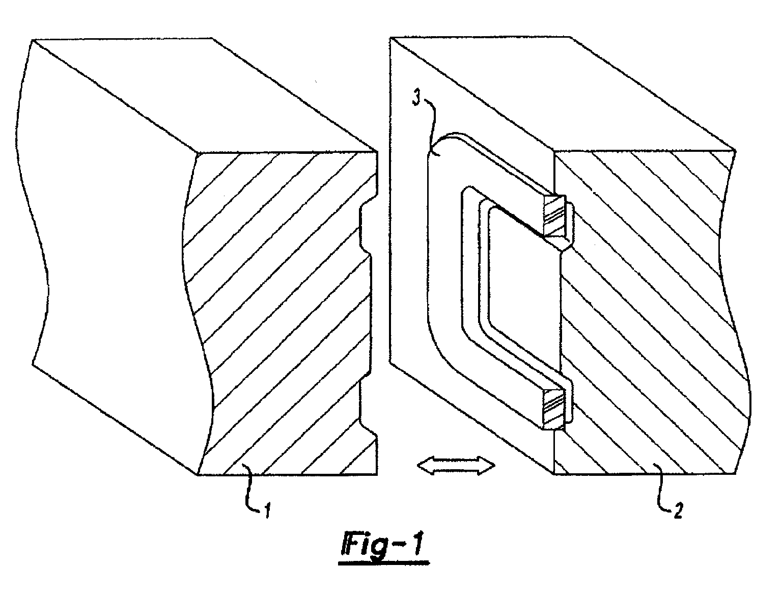
- a mould may be provided with a groove in which the foamable material may be retained with part of the foamable material projecting from the groove into the mould cavity.
- the substrate material may then be injected into the mould around the part of the foamable material that projects into the mould without causing the foamable material to foam to an undesirable extent.
- this can create a strong bond between the substrate and the foamable material.
- the groove provided in the mould may be shaped in any particular way to produce the appropriate article and may be shaped so that it retains the foamable material lightly in the mould.
- the mould may be provided with areas designed to structure the substrate in a way that the foamable material can expand across and/or through the substrate as may be desired.
- the mould temperature may be regulated to the temperature normally employed for the moulding of the substrate material and the substrate material may be moulded at its normal moulding temperature employing a typical moulding cycle.
- a moulding cycle of up to 15, more usually up to 10 seconds.
- a laminar moulding having a strong bond between the foamable material and the substrate may be obtained without substantial foaming of the foamable material. It is believed that some foaming may occur at the surface of the foamable material and that this may be beneficial and may further improve the bond between the foamable material and the substrate.
- a foamable material which would normally foam at a temperature in the range 130 to 230°C may be bonded to a substrate material such as glass filled polyamide which is injection moulded at a temperature of 200 to 220°C by the process of the present invention.
- a substrate material such as glass filled polyamide which is injection moulded at a temperature of 200 to 220°C
- this process may be performed without substantial foaming of the foamable material.
- a strong bond is formed between the foamable material and the substrate because they come into contact at the moulding temperature of the substrate at which both the foamable material and the substrate material are softened.
- a ring of foamable material is attached around the perimeter of a carrier such as in some automobile acoustic baffles
- the ring may be attached within a peripheral sandwich structure in which the outer layers are of the carrier are provided as the substrate according to the techniques of the present invention.
- a relatively small area of contact in such a sandwich structure is required to achieve a satisfactory bond between the two materials. This can lead to less foamable material being required leading to savings of the costly foamable material.
- the present invention is applicable to many different materials and moulding processes it is particularly applicable when the substrate is a thermoplastic material.
- the substrate may be foamable or unfoamable and the preferred moulding process may be either injection moulding or blow moulding.
- laminar mouldings can be produced using temperatures for the moulding of the substrate which would typically cause the foamable material to foam. Accordingly if the materials are selected appropriately we have found that a moulding cycle in terms of temperature and time can be developed in which the substrate can be moulded into contact and around the foamable material in a manner that develops a secure bond between the two materials without the foamable material foaming.
- the piece of foamable that is placed in the mould may be produced by any suitable process. Extrusion, callending and cutting or die stamping are examples of production techniques that may be used. The preferred technique will depend upon the shape and size of piece of foamable material that is required. Where the foamable material is to be attached to the perimeter of a substrate such as is required in the production of automobile acoustic baffles and may be required in automobile structural reinforcement die cutting is a particularly useful technique.
- the laminar moulding is frequently mounted in the vehicle body shell (sometimes) known as "body in white".
- the body shell is then passed through a corrosion dipping bath where an anticorrosion material is deposited on the metal, typically the deposition is electrolytic and the coating process is often known as the e-coat process.
- the anticorrosion coating is dried and baked in an oven.
- the foamable material is formulated so that foaming will take place at the temperatures employed in the oven so that an additional foaming step is not required.
- the part is therefore mounted in the body in white in such a way that leaves a clearance between the extremity of the part and the metal to allow flow and deposition of the anticorrosion material.
- the gap formed by this clearance is then filled by the foaming of the foamable material in the oven. It is important that once foamed the foamable material bonds securely to the carrier material (substrate) and also bonds to the metal of the body shell. In order to ensure this happens the clearance has traditionally been of the order of 3 millimetres. We have found however that the improved bonding between the foamable material and the substrate that is achieved by the process of the present invention allows comparable performance to be obtained using less foamable material and with a 5 millimetre clearance. The larger clearance permitting easier flow of the anticorrosion fluid and hence better cover of the metal and less corrosion.
- means for attachment of the part to the vehicle body may be formed as an integral part of the moulding process.
- clips adapted for receipt within the metal frame of the vehicle may be integrally moulded with the substrate.
- the techniques of the present invention are applicable to the production of laminar mouldings in which the substrate is produced by injection moulding or blow moulding the preferred technique depending upon the article to be produced.
- the invention provides a process for the production of mouldings comprising a substrate bonded to a foamable material wherein
- the substrate material surrounds substantially all of the part of the foamable material that projects into the cavity of the mould.
- the part of the foamable material that is held within the walls of the mould is no more than 10 millimetres long and is preferably from 2 to 10 millimetres, more preferably 2 to 5 millimetres resulting in a layer of exposed foamable material of that length after moulding.
- the temperature at which the substrate material is introduced into the mould depends upon the nature of the substrate but for glass reinforced polyamide or polypropylene temperatures in the range 180°C to 235°C are preferred. Foamable materials preferably foam at a temperature in the range 135 to 180°C.
- the moulding cycle should preferably be completed in less than 15 seconds, preferably less than 10 seconds.
- the techniques of the present invention have a wide range of uses.
- One preferred use is in the production of acoustic baffles for automobiles where the foamable material is such as to produce a highly expanded soft foam typically from polymers such as ethylene unsaturated ester copolymers typically ethylene vinyl acetate copolymers and/or ethylene acrylate copolymers.
- a particularly preferred material is an olefinic polymer-based acoustic foam, and more particularly an ethylene based polymer.
- the foamable material is based on ethylene copolymer or terpolymer that may contain a C 3 to C 8 alpha-olefin comonomer.
- particularly preferred polymers include ethylene vinyl acetate copolymers, ethylene acrylate copolymers, EPDM, or mixtures thereof.
- Other examples of preferred foam formulations that are commercially available include polymer-based materials commercially available from L&L Products, inc. of Romeo, Michigan, under the designations as L-2105, L-2100, L-7005 or L-2018, etc.
- One such foam includes an open-cell polymeric base material, such as an ethylene-based polymer which, when compounded with appropriate ingredients (typically a blowing and curing agent), expands and cures in a reliable and predictable manner upon the application of heat or the occurrence of a particular ambient condition.
- an open-cell polymeric base material such as an ethylene-based polymer which, when compounded with appropriate ingredients (typically a blowing and curing agent), expands and cures in a reliable and predictable manner upon the application of heat or the occurrence of a particular ambient condition.
- the acoustic foam is usually initially processed as a flowable thermoplastic material before curing. It will preferably cross-link upon curing, which makes the material resistant to further flow or change of final shape.
- the material can be formed of other materials (e.g., foams regarded in the art as structural foams) provided that the material selected is heat-activated or otherwise activated by an ambient condition (e.g. moisture, pressure, time or the like) and cures in a predictable and reliable manner under appropriate conditions for the selected application.
- an ambient condition e.g. moisture, pressure, time or the like
- Some other possible materials include, but are not limited to, polyolefin materials, copolymers and terpolymers, phenol/formaldehyde materials, phenoxy materials, and polyurethanes.
- U.S. Patent Nos. 5,266,133; 5,766,719; 5,755,486; 5,575,526; 5,932,680; and WO 00/27920 describe suitable materials.
- the desired characteristics of the resulting foam include relatively low glass transition point, and good corrosion resistance properties. In this manner, the material does not generally interfere with the materials systems employed by automobile manufacturers. Moreover, it will withstand the processing conditions typically encountered in the manufacture of a vehicle, such as the e-coat priming, cleaning and degreasing and other coating processes.
- a consideration involved with the selection and formulation of the material is the temperature at which a material reaction or expansion, and possibly curing, will take place. For instance, in most applications, it is undesirable for the material to be reactive at room temperature or otherwise at the ambient temperature in a production line environment. More typically, the material becomes reactive at higher processing temperatures, such as those encountered in an automobile assembly plant, when the material is processed along with the vehicle components at elevated temperatures or at higher applied energy levels, e.g., during e-coat preparation steps.
- temperatures encountered in an automobile e-coat operation may be in the range of about 145° C to about 210°C
- primer, filler and paint shop applications are commonly about 93.33°C or higher.
- the material is therefore selected according to the performance required in these operations. If needed, blowing agent activators can be incorporated into the composition to cause expansion at required temperatures.
- suitable expandable foams have a range of expansion ranging from approximately 100 to over 1000 percent.
- the level of expansion of the acoustical foam may be to as high as 1500 percent or more.
- the sound absorption material is provided in an encapsulated or partially encapsulated form, for instance an expandable foamable material is encapsulated or partially encapsulated in an adhesive shell.
- the sound absorption material may include a melt-flowable material such as that disclosed in U.S. Patent No. 6,030,701.
- the substrate is preferably an unfoamable material that supports the foamable material.
- the substrate is a harder higher melting thermoplastic such as polyamide, which may be filled usually with glass fibre, or polypropylene. Both these materials require higher temperatures for moulding than are required to foam the lower melting foamable material used in acoustic baffles but the techniques of the present invention allow the laminar moulding to be produced without causing undesirable foaming of the foamable material.
- the present invention may also be used in the production of parts for the structural reinforcement of hollow sections in automobiles or other transportation systems such as railroad and aircraft.
- the outer foamable layer is generally a rigid reinforcing thermosetting layer such as a foamable epoxy resin or a foamable polyurethane which may be a blocked polyurethane.
- the foamable material is generally supported on a rigid reinforcing carrier or substrate.
- the foamable material serves two main functions, it will expand across the space between the reinforcing member and the interior of the hollow section and will bond to some or all of the interior walls of the hollow section.
- expandable adhesive material means that the material can be activated to both expand (typically foam) and to act as an adhesive.
- the expandable material to expand and fill a gap between the reinforcing member and a hollow structure it is designed to reinforce and to bond to selected internal surfaces of the hollow structure.
- the expandable adhesive must expand at the desired temperature and be sufficiently adhesive to firmly bond the reinforcing member inside the vehicle structure. Once foamed it should be sufficiently strong that it does not contribute any weakness to the overall reinforcing effect provided.
- the expandable adhesive material Prior to activation, is preferably dry and not tacky to the touch, since this facilitates shipping and handling and prevents contamination.
- foamable materials include foamable epoxy-base resins and examples of such materials are the products L5206, L5207, L5208 and L5209, which are commercially available from L & L Products of Romeo Michigan USA, and Core 5204, 5206, 5205 and 5208 available from Core Products, France, France.
- the product should be chosen according to the rate of expansion and foam densities required. It is further preferred that it expand at the temperatures experienced in the electrocoat baking oven, typically 160°C to 185°C.
- the carrier or a substrate is usually formed from a rigid polymer such as glass fibre reinforced polyamide or polypropylene.
- Glass fibre reinforced polyamide and polypropylene both require a higher temperature for moulding then the temperature required to foam the lower melting thermosetting epoxy or polyurethane material.
- the injection moulding or blow moulding technique of the pesent invention allows the laminar structure to be formed without causing undesirable foaming of the foamable material.
- Reinforcing members for simple cross sections may be prepared by blow moulding whilst injection moulding may be required for more complex structures.
- the substrate may be of metal or thermoplastics; where injection moulding is used thermoplastics are preferred.
- Polyamides particularly glass filled polyamides are suitable materials due to their high strength to weight ratio. It is preferred that the moulding is provided with means enabling fluid drainage when the part is in place and the foamable material has foamed. For example, holes may be provided in the moulding to allow the drainage of water, which may condense in the structure over time,
- the invention is applicable to the production of a wide variety of materials it is particularly suitable for the production of reinforcing parts or acoustic insulating parts for automobiles, aircraft, ships, trains and other vehicles.
- the invention is also useful in the provision of materials useful in the construction industry.
- Structural reinforcement can be provided by the provision of a reinforcing member within a hollow structure such as part of an automotive frame.
- the reinforcing member may comprise a core, typically a hollow core carrying a structural adhesive foam.
- the foam is expanded when heated to bridge the small gap between the core and the hollow structure so that the core is bonded to the hollow structure.
- the nature of the structural adhesive foam is chosen so that it expands at the temperatures used to bake the coating that is applied to the hollow structure during the e-coat anti-corrosion coating technique widely used in the automobile industry.
- Crash protection where the prevention of vehicle body deformation is important to provide protection for the occupants.
- Energy absorption to enhance performance after yield.
- the reduction of flexing or body movement in the vehicle structure particularly to improve durability and reduce stress cracking and the point mobility problems requiring the reduction of resonance by the provision of stiffening.
- the need for reinforcement is present irrespective of the materials that are used to produce the vehicle structure and the need varies from material to material according to the nature of the reinforcement that is being provided.
- the reinforcing parts can also reduce the noise created by the motion of a vehicle by having a sound deadening effect as a result of blocking air paths in cavities.
- the reinforcing parts are typically placed in the body in white in the same manner as described in relation to acoustic baffles. Accordingly comparable performance in relation to the electrocoat process is required.
- the reinforcing structures are preferably provided within hollow sections prior to the electrocoat. It is therefore important that the reinforcing structure have minimal impact on the operation and efficiency of the electrocoat process.
- the structural reinforcing member needs to be located within the hollow section to be reinforced in a manner that enables satisfactory performance of the e-coat process without undesirable movement of the structural reinforcing member.
- Various means of attachment can be provided for example means such as clips may be moulded in the substrate which can be clipped into holes formed in the walls of the hollow section other than the wall or walls which constitute the external panel.
- attachment means such as clips may be formed in the walls of the hollow section, other than the external panel, which can fit into holes in the core of the reinforcing member.
- the structural reinforcing member may be provided with small lugs, which enable it to stand away from the interior walls of the hollow structure. In this way fastening devices may not be required and the area of contact between the structural reinforcing member and the interior walls of the frame of the vehicle is minimized.
- the clearance between the extremity of the reinforcing member and the interior walls of the hollow section should be wide enough to enable the liquid used in the electrocoat bath to flow between the reinforcing member and the interior walls of the sections of the vehicle in sufficient quantity to enable an effective anti-corrosion coating to be deposited.
- the clearance must not be too wide since this can result in a lack of rigidity in the structure when the expandable adhesive is foamed to bond the structural reinforcing member to the walls of the hollow section other than the external panel.
- the clearance be no more than 1 centimetre and is more preferably 3 to 10 millimetres.
- the clearance around the whole structure enables a more uniform foam structure to be obtained.
- the techniques of present invention can enable a wider gap to be provided for a comparable amount of foamable material
- the dimensions of the rigid reinforcing member and the thickness, location and nature of the expandable material are important for the achievement of the desired structural reinforcement.
- the exterior shape of the reinforcing member should conform substantially to the cross section of the section of the structure it is designed to reinforce.
- the shape of the reinforcing member may vary along its length as the dimensions of the cross section of the structure change.
- the size of the reinforcing member induding the expandable adhesive material should be such that there is a small clearance between the extremity of the reinforcing member and the interior walls of the structure to be reinforced to allow for passage of the electrocoat fluid.
- the foam should contact and bond to other surfaces of the hollow structure so that the rigid reinforcing member is held firmly within the structure.
- the reinforcing member may have a cellular, honeycomb or ribbed internal structure to provide reinforcement along several different axes and this structure may be provided in the moulding of the substrate.
- the member may also be provided with holes that will allow the foamable material to expand through the holes to provide an effective bond between the substrate and the automobile frame.
- the mould When closed the mould is as shown in Figure 2 with a cavity (4) around the foamable material.
- the substrate material (5) may then be injected into the mould through the injection point (not shown) to produce the structure shown in Figure 3.
- Figure 4 is a cross section of a typical moulding produced and Figure 5 shows an acoustic baffle precursor produced according to the invention provided with clips (6) for attachment to the interior of a hollow component of a vehicle.
- Figure 6 shows the product after foaming showing the foam (7).
- Figure 7 shows an over moulded baffle produced according to the present invention in which the substrate (8) around the foamable materials (9) is formed with holes (10) through which the foamable material can expand and, in this way, ensure a greater covering of a foam around and on the perimeter of the substrate.
- Figure 8 shows how a mould may be constructed to enable the production of a baffle as shown in Figure 7.
- Figure 8 shows the mould containing the foamable material (9) but without the over moulded substrate material and providing a space (11) for the provision of the substrate material.
- Figure 9 shows the mould also containing the over moulded substrate material.
Landscapes
- Engineering & Computer Science (AREA)
- Mechanical Engineering (AREA)
- Manufacturing & Machinery (AREA)
- Combustion & Propulsion (AREA)
- Structural Engineering (AREA)
- Chemical & Material Sciences (AREA)
- Architecture (AREA)
- Transportation (AREA)
- Body Structure For Vehicles (AREA)
- Vehicle Interior And Exterior Ornaments, Soundproofing, And Insulation (AREA)
- Blow-Moulding Or Thermoforming Of Plastics Or The Like (AREA)
- Soundproofing, Sound Blocking, And Sound Damping (AREA)
- Laminated Bodies (AREA)
- Moulds For Moulding Plastics Or The Like (AREA)
- Injection Moulding Of Plastics Or The Like (AREA)
Abstract
Description
Claims (25)
- A process for the production of laminar mouldings comprising a layer of a foamable material attached to a substrate wherein a piece of the foamable material is held within the walls of a mould so that part of the piece of foamable material projects into the mould cavity and the substrate is moulded around the foamable material in the mould at a temperature above the temperature at which the foamable material normally foams whereby the foamable material adheres to the substrate during the moulding process and remains unfoamed.
- A process according to Claim 1 in which the moulding process is injection moulding.
- A process according to Claim 1 in which the moulding process is blow moulding.
- A process according to any of the preceding Claims wherein the foamable material is such as to produce a highly expanded soft foam.
- A process according to Claim 4 in which the foamable material is an ethylene unsaturated ester copolymer.
- A process according to Claim 5 in which the unsaturated ester is vinyl acetate and/or an acrylate ester.
- A process according to any of the preceding Claims in which the expandable material has a level of expansion from 100 to 1500%.
- A process according to any of Claims 1 to 3 in which the foamable material is a reinforcing thermosetting material.
- A process according to Claim 8 in which the foamable material is a heat activated adhesive material.
- A process according to Claim 8 or Claim 9 in which the reinforcing thermosetting layer is a foamable epoxy resin or a foamable polyurethane.
- A process according to any of the preceding Claims in which prior to activation, the foamable material is dry and not tacky to the touch.
- A process according to any of the preceding Claims in which the substrate is an unfoamable material.
- A process according to Claim 12 in which the substrate is a polyamide, which may be fibre filled or polypropylene.
- A process for the production of mouldings comprising a substrate bonded to a foamable material whereini) a piece of foamable material is placed within a mould whereby it is partially retained within the walls of the mould and partially projects into the cavity of the mould;ii) the mould is closed and a positive pressure is applied to the mould to hold the part of the foamable material within the walls of the mould;iii) the substrate material is introduced into the mould at a temperature above the softening and foaming temperature of the foamable material in a manner that it surrounds and bonds to at least part of the part of the foamable material that projects into the cavity of the mould;iv) the moulding cycle is completed and the two component moulding removed.
- A process according to Claim 14 in which up to 10 millimetres of foamable material project into the mould.
- A process according to Claim 15 in which from 2 to 5 millimetres of foamable material project into the mould.
- A process according to any of Claims 14 to 16 in which the part of the foamable material held within the mould cavity is no more than 10 millimetres long.
- A process according to any of Claims 14 to 17 in which the foamable material foams at a temperature in the range 135 to 185°C.
- A process according to any of Claims 14 to 18 in which the substrate material is injected at a temperature in the range 180°C to 235°C.
- A process according to any of Claims 14 to 19 in which the moulding cycle is up to 15 seconds.
- A process according to Claim 20 in which the moulding cycle is up to 10 seconds.
- A multilayer moulding comprising a foamable material part of which is sandwiched between two layers of a substrate and part of which projects beyond the substitute, the foamable material foaming at a temperature below the softening point of the substrate wherein from 2 to 10 millimetres of the foamable material project beyond the substrate.
- A multilayer moulding according to Claim 22 in which the sandwich structure contains from 2 to 10 millimetres of the foamable material.
- The use of a multilayer moulding according to Claim 22 or Claim 23 for the provision of acoustic baffles in hollow structures.
- The use of a multilayer moulding according to Claim 22 or Claim 23 for the provision of structural reinforcement in hollow structures.
Applications Claiming Priority (2)
| Application Number | Priority Date | Filing Date | Title |
|---|---|---|---|
| GB0413404A GB2415162A (en) | 2004-06-15 | 2004-06-15 | Improvements in or relating to laminar mouldings |
| GB0413404 | 2004-06-15 |
Publications (2)
| Publication Number | Publication Date |
|---|---|
| EP1607204A2 true EP1607204A2 (en) | 2005-12-21 |
| EP1607204A3 EP1607204A3 (en) | 2006-05-31 |
Family
ID=32749965
Family Applications (1)
| Application Number | Title | Priority Date | Filing Date |
|---|---|---|---|
| EP05076316A Withdrawn EP1607204A3 (en) | 2004-06-15 | 2005-06-06 | Manufacture of laminar mouldings |
Country Status (5)
| Country | Link |
|---|---|
| US (1) | US20050285292A1 (en) |
| EP (1) | EP1607204A3 (en) |
| JP (1) | JP2006123506A (en) |
| CN (1) | CN1748999A (en) |
| GB (1) | GB2415162A (en) |
Cited By (8)
| Publication number | Priority date | Publication date | Assignee | Title |
|---|---|---|---|---|
| WO2010015645A1 (en) * | 2008-08-05 | 2010-02-11 | Sika Technology Ag | Baffle |
| WO2010040499A1 (en) * | 2008-10-09 | 2010-04-15 | Zephyros Inc | Provision of inserts |
| WO2010069804A1 (en) * | 2008-12-19 | 2010-06-24 | Basf Se | Method for producing a composite component by multi-component injection molding |
| WO2012143305A1 (en) * | 2011-04-21 | 2012-10-26 | Zephyros Inc | Improvements in or relating to baffles |
| US9586363B2 (en) | 2013-10-04 | 2017-03-07 | Zephyros, Inc. | Method and apparatus for adhesion of inserts |
| US9796891B2 (en) | 2014-08-11 | 2017-10-24 | Zephyros, Inc. | Panel edge enclosures |
| US11155673B2 (en) | 2015-11-12 | 2021-10-26 | Zephyros, Inc. | Controlled glass transition polymeric material and method |
| US12280582B2 (en) | 2014-08-14 | 2025-04-22 | Zephyros, Inc | Reformable epoxy resin for composites |
Families Citing this family (29)
| Publication number | Priority date | Publication date | Assignee | Title |
|---|---|---|---|---|
| GB2375328A (en) | 2001-05-08 | 2002-11-13 | L & L Products | Reinforcing element for hollow structural member |
| US6793274B2 (en) | 2001-11-14 | 2004-09-21 | L&L Products, Inc. | Automotive rail/frame energy management system |
| US7043815B2 (en) * | 2002-01-25 | 2006-05-16 | L & L Products, Inc. | Method for applying flowable materials |
| US7318873B2 (en) | 2002-03-29 | 2008-01-15 | Zephyros, Inc. | Structurally reinforced members |
| US7169344B2 (en) | 2002-04-26 | 2007-01-30 | L&L Products, Inc. | Method of reinforcing at least a portion of a structure |
| GB0211775D0 (en) | 2002-05-23 | 2002-07-03 | L & L Products Inc | Multi segment parts |
| GB0300159D0 (en) | 2003-01-06 | 2003-02-05 | L & L Products Inc | Improved reinforcing members |
| US7249415B2 (en) | 2003-06-26 | 2007-07-31 | Zephyros, Inc. | Method of forming members for sealing or baffling |
| US7784186B2 (en) | 2003-06-26 | 2010-08-31 | Zephyros, Inc. | Method of forming a fastenable member for sealing, baffling or reinforcing |
| US7469459B2 (en) | 2003-09-18 | 2008-12-30 | Zephyros, Inc. | System and method employing a porous container for sealing, baffling or reinforcing |
| GB2415658A (en) | 2004-06-21 | 2006-01-04 | L & L Products Inc | An overmoulding process |
| US7374219B2 (en) | 2004-09-22 | 2008-05-20 | Zephyros, Inc. | Structural reinforcement member and method of use therefor |
| US20060065483A1 (en) * | 2004-09-29 | 2006-03-30 | L&L Products, Inc. | Baffle with flow-through medium |
| GB0506404D0 (en) * | 2005-03-30 | 2005-05-04 | L & L Products Inc | Improvements in or relating to components |
| US7494179B2 (en) | 2005-04-26 | 2009-02-24 | Zephyros, Inc. | Member for baffling, reinforcement or sealing |
| US7503620B2 (en) | 2005-05-12 | 2009-03-17 | Zephyros, Inc. | Structural reinforcement member and method of use therefor |
| US7926179B2 (en) | 2005-08-04 | 2011-04-19 | Zephyros, Inc. | Reinforcements, baffles and seals with malleable carriers |
| GB0600901D0 (en) | 2006-01-17 | 2006-02-22 | L & L Products Inc | Improvements in or relating to reinforcement of hollow profiles |
| DE102006032480A1 (en) * | 2006-07-13 | 2008-01-17 | Daimler Ag | Insert element for a hollow body and method for inserting the insert element in the hollow body |
| TW200824884A (en) * | 2006-12-14 | 2008-06-16 | Snyang Yu Entpr Co Ltd | Molding process of in-mold thin film bonding |
| EP2330019A1 (en) * | 2009-12-04 | 2011-06-08 | Sika Technology AG | Baffle reverse molding |
| GB201207481D0 (en) | 2012-04-26 | 2012-06-13 | Zephyros Inc | Applying flowable materials to synthetic substrates |
| CN104885148A (en) | 2012-12-21 | 2015-09-02 | Sika技术股份公司 | Insulation element, expanded isolation element, use of the isolation element and method for isolation |
| US10150897B2 (en) | 2013-04-19 | 2018-12-11 | Dow Global Technologies Llc | Adhesive compositions, manufacture and use thereof |
| BR112016007842B1 (en) | 2013-10-31 | 2022-07-12 | Sika Technology Ag | DEFLECTOR OR REINFORCEMENT ELEMENT TO SEAL AND/OR REINFORCE A CAVITY, DEFLECTOR OR EXPANDED REINFORCEMENT ELEMENT PRODUCED BY THE SAME, METHOD FOR PRODUCTION THEREOF, AND SYSTEM |
| EP3218157A1 (en) | 2014-11-14 | 2017-09-20 | Zephyros Inc. | Multi-shot injection molded method and product |
| WO2017158143A1 (en) * | 2016-03-18 | 2017-09-21 | Sika Technology Ag | Insulating element |
| US20220143879A1 (en) * | 2019-03-25 | 2022-05-12 | Zephyros, Inc. | Dual expanding foam for closed mold composite manufacturing |
| EP3967579A1 (en) * | 2020-09-14 | 2022-03-16 | Sika Technology Ag | Insulating element |
Family Cites Families (14)
| Publication number | Priority date | Publication date | Assignee | Title |
|---|---|---|---|---|
| GB1247911A (en) * | 1968-07-25 | 1971-09-29 | Ici Ltd | Process for the production of cellular articles |
| US3989781A (en) * | 1971-08-17 | 1976-11-02 | Shell Oil Company | Process for producing a fibrous reinforced thermosetting resin impregnated foamed polymeric resin article |
| US4836871A (en) * | 1986-12-02 | 1989-06-06 | Mitsubishi Yuka Badische Co., Ltd. | Manufacturing method for an expanded laminated sheet |
| US5273702A (en) * | 1988-04-12 | 1993-12-28 | Ohio Cellular Products, Inc. | Method of forming a cross linked foamed polyolefin article |
| JPH0780195B2 (en) * | 1988-05-12 | 1995-08-30 | 難波プレス工業株式会社 | Rim-molded sandwich structure and method for manufacturing the same |
| DE69217179T2 (en) * | 1991-11-28 | 1997-06-26 | Mitsui Petrochemical Ind | Method of making a composite foam article |
| JP3516816B2 (en) * | 1996-08-30 | 2004-04-05 | 株式会社ネオックスラボ | Hollow chamber blocker for hollow structure and method of manufacturing the same |
| US6146565A (en) * | 1998-07-15 | 2000-11-14 | Noble Polymers, L.L.C. | Method of forming a heat expandable acoustic baffle |
| JP2000167859A (en) * | 1998-12-02 | 2000-06-20 | Toyota Auto Body Co Ltd | Method for integrally molding skin |
| US6131897A (en) * | 1999-03-16 | 2000-10-17 | L & L Products, Inc. | Structural reinforcements |
| DE10009470B4 (en) * | 2000-02-28 | 2004-07-22 | Möller Plast GmbH | Process for producing a composite component with a foamed surface |
| US6413611B1 (en) * | 2000-05-01 | 2002-07-02 | Sika Corporation | Baffle and reinforcement assembly |
| JP2002036278A (en) * | 2000-07-25 | 2002-02-05 | Neoex Lab Inc | Foamable molding |
| GB2375328A (en) * | 2001-05-08 | 2002-11-13 | L & L Products | Reinforcing element for hollow structural member |
-
2004
- 2004-06-15 GB GB0413404A patent/GB2415162A/en not_active Withdrawn
-
2005
- 2005-06-06 EP EP05076316A patent/EP1607204A3/en not_active Withdrawn
- 2005-06-13 US US11/150,966 patent/US20050285292A1/en not_active Abandoned
- 2005-06-15 CN CN200510106718.XA patent/CN1748999A/en active Pending
- 2005-06-15 JP JP2005175148A patent/JP2006123506A/en active Pending
Cited By (13)
| Publication number | Priority date | Publication date | Assignee | Title |
|---|---|---|---|---|
| US8668046B2 (en) | 2008-08-05 | 2014-03-11 | Sika Technology, AG | Baffle |
| EP2154051A1 (en) * | 2008-08-05 | 2010-02-17 | Sika Technology AG | Baffle |
| WO2010015645A1 (en) * | 2008-08-05 | 2010-02-11 | Sika Technology Ag | Baffle |
| WO2010040499A1 (en) * | 2008-10-09 | 2010-04-15 | Zephyros Inc | Provision of inserts |
| CN102232100A (en) * | 2008-10-09 | 2011-11-02 | 泽菲罗斯公司 | Supply of inserts |
| WO2010069804A1 (en) * | 2008-12-19 | 2010-06-24 | Basf Se | Method for producing a composite component by multi-component injection molding |
| US8691127B2 (en) | 2008-12-19 | 2014-04-08 | Basf Se | Method for producing a composite component by multi-component injection molding |
| WO2012143305A1 (en) * | 2011-04-21 | 2012-10-26 | Zephyros Inc | Improvements in or relating to baffles |
| US9586363B2 (en) | 2013-10-04 | 2017-03-07 | Zephyros, Inc. | Method and apparatus for adhesion of inserts |
| US9796891B2 (en) | 2014-08-11 | 2017-10-24 | Zephyros, Inc. | Panel edge enclosures |
| US10442965B2 (en) | 2014-08-11 | 2019-10-15 | Zephyros, Inc. | Panel edge enclosures |
| US12280582B2 (en) | 2014-08-14 | 2025-04-22 | Zephyros, Inc | Reformable epoxy resin for composites |
| US11155673B2 (en) | 2015-11-12 | 2021-10-26 | Zephyros, Inc. | Controlled glass transition polymeric material and method |
Also Published As
| Publication number | Publication date |
|---|---|
| GB0413404D0 (en) | 2004-07-21 |
| JP2006123506A (en) | 2006-05-18 |
| EP1607204A3 (en) | 2006-05-31 |
| US20050285292A1 (en) | 2005-12-29 |
| CN1748999A (en) | 2006-03-22 |
| GB2415162A (en) | 2005-12-21 |
Similar Documents
| Publication | Publication Date | Title |
|---|---|---|
| EP1607204A2 (en) | Manufacture of laminar mouldings | |
| US7479246B2 (en) | Overmoulding | |
| US7374219B2 (en) | Structural reinforcement member and method of use therefor | |
| CA2424005C (en) | Structurally enhanced attachment of a reinforcing member | |
| US6502821B2 (en) | Automotive body panel damping system | |
| US6634698B2 (en) | Vibrational reduction system for automotive vehicles | |
| EP1386828B1 (en) | Attachment system and method of forming same | |
| US7255388B2 (en) | Reinforcing members | |
| EP1324910B1 (en) | Automotive pillar reinforcement system | |
| US6905745B2 (en) | Structural foam | |
| EP1364862B1 (en) | Multi segment reinforcement parts | |
| CA2424041C (en) | Hydroform structural reinforcement system | |
| US20110104413A1 (en) | Improvements in or relating to reinforcement of hollow profiles | |
| US20030057737A1 (en) | Structural reinforcement system having modular segmented characteristics | |
| WO2009049886A1 (en) | Multifunctional vehicle components |
Legal Events
| Date | Code | Title | Description |
|---|---|---|---|
| PUAI | Public reference made under article 153(3) epc to a published international application that has entered the european phase |
Free format text: ORIGINAL CODE: 0009012 |
|
| AK | Designated contracting states |
Kind code of ref document: A2 Designated state(s): AT BE BG CH CY CZ DE DK EE ES FI FR GB GR HU IE IS IT LI LT LU MC NL PL PT RO SE SI SK TR |
|
| AX | Request for extension of the european patent |
Extension state: AL BA HR LV MK YU |
|
| PUAL | Search report despatched |
Free format text: ORIGINAL CODE: 0009013 |
|
| AK | Designated contracting states |
Kind code of ref document: A3 Designated state(s): AT BE BG CH CY CZ DE DK EE ES FI FR GB GR HU IE IS IT LI LT LU MC NL PL PT RO SE SI SK TR |
|
| AX | Request for extension of the european patent |
Extension state: AL BA HR LV MK YU |
|
| 17P | Request for examination filed |
Effective date: 20061120 |
|
| AKX | Designation fees paid |
Designated state(s): AT BE BG CH CY CZ DE DK EE ES FI FR GB GR HU IE IS IT LI LT LU MC NL PL PT RO SE SI SK TR |
|
| RAP1 | Party data changed (applicant data changed or rights of an application transferred) |
Owner name: ZEPHYROS INC. |
|
| STAA | Information on the status of an ep patent application or granted ep patent |
Free format text: STATUS: THE APPLICATION IS DEEMED TO BE WITHDRAWN |
|
| 18D | Application deemed to be withdrawn |
Effective date: 20090103 |