EP1607153A1 - Method for manufacturing mold - Google Patents
Method for manufacturing mold Download PDFInfo
- Publication number
- EP1607153A1 EP1607153A1 EP04717275A EP04717275A EP1607153A1 EP 1607153 A1 EP1607153 A1 EP 1607153A1 EP 04717275 A EP04717275 A EP 04717275A EP 04717275 A EP04717275 A EP 04717275A EP 1607153 A1 EP1607153 A1 EP 1607153A1
- Authority
- EP
- European Patent Office
- Prior art keywords
- mold
- porous layer
- wax
- layer
- porous structure
- Prior art date
- Legal status (The legal status is an assumption and is not a legal conclusion. Google has not performed a legal analysis and makes no representation as to the accuracy of the status listed.)
- Granted
Links
Images





Classifications
-
- A—HUMAN NECESSITIES
- A61—MEDICAL OR VETERINARY SCIENCE; HYGIENE
- A61C—DENTISTRY; APPARATUS OR METHODS FOR ORAL OR DENTAL HYGIENE
- A61C13/00—Dental prostheses; Making same
- A61C13/20—Methods or devices for soldering, casting, moulding or melting
-
- A—HUMAN NECESSITIES
- A61—MEDICAL OR VETERINARY SCIENCE; HYGIENE
- A61F—FILTERS IMPLANTABLE INTO BLOOD VESSELS; PROSTHESES; DEVICES PROVIDING PATENCY TO, OR PREVENTING COLLAPSING OF, TUBULAR STRUCTURES OF THE BODY, e.g. STENTS; ORTHOPAEDIC, NURSING OR CONTRACEPTIVE DEVICES; FOMENTATION; TREATMENT OR PROTECTION OF EYES OR EARS; BANDAGES, DRESSINGS OR ABSORBENT PADS; FIRST-AID KITS
- A61F2/00—Filters implantable into blood vessels; Prostheses, i.e. artificial substitutes or replacements for parts of the body; Appliances for connecting them with the body; Devices providing patency to, or preventing collapsing of, tubular structures of the body, e.g. stents
- A61F2/02—Prostheses implantable into the body
- A61F2/28—Bones
-
- B—PERFORMING OPERATIONS; TRANSPORTING
- B22—CASTING; POWDER METALLURGY
- B22C—FOUNDRY MOULDING
- B22C7/00—Patterns; Manufacture thereof so far as not provided for in other classes
- B22C7/02—Lost patterns
-
- B—PERFORMING OPERATIONS; TRANSPORTING
- B22—CASTING; POWDER METALLURGY
- B22C—FOUNDRY MOULDING
- B22C9/00—Moulds or cores; Moulding processes
- B22C9/02—Sand moulds or like moulds for shaped castings
- B22C9/04—Use of lost patterns
-
- B—PERFORMING OPERATIONS; TRANSPORTING
- B22—CASTING; POWDER METALLURGY
- B22C—FOUNDRY MOULDING
- B22C9/00—Moulds or cores; Moulding processes
- B22C9/02—Sand moulds or like moulds for shaped castings
- B22C9/04—Use of lost patterns
- B22C9/043—Removing the consumable pattern
-
- B—PERFORMING OPERATIONS; TRANSPORTING
- B22—CASTING; POWDER METALLURGY
- B22C—FOUNDRY MOULDING
- B22C9/00—Moulds or cores; Moulding processes
- B22C9/22—Moulds for peculiarly-shaped castings
Definitions
- the present invention relates to a method for manufacturing a mold used for an investment casting.
- an artificial dental root (hereinafter, referred to as an implant member) for artificial biomaterial transplantation, a porous layer having a porous structure is formed on the surface in order to increase a surface area.
- a method for forming a porous layer having a porous structure on a surface the following two methods have been used, that is, (1) a method carrying out a laser beam machining on the surface of a metallic body (or an alloy body), and (2) a method piling up thin sheets made with metallic materials having many pores while three-dimensionally controlling a hole shape in the porous structure, which is described in Japanese Patent Application Laid-Open No. H10-155823.
- the manufacturing method (1) although the metallic body (or the alloy body) having a porous structure only on the surface, that is, a rough surface, can be easily obtained, there was the problem that a porous layer having a three-dimensional porous structure cannot be obtained. Further, in the case of a metal (or an alloy) having high melting point, there were problems that a high output laser beam machine and a long processing time were necessary for the laser beam machining.
- the above-mentioned porous layer is made by a casting method capable of comparatively easy manufacture.
- a porous article is manufactured by the casting method, projections formed on an inner surface of a mold constitute pores of a porous article.
- the head of each projection in order to take out a cast body from the mold, the head of each projection must be narrower than its base. Therefore, as for the pore shape of the porous article obtained by the casting method, a bottom part of the pore is narrower than an opening part of the hole.
- one like a golf ball having a concave dimple on the surface could be cast, but there was a problem to make a cast article having a complicated three-dimensional porous structure on the surface by casting.
- the present invention solves the above-mentioned problems, and the primary objective is to provide a method for manufacturing a mold, wherein a porous body can be made.
- One embodiment of the present invention is as follows. That is, a layer of combustible powdery particles is formed around a wax mold, which is a lost pattern. A film of a ceramic precursor slurry is coated around the wax mold having a layer of powdery particles formed thereon. Then, a resultant product is heated to dewax the wax mold, and thereafter, the slurry film is fired to burn and vanish the powdery particles inside the slurry film, and to form a shell. Thereby, the mold having a porous layer on the surface of the cavity of the shell can be made, wherein the porous layer has a three-dimensional porous structure.
- Another embodiment of the present invention is as follows. That is, a layer of combustible powdery particles is formed on an inner surface of a female mold for forming a wax mold, which is a lost pattern. A wax material is injected into the female mold, and the wax mold is formed around which has the layer of the powdery particles. Then, a film of a ceramic precursor slurry is coated around the wax mold. Then, after dewaxing the wax mold by heating, the powdery particles inside of the slurry film is burned and vanished by firing the slurry film, and a shell is formed. Thereby, the mold having a porous layer on the surface of the cavity of the shell can be manufactured, wherein the porous layer has a three-dimensional porous structure.
- Another embodiment of the present invention is a mold made by any one of the above-described methods for manufacturing the mold, and the mold has a porous layer on the surface of the cavity of a shell, wherein the porous layer has a three-dimensional porous structure.
- another embodiment of the present invention is a method for manufacturing a cast article by the steps of pouring a molten metal into the cavity of a mold obtained by any one of the above-described methods for manufacturing the mold, cooling the molten metal, and removing the shell.
- a cast article having a porous layer at least on the surface thereof, wherein the porous layer has a three-dimensional porous structure.
- another embodiment of the present invention is a cast article manufactured by any one of the above-described methods.
- the cast article having a porous layer at least on the surface thereof, wherein the porous layer has a three-dimensional porous structure, and preferably to manufacture an implant member, a catalyst carrier, a turbine rotor, a turbine blade, or the like.
- Figure 1 illustrates a flow chart of a casting method of a cast article according to one preferred embodiment of the present invention.
- the casting method of the cast article according to the present preferred embodiment uses an investment casting method (a lost wax method).
- the method comprises steps of first manufacturing a metallic mold (a female mold) having a cavity with a predetermined shape (Process A), pouring a wax material into the metallic mold by a method such as an injection molding or the like (Process B), and taking out a wax molding body from the metallic mold after hardening the wax material (Process C).
- a wax mold (a male mold) 21 which is a lost pattern as illustrated in Figure 2, can be obtained using the wax molding body.
- two kinds or more of wax molding bodies may be formed if necessary, to thereby obtain the desired wax mold 21 by assembling those.
- the wax mold 21 comprises an ingate, a runner and a sprue, which are used in the below-described casting although not illustrated in the drawings. Further, a plurality of wax molds may be integrated into a tree shape or a cluster shape.
- the wax material in this case includes not only waxes themselves but also whole resins (plastics).
- a layer 31 consisting of many combustible powdery particles 32 is formed at a desired part around the wax mold 21 (Process D).
- a layer 31 consisting of many combustible powdery particles 32 is formed at a desired part around the wax mold 21 (Process D).
- many powdery or granular combustible powdery particles 32 are adhered at a part around the mold wax 21, wherein the part is desired to have a three-dimensional porous structure.
- the porous structure 33 whose pores are arranged randomly, or the porous structure 33 whose pores are aligned in a predetermined direction, by controlling an arrangement of each powdery particle 32 adhered around the wax mold 21. Further, the pore size and shape of the porous structure 33 can be controlled by changing the size and shape of the powdery particles 32. Furthermore, the thickness of a porous layer 74 of a mold 70 as described below, that is, the thickness of a porous layer 94 of a cast article 90 can be controlled by controlling the thickness of the layer 31.
- the slurry 52 is dried, and then, a slurry film 51 is coated around the wax mold 30 (Process E).
- the slurry 52 also enters into a part of the porous structure 33 of the layer 31, that is, enters into a void space of the layer 31, and all the powdery particles 32 are covered with the slurry film 51.
- a dipping method, a spraying method, or a coating method can be used, but the dipping method is preferable since it has sufficient permeability of the slurry 52 to the inside of the layer 31.
- the film thickness of the slurry film 51 is controlled so as to have a desired thickness by repeating operations of adhering and drying of the slurry 52.
- the wax mold 30 having the slurry film 51 coated thereon is subjected to a heat and pressure treatment at 4 to 8 atmospheres and at 100 to 180°C, preferably at 140 to 160°C, to thereby dewax the wax mold (Process F).
- the wax material is melted, and the wax mold 21 is lost to become a cavity 61, to thereby obtain a mold precursor (a mold preformed body) 60 having the cavity 61 inside the slurry film 51.
- each powdery particle 32 inside the slurry film 51 does not vanish but remains, and the shape of each powdery particle 32 (the layer 31) is kept.
- the mold precursor 60 is subjected to a firing treatment at a temperature of 900 to 1,300°C (Process G), and as illustrated in Figure 7, the slurry film 51 is fired to be hardened to form a shell 71.
- a firing treatment at a temperature of 900 to 1,300°C (Process G), and as illustrated in Figure 7, the slurry film 51 is fired to be hardened to form a shell 71.
- each combustible powdery particle 32 remaining in the mold precursor 60 is burned and vanished gradually from a side facing to the cavity 61 toward the inner side of the mold precursor 60, before forming the shell 71.
- a portion occupied by each powdery particle 32 becomes a fine void space 75 by this burning.
- a gas g generated while burning a certain powdery particle 32 reaches to the cavity 61 of the mold precursor 60 passing through the adjacent fine void space 75, and then exhausted to the outside of the mold precursor 60.
- the particle material is selected so that the temperature is not more than the firing temperature of the slurry film 51, preferably lower than the firing temperature of the slurry film 51 by 90°C or more, and more preferably lower than the firing temperature of the slurry film 51 by 100°C or more.
- the mold 70 made of ceramics having a cavity 72 inside the shell 71, wherein the cavity 72 is comprised of the cavity 61 having the same shape as the wax mold 21 and a group of the fine void space 75 having the same shape as each powdery particle 32 (the layer 31). That is, the mold 70 has the porous layer 74 on the surface 76 of the cavity of the shell 71, wherein the porous layer 74 has a three-dimensional porous structure 73.
- a molten metal 81 is poured into the cavity 72 of the mold 70 to be cast (Process H). At this time, since each fine void space 75 links one another, the molten metal 81 enters into up to every hole and corner of each fine void space 75. Then, the molten metal 81 is cooled (Process I) and then, the casting is completed. Thereby, a cast body 82 is formed in the mold 70.
- a pouring casting method, a centrifugal casting method, a suction casting method (low pressure casting), or the like can be applicable.
- the shell 71 is subjected to blast cleaning to remove the shell 71 (Process J).
- blast cleaning to remove the shell 71
- a cast article 90 as an integrated article having a porous layer 94 at least on the surface thereof can be obtained, wherein the porous layer 94 has a three-dimensional porous structure 93.
- any one of a sand blast method, a shot blast method, and a water jet method (spraying of high-pressure water) may be used.
- a shakeout method can be used as a method for removing the shell 71 other than the blast cleaning.
- the powdery or granular combustible powdery particles 32 it is not especially limited if it can be completely (or substantially completely) burned and vanished at the temperature of the firing treatment of 900 to 1,300°C.
- wood, fiber, carbon (graphite) or the like can be used.
- a method for adhering many powdery particles 32 around the wax mold 21 it is not especially limited, and for example, a method for coating an adhesive or a cohesive agent around the wax mold 21 can be used. At this time, if the adhesive or the cohesive agent is adhered around the powder particle 32 excessively, the fine void space 75 cannot be formed with sufficient accuracy, so that it is not preferable.
- the matrix of the molten metal 81 is not especially limited if it is generally used as a metal (or an alloy) for casting.
- an alloy having a relatively high melting point such as a Ti-based alloy, a Co-based alloy, a Ni-based alloy and an Al-based alloy, is preferable, and the Ti-based alloy, the Co-based alloy, and the Ni-based alloy, which are used for precision casting, are especially preferable as these alloys.
- the cast article 90 which could not be manufactured by the casting method heretofore, having the porous layer 94 on the surface thereof can be obtained, wherein the porous layer 94 has a complicated, three-dimensional porous structure 93.
- This cast article cannot be manufactured by the conventional method. That is, a porous body having the porous layer on the surface thereof can be obtained, wherein the porous layer has the three-dimensional porous structure.
- the porous layer 94 in the cast article 90 can be integrally formed with a main body, and the cast article 90 can be easily manufactured.
- the cast article 90 manufactured by the casting method according to the present preferred embodiment can be applied to a member necessary for having a large surface area, such as a carrier of a catalyst, an implant member, or the like, a rotary member or a blade member for a jet engine or a gas turbine engine, or a honeycomb member, or the like.
- the cast article 90 can be easily manufactured for a short time, as compared with the conventional manufacturing method described above.
- the carrier of the catalyst since the carrier of the catalyst has a porous layer on the surface thereof, a large amount of catalysts can be supported as compared with the conventional carriers of catalysts.
- the implant member when an implant member is cast and formed similarly, the implant member can be strongly combined with biomedical tissues since it has a porous layer on the surface thereof. Because it is generally required that the implant member has the porous layer on the surface thereof, and the cast article 90 obtained by the casing method according to the present preferred embodiment is suitable as the implant member.
- a rotor or a blade of a turbine for example, a rotary member or a blade member of a jet engine or a gas turbine engine is cast and formed similarly, since these members have a porous layer on the surface thereof, weights of these members can be reduced, and a large amount of bubble layers can be formed on the surface of each member. As a result, these bubbles exert a heat insulation effect, and thus the member can keep the sufficient high temperature strength even when it is a thin member, and the weight of the member can be reduced.
- the case of forming the wax molding body by using the metal mold is described, but it is not especially limited to the metal mold.
- a mold for forming a wax molding body any mold can be used if it is generally used for molding waxes, plastics or the like.
- a plastic mold or a wooden mold may be used.
- FIG. 10 A flow chart of the casting method of a cast article according to the other preferred embodiment of the present invention is shown in Figure 10.
- the same codes as those of Figure 1 are used in the same processes in Figure 10.
- the casting method according to the former preferred embodiment comprised the steps of forming the wax mold 21, randomly scattering many combustible powdery particles around the wax mold 21, and adhering and forming the layer 31 of the group of powdery particle 32 around the wax mold 21.
- the casting method according to the present preferred embodiment is characterized by a step of adhering and forming a layer of a group of powdery particle on the inner surface of a metal mold for forming a wax mold.
- a metal mold (a female mold) having a cavity with a predetermined shape is produced at first (Process A), as shown in Figure 10.
- a layer of many combustible powdery particles is formed on the desired part of the inner surface of the metal mold (Process D2).
- a wax material 123 is injected into a cavity 122 of a metal mold 121
- a layer 125 comprising many powdery or granular combustible powdery particles 124 is preformed, so as to be placed at a part on the inner surface of the metal mold 121, wherein the part is desired to have a three-dimensional porous structure.
- the layer 125 is preformed using an adhesion means (adhesives, mold lubricants, vaseline, lanolin or the like).
- the layer 125 may be formed as a plurality of layers if necessary.
- the powdery particles 124 the same particles as the powdery particles 32 illustrated in Figure 4 can be used.
- the wax material (wax) 123 is poured into the cavity 122, or the wax material 123 is injected into the cavity 122 by the injection molding method or the like (Process B).
- a wax molding body 120 is taken out from the metal mold 121 (Process C).
- the wax molding body 120 has a layer 126 on the surface thereof, wherein the layer 126 has a three-dimensional porous structure, and the outer surface of the layer 126 has no irregularities, that is, the height is approximately uniform, and the surface is smooth.
- the desired wax mold 101 may be obtained by repeating the processes A, D2, B and C as needed to form two kinds or more of wax molding bodies, and by assembling them.
- the wax mold 101 comprises an ingate, a runner, and a sprue, which are used in the below-described casting although not illustrated in the drawings. Further, a plurality of wax molds 101 may be integrated into a tree shape or a cluster shape.
- the wax material in this case includes not only waxes themselves but also whole resins (plastics).
- the processes E and F are carried out for the wax mold 101 in the same procedure as that of the casting method according to the former preferred embodiment, to thereby obtain a mold precursor 102 having a void space in a slurry film.
- the powdery particles 124 do not vanish but remain in the slurry film, and the shape of each powdery particle 124 (layer 125) is kept.
- the process G is carried out for the mold precursor 102 in a similar procedure to that of the casting method according to the former preferred embodiment, to thereby obtain a mold 103 made of ceramics having a cavity inside the shell, wherein the cavity is comprised of a cavity having the same shape as the wax mold 101 and a group of the fine void space having the same shape as each powdery particle 124 (the layer 125). That is, the mold 103 has a porous layer on the surface of the cavity of the shell, wherein the porous layer has a three-dimensional porous structure having a substantially uniform depth.
- the cast article 104 has a porous layer at least on the surface thereof, wherein the porous layer has a three-dimensional porous structure.
- the cast article 104 having the smooth outer surface of the porous layer is a comparatively flat integral body.
- each powdery particle 124 adhered on the inner surface of the metal mold 121 by controlling an arrangement of each powdery particle 124 adhered on the inner surface of the metal mold 121, it is possible to obtain the layer 125 having a porous structure whose pores are randomly arranged or a porous structure whose pores are aligned in a predetermined direction. Further, by changing the size and shape of the powdery particles 124, the pore size and pore shape of the layer 125 having the porous structure can be controlled. Furthermore, by controlling the thickness of the layer 125, the thickness of the porous layer of the mold 103, that is, the thickness of the porous layer of the cast article 104 can be controlled.
- the temperature of the wax material 123 is controlled to be between the softening point or more and the melting point+30°C or less.
- the viscosity of the wax material 123 is controlled, and the wax material 123 does not reach to the surface of the metal mold 121 passing through the gap between the powdery particles 124 due to the surface tension of the wax material 123.
- the injection pressure is controlled to have a suitable value so that the wax material 123 does not reach to the surface of the metal mold 121 passing through the gap between the powdery particles 124.
- the wax molding body 120 when the wax molding body 120 is taken out from the metal mold 121, it can be taken out intact in most cases when mold lubricant, vaseline, lanolin, or the like is used as the adhesion means. Meanwhile, when the adhesive is used as the adhesion means, a peeling liquid for the adhesive is poured into the gap between the metal mold 121 and the wax molding body 120, to thereby take out the wax molding body 120 after the adhesive is peeled off.
- the layer 126 formed on the surface of the wax mold 101 is formed using the inner surface of the metal mold 121, the reproducibility of the layer 126 is favorable as compared with the casting method according to the former preferred embodiment, where the layer 31 is formed by randomly scattering many powdery particles 32 on the surface of the wax mold 21.
- the outer surface (the outline) of the porous layer 94 having the three-dimensional porous structure 93 is not uniform and irregular.
- the implant member may be caught by the biomedical tissues due to the ununiform and irregular outer surface of the porous layer 94.
- the shape of the outer surface of the layer 125 becomes substantially equal to the shape of the inner surface of the metal mold 121 by pasting the layer 125 comprising the many powdery particles 124 on the inner surface of the metal mold 121 in advance.
- the outer surface of the layer 126 formed on the surface is substantially uniform and smooth.
- the cast article 104 which is finally obtained by using the wax mold 101, the outer surface of the porous layer having the porous structure is substantially uniform and smooth.
- the layer 125 consisting of many powdery particles 124 is adhered and formed on the inner surface of the metal mold 121 for forming the wax mold 101 by the adhesion means.
- the combustible powdery particles 124 constituting the layer 125 which is preformed on the inner surface of the metal mold 121
- the layer 125 can be formed on the inner surface of the metal mold 121 by only applying a magnetic field to the metal mold 121.
- the wax molding body 120 is taken out from the metal mold 121 by only the steps for pouring the wax material 123, hardening it, and stopping the application of the magnetic field to the metal mold 121.
- the wax molding body 120 can be easily taken out.
- Wax was poured at 80°C into a metal mold having a cavity with a predetermined shape. After hardening the wax, a pattern (a wax molding body) was taken out from the metal mold. The wax molding body thus obtained was shaped to have a tree shape, to thereby manufacture a wax mold.
- a spray paste was sprayed onto a part of the wax mold, wherein the part was desired to be porous, and many wood pieces having sizes of approximately 0.5 to 1.0 mm were scattered and adhered on the part sprayed with the spray paste. This work was repeated as appropriate, to thereby form a porous layer having a porous structure, wherein the porous layer had many wood pieces piled up to have a plurality of layers.
- the wax mold was heated and pressurized at 140 to 150°C and 5 to 6 atmospheres for 7 minutes to dewax the wax mold, to thereby obtain a wax precursor (a wax preformed body). Then, the wax precursor was subjected to a firing treatment at 1,100°C for 2 hours, to thereby manufacture a mold consisting of a shell obtained by firing and hardening the slurry.
- the mold was preheated at 900°C, and a molten Co-based superalloy was poured into the cavity of the mold at a molten metal temperature of 1,500°C to cast it. Then, the molten metal was cooled, to thereby manufacture a cast body in the mold.
- the mold was subjected to a sandblast treatment to remove the shell, to thereby manufacture a cast article.
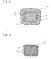
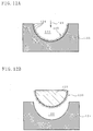
- a cast article 130 had integrally a porous layer 133 at least on the surface of a main body 131, wherein the porous layer 133 had a three-dimensional porous structure 132.
- the porous layer 133 the height of the outer surface was not uniform and the outer surface was irregular.
- Vaseline was coated on the inner surface of a metal mold having a cavity with a predetermined shape. Then, a spray paste was sprayed onto a part of the inner surface of the metal mold, wherein the part was desired to be porous, and many wood pieces having sizes of approximately 0.5 to 1.0 mm were scattered and adhered on the part sprayed with the spray paste. This work was repeated as appropriate, to thereby form a porous layer having a porous structure, wherein the porous layer had many wood pieces piled up to have a plurality of layers.
- a wax molding body thus obtained was shaped to have a tree shape to thereby manufacture a wax mold.
- a cast article was manufactured in a manner similar to Example 1 except for the use of this wax mold.
- a cast article 140 had integrally a porous layer 143 at least on the surface of a main body 141, wherein the porous layer 143 had a three-dimensional porous structure 142.
- the porous layer 143 the height of the outer surface was uniform and the outer surface was not irregular.
- the cast article 130 in Example 1 has 30% higher porosity in the porous layer 133 than that in the porous layer 143 of the cast article 140 in Example 2.
- the pore rate in a certain cross section was about 50%.
- the pore rate in a certain cross section was about 35%. Due to an irregular height of the outer surface of the porous layer 133, the cast article 130 was considered to have higher porosity than that of the cast article 140 having a uniform height of the outer surface of the porous layer 143.
- the depths of the porous layer from the uppermost surface to the deepest part were 2.08 mm and 1.96 mm, respectively, and these were considered to be substantially equal. That is, with respect to the depth of the porous layer, there was substantially no difference in both articles.
Landscapes
- Health & Medical Sciences (AREA)
- Engineering & Computer Science (AREA)
- Mechanical Engineering (AREA)
- Public Health (AREA)
- Oral & Maxillofacial Surgery (AREA)
- Veterinary Medicine (AREA)
- Life Sciences & Earth Sciences (AREA)
- Animal Behavior & Ethology (AREA)
- General Health & Medical Sciences (AREA)
- Epidemiology (AREA)
- Dentistry (AREA)
- Vascular Medicine (AREA)
- Cardiology (AREA)
- Transplantation (AREA)
- Biomedical Technology (AREA)
- Heart & Thoracic Surgery (AREA)
- Orthopedic Medicine & Surgery (AREA)
- Molds, Cores, And Manufacturing Methods Thereof (AREA)
- Moulds For Moulding Plastics Or The Like (AREA)
- Dental Prosthetics (AREA)
- Materials For Medical Uses (AREA)
- Prostheses (AREA)
- Mold Materials And Core Materials (AREA)
Abstract
Description
Claims (19)
- A method for manufacturing a mold having a porous layer having a three-dimensional porous structure on a surface of a cavity of a shell, the method comprising,a step D for forming a layer of combustible powdery particles around a wax mold, which is a lost pattern,a step E for coating a film of a ceramic precursor slurry around the wax mold having the layer of the powdery particles formed thereon,a step F for subjecting the wax mold coated with the slurry film to a heat treatment, to thereby dewax the wax mold, anda step G for firing the slurry film, to thereby burn and vanish the powdery particles in the slurry film and form a shell.
- A method for manufacturing a mold having a porous layer having a three-dimensional porous structure on a surface of a cavity of a shell, the method comprising,a step D2 for forming a layer of combustible powdery particles on the inner surface of a female mold for forming a wax mold, which is a lost pattern,a step B for pouring a wax material into the female mold, to thereby form the wax mold having the layer of the powdery particles around thereof,a step E for coating a film of a ceramic precursor slurry around the wax mold,a step F for subjecting the wax mold coated with the slurry film to a heat treatment, to thereby dewax the wax mold, anda step G for firing the slurry film, to thereby burn and vanish the powdery particles in the slurry film and form a shell.
- The method for manufacturing the mold according to claim 1 or 2, wherein the powdery particles are burned and vanished near the firing temperature of the slurry film in said step G.
- The method for manufacturing the mold according to claim 3, wherein the powdery particles are burned and vanished at a temperature lower than the firing temperature of the slurry film by 90°C or more in said step G.
- A mold manufactured by the method for manufacturing the mold according to claims 1, 3 and 4, wherein said mold has the porous layer on the surface of the cavity of the shell, and said porous layer has the three-dimensional porous structure.
- A mold manufactured by the method for manufacturing the mold according to claims 2, 3 and 4, wherein said mold has the porous layer on the surface of the cavity of the shell, and said porous layer has the three-dimensional porous structure.
- A casting method for manufacturing a cast article using the mold obtained by the method for manufacturing the mold according to claims 1, 3 and 4, the method comprising,a step H for pouring a molten metal into the cavity of the mold,a step I for cooling the molten metal, anda step J for removing the shell of the mold.
- A casting method for manufacturing a cast article using the mold obtained by the method for manufacturing the mold according to claims 2, 3 and 4, the method comprising,a step H for pouring a molten metal into the cavity of the mold,a step I for cooling the molten metal, anda step J for removing the shell of the mold.
- A casting method of the cast article according to claim 7 or 8, wherein the shell is removed by a blast cleaning method in said step J.
- A cast article manufactured by the casting method according to claim 7 or 9, wherein said article has a porous layer at least on the surface thereof, and said porous layer has a three-dimensional porous structure.
- A cast article manufactured by the casting method according to claim 8 or 9, wherein said article has a porous layer at least on the surface thereof, and said porous layer has a three-dimensional porous structure.
- An implant member manufactured by the casting method according to claim 7 or 9, wherein said member has a porous layer at least on the surface thereof, and said porous layer has a three-dimensional porous structure.
- An implant member manufactured by the casting method according to claim 8 or 9, wherein said member has a porous layer at least on the surface thereof, and said porous layer has a three-dimensional porous structure.
- A catalyst carrier manufactured by the casting method according to claim 7 or 9, wherein said carrier has a porous layer at least on the surface thereof, and said porous layer has a three-dimensional porous structure.
- A catalyst carrier manufactured by the casting method according to claim 8 or 9, wherein said carrier has a porous layer at least on the surface thereof, and said porous layer has a three-dimensional porous structure.
- A turbine rotor manufactured by the casting method according to claim 7 or 9, wherein said rotor has a porous layer at least on the surface thereof, and said porous layer has a three-dimensional porous structure.
- A turbine rotor manufactured by the casting method according to claim 8 or 9, wherein said rotor has a porous layer at least on the surface thereof, and said porous layer has a three-dimensional porous structure.
- A turbine blade manufactured by the casting method according to claim 7 or 9, wherein said blade has a porous layer at least on the surface thereof, and said porous layer has a three-dimensional porous structure.
- A turbine blade manufactured by the casting method according to claim 8 or 9, wherein said blade has a porous layer at least on the surface thereof, and said porous layer has a three-dimensional porous structure.
Applications Claiming Priority (5)
| Application Number | Priority Date | Filing Date | Title |
|---|---|---|---|
| JP2003058713 | 2003-03-05 | ||
| JP2003058713 | 2003-03-05 | ||
| JP2004023863 | 2004-01-30 | ||
| JP2004023863A JP4103812B2 (en) | 2003-03-05 | 2004-01-30 | Mold manufacturing method |
| PCT/JP2004/002708 WO2004078378A1 (en) | 2003-03-05 | 2004-03-04 | Method for manufacturing mold |
Publications (3)
| Publication Number | Publication Date |
|---|---|
| EP1607153A1 true EP1607153A1 (en) | 2005-12-21 |
| EP1607153A4 EP1607153A4 (en) | 2007-02-07 |
| EP1607153B1 EP1607153B1 (en) | 2009-12-09 |
Family
ID=32964897
Family Applications (1)
| Application Number | Title | Priority Date | Filing Date |
|---|---|---|---|
| EP04717275A Expired - Lifetime EP1607153B1 (en) | 2003-03-05 | 2004-03-04 | Method for manufacturing mold |
Country Status (8)
| Country | Link |
|---|---|
| US (3) | US7281566B2 (en) |
| EP (1) | EP1607153B1 (en) |
| JP (1) | JP4103812B2 (en) |
| KR (1) | KR100933696B1 (en) |
| CN (1) | CN1325193C (en) |
| AT (1) | ATE451187T1 (en) |
| DE (1) | DE602004024509D1 (en) |
| WO (1) | WO2004078378A1 (en) |
Cited By (3)
| Publication number | Priority date | Publication date | Assignee | Title |
|---|---|---|---|---|
| EP1760402A3 (en) * | 2005-08-30 | 2009-11-11 | United Technologies Corporation | Method for casting cooling holes |
| CN102248125A (en) * | 2011-06-25 | 2011-11-23 | 深圳技师学院 | Simplified process method of lost wax casting |
| FR3085288A1 (en) * | 2018-08-31 | 2020-03-06 | Safran Aircraft Engines | METHOD FOR MANUFACTURING A METAL ASSEMBLY FOR A TURBOMACHINE BY LOST WAX FOUNDRY |
Families Citing this family (23)
| Publication number | Priority date | Publication date | Assignee | Title |
|---|---|---|---|---|
| JP5326164B2 (en) * | 2006-09-26 | 2013-10-30 | 独立行政法人産業技術総合研究所 | Biomaterials and their production methods and applications |
| WO2008111220A1 (en) * | 2007-03-15 | 2008-09-18 | Ibiden Co., Ltd. | Process for manufacturing thermoelectric converter |
| DE102007038958A1 (en) * | 2007-08-15 | 2009-02-19 | Inocermic Gesellschaft für innovative Keramik mbH | Process for the production of implants and components by direct shaping |
| US7926542B2 (en) * | 2008-05-30 | 2011-04-19 | Xi Yang | Low stress dewaxing system and method |
| US8347485B2 (en) * | 2010-02-12 | 2013-01-08 | GM Global Technology Operations LLC | Centrifugally-cast shorted structure for induction motor rotors |
| CN102189257A (en) * | 2010-03-10 | 2011-09-21 | 钟淼芳 | Cutting tool and sintering forming method of cutting body powder thereof |
| TWI399225B (en) * | 2010-07-13 | 2013-06-21 | Univ Lunghwa Sci & Technology | Modeling method and forming method of bio-ceramic bone scaffold |
| CN102416439A (en) * | 2010-09-26 | 2012-04-18 | 东风精密铸造有限公司 | Surface treatment method for ceramic shell lost foam casting foam pattern |
| US20120085507A1 (en) * | 2010-10-08 | 2012-04-12 | Buntrock Industries, Inc. | Dewax method for investment casting |
| US8225841B1 (en) | 2011-01-03 | 2012-07-24 | James Avery Craftsman, Inc. | Central sprue for investment casting |
| US8424585B2 (en) | 2011-01-21 | 2013-04-23 | James Avery Craftsman, Inc. | Method and apparatus for creating a pattern |
| CN102266905A (en) * | 2011-07-08 | 2011-12-07 | 山东泰山钢铁集团有限公司 | Manufacturing process of part shell with location hole |
| CN102632196B (en) * | 2012-05-04 | 2015-02-11 | 刘玉满 | Lost foam casting (LFC) method without roasting by using precise paraffin wax model sample and high-performance coating shell mould |
| TWI482699B (en) * | 2012-05-21 | 2015-05-01 | Univ Nat Taipei Technology | A method for preparing inorganic green bodies with three - dimensional contours |
| CN102672104A (en) * | 2012-05-29 | 2012-09-19 | 刘翔 | Precision casting method for pouring evanescent mold through high-performance coating foam and mold laminating paraffin |
| CN102699279A (en) * | 2012-07-02 | 2012-10-03 | 安徽应流铸业有限公司 | Large-size impeller processing technique in precise casting |
| JP5859395B2 (en) * | 2012-07-27 | 2016-02-10 | 日立オートモティブシステムズ株式会社 | Piston for internal combustion engine and method for manufacturing the piston |
| JP5689157B2 (en) * | 2013-08-20 | 2015-03-25 | 株式会社エビスサンプル | Sample product manufacturing method and mold manufacturing method |
| IL234824A (en) | 2014-09-23 | 2016-02-29 | Ofer Hen | Casting system, casting mold, method of manufacture thereof and method of casting using the same |
| CN104399884B (en) * | 2014-10-22 | 2017-06-30 | 江苏美特林科特殊合金有限公司 | The turbine casting method of gasoline engine turbocharger |
| CN104564676A (en) * | 2014-12-03 | 2015-04-29 | 广东美芝制冷设备有限公司 | Rotary compressor and method for making pump body component of rotary compressor |
| CN114249584A (en) * | 2020-09-25 | 2022-03-29 | 三达膜科技(厦门)有限公司 | Preparation method of disc type multi-channel ceramic membrane |
| TWI789125B (en) * | 2021-11-19 | 2023-01-01 | 財團法人金屬工業研究發展中心 | Low pressure casting metal foaming system and intermediate foaming device |
Family Cites Families (15)
| Publication number | Priority date | Publication date | Assignee | Title |
|---|---|---|---|---|
| US3074151A (en) * | 1959-10-19 | 1963-01-22 | Viber Company | Laminated air turbine rotor and method of making the same |
| US3173451A (en) * | 1960-06-23 | 1965-03-16 | Owens Corning Fiberglass Corp | Cast manifold with liner |
| GB1320862A (en) * | 1971-02-15 | 1973-06-20 | British Leyland Truck & Bus | Gas turbine rotors |
| FR2356465A1 (en) * | 1976-07-02 | 1978-01-27 | Benoist Girard & Cie | PROCESS FOR MANUFACTURING PARTS WITH A GRENUE SURFACE AND PART OBTAINED, IN PARTICULAR SURGICAL PROSTHESES |
| US4286924A (en) * | 1978-01-14 | 1981-09-01 | Rolls-Royce Limited | Rotor blade or stator vane for a gas turbine engine |
| JPS55114439A (en) | 1979-02-28 | 1980-09-03 | Hitachi Ltd | Production of turbine blade |
| DE3224265C2 (en) | 1982-06-28 | 1987-01-08 | S + G Implants GmbH, 2400 Lübeck | Method for producing an implant as a bone substitute |
| JPS6334744A (en) | 1986-07-29 | 1988-02-15 | Matsushita Electric Ind Co Ltd | Optical information recording disk |
| DE3928394A1 (en) * | 1989-08-28 | 1991-03-21 | Eska Medical Gmbh & Co | METHOD FOR PRODUCING AN IMPLANT WITH ITS SURFACE AT LEAST PARTLY COVERING METALLIC OPEN-CELLED STRUCTURE |
| DE4106881C1 (en) | 1991-03-05 | 1992-08-27 | Eska Medical Luebeck Medizintechnik Gmbh & Co, 2400 Luebeck, De | Implant on which normal bone growth is possible - having its surface partially covered with metallic, partly open-celled structure |
| US5535810A (en) * | 1995-07-28 | 1996-07-16 | Zimmer, Inc. | Cast orthopaedic implant and method of making same |
| US5746272A (en) | 1996-09-30 | 1998-05-05 | Johnson & Johnson Professional, Inc. | Investment casting |
| JP3652037B2 (en) | 1996-11-28 | 2005-05-25 | 京セラ株式会社 | Bone prosthesis |
| US5735671A (en) * | 1996-11-29 | 1998-04-07 | General Electric Company | Shielded turbine rotor |
| JPH1133674A (en) | 1997-07-16 | 1999-02-09 | Honda Motor Co Ltd | Method for producing porous casting having three-dimensional network structure |
-
2004
- 2004-01-30 JP JP2004023863A patent/JP4103812B2/en not_active Expired - Lifetime
- 2004-03-04 CN CNB2004800059086A patent/CN1325193C/en not_active Expired - Fee Related
- 2004-03-04 EP EP04717275A patent/EP1607153B1/en not_active Expired - Lifetime
- 2004-03-04 WO PCT/JP2004/002708 patent/WO2004078378A1/en not_active Ceased
- 2004-03-04 DE DE602004024509T patent/DE602004024509D1/en not_active Expired - Lifetime
- 2004-03-04 AT AT04717275T patent/ATE451187T1/en not_active IP Right Cessation
- 2004-03-04 US US10/547,774 patent/US7281566B2/en not_active Expired - Fee Related
- 2004-03-04 KR KR1020057016231A patent/KR100933696B1/en not_active Expired - Fee Related
-
2007
- 2007-08-24 US US11/844,469 patent/US7475717B2/en not_active Expired - Fee Related
- 2007-08-24 US US11/844,566 patent/US20080000607A1/en not_active Abandoned
Cited By (4)
| Publication number | Priority date | Publication date | Assignee | Title |
|---|---|---|---|---|
| EP1760402A3 (en) * | 2005-08-30 | 2009-11-11 | United Technologies Corporation | Method for casting cooling holes |
| CN102248125A (en) * | 2011-06-25 | 2011-11-23 | 深圳技师学院 | Simplified process method of lost wax casting |
| CN102248125B (en) * | 2011-06-25 | 2014-04-30 | 深圳技师学院 | Simplified process method of lost wax casting |
| FR3085288A1 (en) * | 2018-08-31 | 2020-03-06 | Safran Aircraft Engines | METHOD FOR MANUFACTURING A METAL ASSEMBLY FOR A TURBOMACHINE BY LOST WAX FOUNDRY |
Also Published As
| Publication number | Publication date |
|---|---|
| EP1607153B1 (en) | 2009-12-09 |
| ATE451187T1 (en) | 2009-12-15 |
| EP1607153A4 (en) | 2007-02-07 |
| DE602004024509D1 (en) | 2010-01-21 |
| WO2004078378A1 (en) | 2004-09-16 |
| JP2004283912A (en) | 2004-10-14 |
| CN1756607A (en) | 2006-04-05 |
| JP4103812B2 (en) | 2008-06-18 |
| US20060175037A1 (en) | 2006-08-10 |
| US20080000607A1 (en) | 2008-01-03 |
| KR100933696B1 (en) | 2009-12-24 |
| US7475717B2 (en) | 2009-01-13 |
| US7281566B2 (en) | 2007-10-16 |
| CN1325193C (en) | 2007-07-11 |
| US20070295470A1 (en) | 2007-12-27 |
| KR20050113209A (en) | 2005-12-01 |
Similar Documents
| Publication | Publication Date | Title |
|---|---|---|
| US7475717B2 (en) | Mold | |
| US5746272A (en) | Investment casting | |
| US8113780B2 (en) | Castings, casting cores, and methods | |
| EP1671720B1 (en) | Ceramic casting core and method | |
| US6193761B1 (en) | Implantable prosthesis with metallic porous bead preforms applied during casting | |
| JP5318372B2 (en) | Method of manufacturing metal composite foam component and preform for metal composite component | |
| EP3552732A1 (en) | Waxless precision casting process | |
| EP1142658B1 (en) | Reinforced ceramic shell molds, and related processes | |
| US10821501B2 (en) | Coated casting core and manufacture methods | |
| JP2008006502A (en) | Mold formation method | |
| JP2007253237A (en) | Attaching method and investment casting method | |
| CN109047660B (en) | Impeller investment casting process, impeller and centrifugal compressor | |
| US10994439B2 (en) | Turbine blade manufacturing method | |
| JP4321081B2 (en) | Casting method and casting product of casting product | |
| JP4422008B2 (en) | Precision casting mold and manufacturing method thereof | |
| JPH03155431A (en) | Mold for ceramic shell mold | |
| JPS62294506A (en) | Slip casting molding method | |
| JPS63176378A (en) | Manufacture of fluid-permeable product |
Legal Events
| Date | Code | Title | Description |
|---|---|---|---|
| PUAI | Public reference made under article 153(3) epc to a published international application that has entered the european phase |
Free format text: ORIGINAL CODE: 0009012 |
|
| 17P | Request for examination filed |
Effective date: 20050930 |
|
| AK | Designated contracting states |
Kind code of ref document: A1 Designated state(s): AT BE BG CH CY CZ DE DK EE ES FI FR GB GR HU IE IT LI LU MC NL PL PT RO SE SI SK TR |
|
| AX | Request for extension of the european patent |
Extension state: AL LT LV MK |
|
| DAX | Request for extension of the european patent (deleted) | ||
| A4 | Supplementary search report drawn up and despatched |
Effective date: 20070108 |
|
| RIC1 | Information provided on ipc code assigned before grant |
Ipc: B22C 7/02 20060101ALI20070102BHEP Ipc: B22C 9/04 20060101AFI20040922BHEP |
|
| RAP1 | Party data changed (applicant data changed or rights of an application transferred) |
Owner name: IHI CORPORATION |
|
| 17Q | First examination report despatched |
Effective date: 20071011 |
|
| GRAP | Despatch of communication of intention to grant a patent |
Free format text: ORIGINAL CODE: EPIDOSNIGR1 |
|
| GRAS | Grant fee paid |
Free format text: ORIGINAL CODE: EPIDOSNIGR3 |
|
| GRAA | (expected) grant |
Free format text: ORIGINAL CODE: 0009210 |
|
| AK | Designated contracting states |
Kind code of ref document: B1 Designated state(s): AT BE BG CH CY CZ DE DK EE ES FI FR GB GR HU IE IT LI LU MC NL PL PT RO SE SI SK TR |
|
| REG | Reference to a national code |
Ref country code: GB Ref legal event code: FG4D |
|
| REG | Reference to a national code |
Ref country code: CH Ref legal event code: EP Ref country code: CH Ref legal event code: NV Representative=s name: SCHNEIDER FELDMANN AG PATENT- UND MARKENANWAELTE |
|
| REG | Reference to a national code |
Ref country code: IE Ref legal event code: FG4D |
|
| REF | Corresponds to: |
Ref document number: 602004024509 Country of ref document: DE Date of ref document: 20100121 Kind code of ref document: P |
|
| REG | Reference to a national code |
Ref country code: NL Ref legal event code: VDEP Effective date: 20091209 |
|
| PG25 | Lapsed in a contracting state [announced via postgrant information from national office to epo] |
Ref country code: FI Free format text: LAPSE BECAUSE OF FAILURE TO SUBMIT A TRANSLATION OF THE DESCRIPTION OR TO PAY THE FEE WITHIN THE PRESCRIBED TIME-LIMIT Effective date: 20091209 Ref country code: SE Free format text: LAPSE BECAUSE OF FAILURE TO SUBMIT A TRANSLATION OF THE DESCRIPTION OR TO PAY THE FEE WITHIN THE PRESCRIBED TIME-LIMIT Effective date: 20091209 |
|
| PG25 | Lapsed in a contracting state [announced via postgrant information from national office to epo] |
Ref country code: SI Free format text: LAPSE BECAUSE OF FAILURE TO SUBMIT A TRANSLATION OF THE DESCRIPTION OR TO PAY THE FEE WITHIN THE PRESCRIBED TIME-LIMIT Effective date: 20091209 Ref country code: PL Free format text: LAPSE BECAUSE OF FAILURE TO SUBMIT A TRANSLATION OF THE DESCRIPTION OR TO PAY THE FEE WITHIN THE PRESCRIBED TIME-LIMIT Effective date: 20091209 |
|
| PG25 | Lapsed in a contracting state [announced via postgrant information from national office to epo] |
Ref country code: AT Free format text: LAPSE BECAUSE OF FAILURE TO SUBMIT A TRANSLATION OF THE DESCRIPTION OR TO PAY THE FEE WITHIN THE PRESCRIBED TIME-LIMIT Effective date: 20091209 |
|
| PG25 | Lapsed in a contracting state [announced via postgrant information from national office to epo] |
Ref country code: PT Free format text: LAPSE BECAUSE OF FAILURE TO SUBMIT A TRANSLATION OF THE DESCRIPTION OR TO PAY THE FEE WITHIN THE PRESCRIBED TIME-LIMIT Effective date: 20100409 Ref country code: BG Free format text: LAPSE BECAUSE OF FAILURE TO SUBMIT A TRANSLATION OF THE DESCRIPTION OR TO PAY THE FEE WITHIN THE PRESCRIBED TIME-LIMIT Effective date: 20100309 Ref country code: NL Free format text: LAPSE BECAUSE OF FAILURE TO SUBMIT A TRANSLATION OF THE DESCRIPTION OR TO PAY THE FEE WITHIN THE PRESCRIBED TIME-LIMIT Effective date: 20091209 Ref country code: RO Free format text: LAPSE BECAUSE OF FAILURE TO SUBMIT A TRANSLATION OF THE DESCRIPTION OR TO PAY THE FEE WITHIN THE PRESCRIBED TIME-LIMIT Effective date: 20091209 Ref country code: EE Free format text: LAPSE BECAUSE OF FAILURE TO SUBMIT A TRANSLATION OF THE DESCRIPTION OR TO PAY THE FEE WITHIN THE PRESCRIBED TIME-LIMIT Effective date: 20091209 Ref country code: ES Free format text: LAPSE BECAUSE OF FAILURE TO SUBMIT A TRANSLATION OF THE DESCRIPTION OR TO PAY THE FEE WITHIN THE PRESCRIBED TIME-LIMIT Effective date: 20100320 |
|
| PG25 | Lapsed in a contracting state [announced via postgrant information from national office to epo] |
Ref country code: BE Free format text: LAPSE BECAUSE OF FAILURE TO SUBMIT A TRANSLATION OF THE DESCRIPTION OR TO PAY THE FEE WITHIN THE PRESCRIBED TIME-LIMIT Effective date: 20091209 Ref country code: CZ Free format text: LAPSE BECAUSE OF FAILURE TO SUBMIT A TRANSLATION OF THE DESCRIPTION OR TO PAY THE FEE WITHIN THE PRESCRIBED TIME-LIMIT Effective date: 20091209 Ref country code: SK Free format text: LAPSE BECAUSE OF FAILURE TO SUBMIT A TRANSLATION OF THE DESCRIPTION OR TO PAY THE FEE WITHIN THE PRESCRIBED TIME-LIMIT Effective date: 20091209 |
|
| PLBE | No opposition filed within time limit |
Free format text: ORIGINAL CODE: 0009261 |
|
| STAA | Information on the status of an ep patent application or granted ep patent |
Free format text: STATUS: NO OPPOSITION FILED WITHIN TIME LIMIT |
|
| PG25 | Lapsed in a contracting state [announced via postgrant information from national office to epo] |
Ref country code: MC Free format text: LAPSE BECAUSE OF NON-PAYMENT OF DUE FEES Effective date: 20100331 Ref country code: CY Free format text: LAPSE BECAUSE OF FAILURE TO SUBMIT A TRANSLATION OF THE DESCRIPTION OR TO PAY THE FEE WITHIN THE PRESCRIBED TIME-LIMIT Effective date: 20091209 Ref country code: GR Free format text: LAPSE BECAUSE OF FAILURE TO SUBMIT A TRANSLATION OF THE DESCRIPTION OR TO PAY THE FEE WITHIN THE PRESCRIBED TIME-LIMIT Effective date: 20100310 |
|
| 26N | No opposition filed |
Effective date: 20100910 |
|
| GBPC | Gb: european patent ceased through non-payment of renewal fee |
Effective date: 20100309 |
|
| PG25 | Lapsed in a contracting state [announced via postgrant information from national office to epo] |
Ref country code: DK Free format text: LAPSE BECAUSE OF FAILURE TO SUBMIT A TRANSLATION OF THE DESCRIPTION OR TO PAY THE FEE WITHIN THE PRESCRIBED TIME-LIMIT Effective date: 20091209 |
|
| PG25 | Lapsed in a contracting state [announced via postgrant information from national office to epo] |
Ref country code: IT Free format text: LAPSE BECAUSE OF FAILURE TO SUBMIT A TRANSLATION OF THE DESCRIPTION OR TO PAY THE FEE WITHIN THE PRESCRIBED TIME-LIMIT Effective date: 20091209 Ref country code: GB Free format text: LAPSE BECAUSE OF NON-PAYMENT OF DUE FEES Effective date: 20100309 |
|
| PG25 | Lapsed in a contracting state [announced via postgrant information from national office to epo] |
Ref country code: HU Free format text: LAPSE BECAUSE OF FAILURE TO SUBMIT A TRANSLATION OF THE DESCRIPTION OR TO PAY THE FEE WITHIN THE PRESCRIBED TIME-LIMIT Effective date: 20100610 Ref country code: LU Free format text: LAPSE BECAUSE OF NON-PAYMENT OF DUE FEES Effective date: 20100304 |
|
| PG25 | Lapsed in a contracting state [announced via postgrant information from national office to epo] |
Ref country code: TR Free format text: LAPSE BECAUSE OF FAILURE TO SUBMIT A TRANSLATION OF THE DESCRIPTION OR TO PAY THE FEE WITHIN THE PRESCRIBED TIME-LIMIT Effective date: 20091209 |
|
| REG | Reference to a national code |
Ref country code: DE Ref legal event code: R082 Ref document number: 602004024509 Country of ref document: DE Representative=s name: SCHAUMBURG & PARTNER PATENTANWAELTE GBR, DE Ref country code: DE Ref legal event code: R082 Ref document number: 602004024509 Country of ref document: DE Representative=s name: SCHAUMBURG UND PARTNER PATENTANWAELTE MBB, DE |
|
| REG | Reference to a national code |
Ref country code: FR Ref legal event code: PLFP Year of fee payment: 13 |
|
| PGFP | Annual fee paid to national office [announced via postgrant information from national office to epo] |
Ref country code: CH Payment date: 20160311 Year of fee payment: 13 Ref country code: IE Payment date: 20160309 Year of fee payment: 13 Ref country code: DE Payment date: 20160302 Year of fee payment: 13 |
|
| PGFP | Annual fee paid to national office [announced via postgrant information from national office to epo] |
Ref country code: FR Payment date: 20160208 Year of fee payment: 13 |
|
| REG | Reference to a national code |
Ref country code: DE Ref legal event code: R119 Ref document number: 602004024509 Country of ref document: DE |
|
| REG | Reference to a national code |
Ref country code: CH Ref legal event code: PL |
|
| REG | Reference to a national code |
Ref country code: IE Ref legal event code: MM4A |
|
| REG | Reference to a national code |
Ref country code: FR Ref legal event code: ST Effective date: 20171130 |
|
| PG25 | Lapsed in a contracting state [announced via postgrant information from national office to epo] |
Ref country code: FR Free format text: LAPSE BECAUSE OF NON-PAYMENT OF DUE FEES Effective date: 20170331 Ref country code: DE Free format text: LAPSE BECAUSE OF NON-PAYMENT OF DUE FEES Effective date: 20171003 |
|
| PG25 | Lapsed in a contracting state [announced via postgrant information from national office to epo] |
Ref country code: LI Free format text: LAPSE BECAUSE OF NON-PAYMENT OF DUE FEES Effective date: 20170331 Ref country code: CH Free format text: LAPSE BECAUSE OF NON-PAYMENT OF DUE FEES Effective date: 20170331 Ref country code: IE Free format text: LAPSE BECAUSE OF NON-PAYMENT OF DUE FEES Effective date: 20170304 |