EP1606587B1 - Method and control system for positioning a mine vehicle - Google Patents
Method and control system for positioning a mine vehicle Download PDFInfo
- Publication number
- EP1606587B1 EP1606587B1 EP04723226.9A EP04723226A EP1606587B1 EP 1606587 B1 EP1606587 B1 EP 1606587B1 EP 04723226 A EP04723226 A EP 04723226A EP 1606587 B1 EP1606587 B1 EP 1606587B1
- Authority
- EP
- European Patent Office
- Prior art keywords
- vehicle
- control system
- wheel
- distance
- correction
- Prior art date
- Legal status (The legal status is an assumption and is not a legal conclusion. Google has not performed a legal analysis and makes no representation as to the accuracy of the status listed.)
- Expired - Lifetime
Links
- 238000000034 method Methods 0.000 title claims description 14
- 238000012937 correction Methods 0.000 claims description 52
- 230000007613 environmental effect Effects 0.000 claims description 20
- 230000005540 biological transmission Effects 0.000 claims description 14
- 238000005259 measurement Methods 0.000 claims description 14
- 238000012544 monitoring process Methods 0.000 claims description 10
- 238000004590 computer program Methods 0.000 description 3
- 230000007423 decrease Effects 0.000 description 2
- 238000002485 combustion reaction Methods 0.000 description 1
- 238000005553 drilling Methods 0.000 description 1
- 230000000694 effects Effects 0.000 description 1
- 238000004519 manufacturing process Methods 0.000 description 1
- 239000000463 material Substances 0.000 description 1
- 238000005065 mining Methods 0.000 description 1
- 230000002028 premature Effects 0.000 description 1
- 239000011435 rock Substances 0.000 description 1
- 238000012876 topography Methods 0.000 description 1
Images

Classifications
-
- G—PHYSICS
- G05—CONTROLLING; REGULATING
- G05D—SYSTEMS FOR CONTROLLING OR REGULATING NON-ELECTRIC VARIABLES
- G05D1/00—Control of position, course, altitude or attitude of land, water, air or space vehicles, e.g. using automatic pilots
- G05D1/02—Control of position or course in two dimensions
- G05D1/021—Control of position or course in two dimensions specially adapted to land vehicles
- G05D1/0268—Control of position or course in two dimensions specially adapted to land vehicles using internal positioning means
- G05D1/0272—Control of position or course in two dimensions specially adapted to land vehicles using internal positioning means comprising means for registering the travel distance, e.g. revolutions of wheels
-
- G—PHYSICS
- G01—MEASURING; TESTING
- G01C—MEASURING DISTANCES, LEVELS OR BEARINGS; SURVEYING; NAVIGATION; GYROSCOPIC INSTRUMENTS; PHOTOGRAMMETRY OR VIDEOGRAMMETRY
- G01C22/00—Measuring distance traversed on the ground by vehicles, persons, animals or other moving solid bodies, e.g. using odometers, using pedometers
-
- G—PHYSICS
- G05—CONTROLLING; REGULATING
- G05D—SYSTEMS FOR CONTROLLING OR REGULATING NON-ELECTRIC VARIABLES
- G05D1/00—Control of position, course, altitude or attitude of land, water, air or space vehicles, e.g. using automatic pilots
- G05D1/02—Control of position or course in two dimensions
- G05D1/021—Control of position or course in two dimensions specially adapted to land vehicles
- G05D1/0231—Control of position or course in two dimensions specially adapted to land vehicles using optical position detecting means
- G05D1/0238—Control of position or course in two dimensions specially adapted to land vehicles using optical position detecting means using obstacle or wall sensors
- G05D1/024—Control of position or course in two dimensions specially adapted to land vehicles using optical position detecting means using obstacle or wall sensors in combination with a laser
-
- G—PHYSICS
- G05—CONTROLLING; REGULATING
- G05D—SYSTEMS FOR CONTROLLING OR REGULATING NON-ELECTRIC VARIABLES
- G05D1/00—Control of position, course, altitude or attitude of land, water, air or space vehicles, e.g. using automatic pilots
- G05D1/02—Control of position or course in two dimensions
- G05D1/021—Control of position or course in two dimensions specially adapted to land vehicles
- G05D1/0231—Control of position or course in two dimensions specially adapted to land vehicles using optical position detecting means
- G05D1/0234—Control of position or course in two dimensions specially adapted to land vehicles using optical position detecting means using optical markers or beacons
- G05D1/0236—Control of position or course in two dimensions specially adapted to land vehicles using optical position detecting means using optical markers or beacons in combination with a laser
-
- G—PHYSICS
- G05—CONTROLLING; REGULATING
- G05D—SYSTEMS FOR CONTROLLING OR REGULATING NON-ELECTRIC VARIABLES
- G05D1/00—Control of position, course, altitude or attitude of land, water, air or space vehicles, e.g. using automatic pilots
- G05D1/02—Control of position or course in two dimensions
- G05D1/021—Control of position or course in two dimensions specially adapted to land vehicles
- G05D1/0268—Control of position or course in two dimensions specially adapted to land vehicles using internal positioning means
- G05D1/027—Control of position or course in two dimensions specially adapted to land vehicles using internal positioning means comprising intertial navigation means, e.g. azimuth detector
-
- G—PHYSICS
- G05—CONTROLLING; REGULATING
- G05D—SYSTEMS FOR CONTROLLING OR REGULATING NON-ELECTRIC VARIABLES
- G05D1/00—Control of position, course, altitude or attitude of land, water, air or space vehicles, e.g. using automatic pilots
- G05D1/02—Control of position or course in two dimensions
- G05D1/021—Control of position or course in two dimensions specially adapted to land vehicles
- G05D1/0268—Control of position or course in two dimensions specially adapted to land vehicles using internal positioning means
- G05D1/0274—Control of position or course in two dimensions specially adapted to land vehicles using internal positioning means using mapping information stored in a memory device
Definitions
- the invention relates to a method of determining a distance travelled by a mine vehicle provided with positioning, the mine vehicle comprising: a chassis; several wheels; an engine; power transmission for transmitting a torque from the engine to at least one wheel; and a control system including at least a first control unit arranged in the vehicle; and means for determining the distance travelled; and the method comprising: monitoring rotation of at least one wheel and calculating the length of the distance travelled in the control system on the basis of the monitoring result and the diameter of the wheel monitored.
- the invention further relates to a control system of a mine vehicle, comprising at least: a first control unit, means for monitoring rotation of at least one wheel of the mine vehicle; the control system being arranged to determine a distance travelled by the vehicle on the basis of the rotation and diameter of the wheel.
- Unmanned mine vehicles can be guided in a mine along a desired route as long as the distance travelled by the vehicle and its driving direction can be determined.
- the vehicle direction can be found out with sufficient accuracy by means of a gyroscope, for example.
- the distance travelled can be calculated in the vehicle's control system after rotation data has first been measured directly from a vehicle wheel by suitable sensors, or indirectly from the power transmission or engine.
- the determination of the distance on the basis of the wheel rotation involves the problem that the diameter of tyres changes as they wear.
- the real distance travelled by the vehicle and the distance determined by measuring may clearly differ from each other. Deviations in the distance determination decrease the location accuracy of the mine vehicle and make it more difficult for the vehicle to stay on the planned route.
- the object of the invention is to provide a novel and improved arrangement for locating a mine vehicle which automatically takes account of the wear of vehicle tyres in the distance measurement based on wheel rotation.
- the method according to the invention is characterized by the features presented in the characterized portion of the independent method claim.
- control system is characterized by the features presented in the characterized portion of the independent apparatus claim.
- the idea underlying the invention is that the control system of a mine vehicle automatically compensates for a deviation caused by the wear of tyres in the distance measurement.
- the control system defines a correction factor, by which the result of the distance measurement is multiplied.
- the value of the correction factor is updated at predetermined intervals during the use of the mine vehicle.
- the value of the correction factor is updated according to the trend in the wear degree change of tyres.
- An advantage of the invention is that the control system automatically takes the wear of tyres into account in positioning, in which case the distance measurement and consequently the positioning accuracy of the vehicle are independent of the condition of the tyres.
- a further advantage is that the system requires no separate sensors and measuring means for determining the wheel diameter.
- the compensation utilizes a positioning check performed at predetermined intervals, where the real position of the vehicle is determined first, the real position is compared to the route stored in the control system, and on the basis of these, the magnitude of the correction needed in the vehicle's travel direction is determined.
- the control system further includes a counter where the values obtained for the corrections in the travel direction can be added up. When the vehicle travels a predetermined distance, several correction values are added to the counter during this period. Based on the ratio between the magnitude of the correction value added to the counter and the distance travelled during the reference period, a correction factor is calculated, which can be updated to a new correction factor after the reference period for manipulating the result obtained from the distance measurement. A new correction factor is formed again during the next reference period.
- a mine vehicle is taught a desired route by driving, which is stored in the control system as an electronic map.
- Profile information obtained from the route by scanners or corresponding measuring devices is also stored in the electronic route map.
- an environmental model of the route is formed where topographic information on the mine tunnel may be stored, for example.
- positioning is checked substantially continuously by scanning the surroundings of the vehicle and by comparing the environmental data obtained to the environmental model in the control system. On the basis of the differences between the measurement and the model, the real position of the vehicle can be found out and the correction need in the vehicle's driving direction determined at each moment the positioning is checked. The correction in the driving direction is used for forming a new correction factor.
- control system updates the value of the correction factor by taking into account only a predetermined portion of the new correction factor value determined on the basis of the positioning check when forming a new correction factor.
- the portion to be taken into account may be 0.1%, for instance.
- the idea underlying an embodiment of the invention is that at least two reference points, which the control system of the mine vehicle is arranged to recognize, have been determined for the mine in advance.
- the control system knows the exact distance between the reference points, i.e. the reference distance.
- the control system measures the distance between the reference points.
- the measurement result is compared to the reference distance to obtain a correction factor.
- the value of the correction factor can be updated each time the vehicle drives past the reference points.
- the idea underlying an embodiment of the invention is that the value of the correction factor is updated by taking into account the average wheel-specific reduction rate of the diameter determined statistically from the moment when the wheel was adopted to the removal moment of the wheel.
- mine vehicle is provided with a data transmission connection, by means of which a first control unit provided in the mine vehicle can communicate with a second control unit external to the vehicle.
- Mine vehicle of this kind may be unmanned.
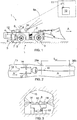
- FIG. 1 illustrates a mine vehicle 1, which in this case is a loading vehicle, whose front part is provided with a bucket for transporting and loading quarried material.
- the mine vehicle 1 may be a rock drilling rig or a transport vehicle provided with a platform, for instance.
- the mine vehicle 1 comprises a movable chassis 2, which is provided with several wheels 3, of which at least one is a drive wheel driven by an engine 4 through power transmission 5.
- the engine 4 may be an electric motor, a combustion engine, a hydraulic motor or any other device for providing a torque.
- the power transmission 5 typically comprises a gear system 6 and needed cardan shafts 7, differential gear and other power transmission members for transmitting the torque from the engine 4 to the drive wheels.
- the mine vehicle 1 is provided with a control system, which comprises at least a first control unit 8, which is arranged to control the actuators provided in the mine vehicle 1 for steering and operating it.
- the mine vehicle 1 may comprise a data transmission unit 9, by means of which the first control unit 8 may establish a data transmission connection 9a to a second control unit 10 external to the mine vehicle 1.
- the second control unit 10 may be located in a control room 11, which may be outside the mine.
- the control units 8 and 10 may be computers or similar devices.
- the control system of the mine vehicle 1 may include at least one gyroscope 12 for determining the direction of the vehicle accurately for positioning.
- the control system includes means for determining the distance travelled by the mine vehicle 1.
- Figure 4 illustrates a system suitable for distance measurement where the rotation of a wheel 3 is measured by one or more sensors 13. Based on the measurement data, the control system determines the rotation movement of the wheel and then calculates the length of the distance travelled by the vehicle.
- the control system may include one or more scanners 14, for example a laser scanner or a similar device for determining the space surrounding the mine vehicle 1 and its profiles. The positioning of the vehicle can be checked at certain intervals by comparing the environmental data scanned at the reference points and an environmental model of the stored route 16.
- Figures 2 and 3 illustrate the principle of scanning used in checking the positioning.
- One or both sides of the vehicle 1 may be provided with laser scanners 14 for determining the profile and topography of a mine tunnel 15.
- the route 16 of the mine vehicle 1 can be formed by teaching.
- the vehicle is driven by manual control along a desired route and simultaneously, the directions and distances of the route 16 are stored in the control system as an electronic map.
- the space surrounding the vehicle is also scanned during the teaching drive and the scanning result is stored in the control system as a three-dimensional environmental model showing the surface profile of the route travelled by the vehicle.
- the mine vehicle may be unmanned while the control system takes care of steering.
- the surroundings of the vehicle are scanned also during the automatic drive.
- the result from scanning is compared to the three dimensional environmental model stored in the control system, which enables positioning the real position of the mine vehicle in relation to the predetermined route of the vehicle. If, according to the comparison, the mine vehicle is not on the desired route, the control system forms correction values, by means of which the vehicle can be brought back to the correct route.
- Figure 4 illustrates a way of measuring the distance travelled by the mine vehicle 1.
- the engine drives one or more wheels 3 through power transmission 5.
- the information on the rotation movement of a vehicle wheel needed to determine the distance is obtained by means of one or more sensors 13.
- the sensor 13 may be arranged to directly monitor the wheel 3.
- the sensor 13 may be arranged to monitor the rotation movement of the wheel indirectly by monitoring the rotation movements of the power transmission 5 or engine 4.
- the rotation movement of the wheel 3 can be calculated in the control system when the transmission ratios are known.
- the control unit 8 can calculate the length of the distance travelled by the vehicle.
- the wheel 3 diameter D decreases due to wear, and thus there is a difference between the measured distance and the real distance travelled, which can be compensated for by taking a correction factor into account in the measurement result.
- the correction factor can be updated at certain intervals, for example each time a certain predetermined distance has been travelled. Thus the value of the correction factor follows the trend in the wear of the tyre.
- Figure 5 illustrates a working area defined for the control system as X and Y coordinates.
- the route to be driven is marked with reference number 16 and the driving direction of the mine vehicle at the moment to be examined with arrow A.
- the scanning results are compared with the environmental model in the control unit and the need for correcting positioning is determined.
- a correction in direction X is marked in the figure with reference symbol dx and a correction in direction Y with reference symbol dy.
- the magnitude of the correction need in driving direction A can be calculated using basic trigonometry. When the sum of correction needs formed during a certain distance is proportioned to the distance travelled, a correction factor is obtained for correcting the distance measurement to correspond to the changed wheel diameter.
- This arrangement also takes into consideration any surprising changes in the wheel, such as premature wear or detachment of the wear surface. In addition, it takes account of the fact how much the wheel has compressed, i.e. what is the effective wheel diameter. Thus the filling degree of an air filled wheel does not substantially affect the accuracy of the distance measurement.
- the mine may be provided with reference members at predetermined checkpoints for determining the real position of the vehicle.
- the reference members may be reflectors, for example, on which a laser beam provided in the vehicle is focused for determining the distance.
- the mine and/or the vehicle may be provided with radio, light or sound transmitters, which enable accurate determination of the position of the mine vehicle.
- the diameter of the new tyres is supplied to the control system of the mine vehicle.
- the tyre diameter can be fed manually into the control system or, alternatively, the diameter can be read automatically from identifiers provided in the tyres, for instance.
- the value of the correction factor can be set to correspond to the wheel.
- the value of the correction factor can be updated by determining, for example as shown in Figure 2 , an exact reference distance L ref for the mine, the length of this distance being known to the control system.
- a first reference point 30a and a second reference point 30b which may be laser transmitters, for example, may be arranged on the route of the mine vehicle 1.
- the sensor provided in the mine vehicle 1 is arranged to recognize the beam transmitted by the transmitters.
- the control system travels the reference distance L ref between the reference points 30a, 30b, it also measures this distance.
- the control system compares the measured distance to the reference distance.
- the value of the correction factor may be arranged to be updated by statistically determining an average wear rate for each tyre type. Since the normal wear of tyres follows a certain trend, it can be found out empirically how long a distance can be driven on average using a certain tyre type in certain circumstances until the tyre is worn out and has to be replaced. The diameter of a new tyre is known as well as that of a worn tyre. Based on this information, it can be determined relatively accurately how much the wheel diameter changes in relation to the distance travelled. The correction factor can then be updated linearly in relation to the distance driven. For noticing any surprising phenomena in the wheel, the wheel can be provided with a wear detector, for example, which gives an alarm if the wearing deviates from normal.
- the method according to the invention can be performed by executing a computer program in the processor of a computer belonging to the control system.
- the computer program implementing the method according to the invention can be stored in the memory of the control system, or the program can be loaded into the computer from a memory means, such as a CD-ROM.
- the computer program can be loaded from another computer via a data network to the computer belonging to the control system of the mine vehicle.
Landscapes
- Physics & Mathematics (AREA)
- Engineering & Computer Science (AREA)
- General Physics & Mathematics (AREA)
- Radar, Positioning & Navigation (AREA)
- Remote Sensing (AREA)
- Aviation & Aerospace Engineering (AREA)
- Automation & Control Theory (AREA)
- Optics & Photonics (AREA)
- Electromagnetism (AREA)
- Control Of Position, Course, Altitude, Or Attitude Of Moving Bodies (AREA)
Description
- The invention relates to a method of determining a distance travelled by a mine vehicle provided with positioning, the mine vehicle comprising: a chassis; several wheels; an engine; power transmission for transmitting a torque from the engine to at least one wheel; and a control system including at least a first control unit arranged in the vehicle; and means for determining the distance travelled; and the method comprising: monitoring rotation of at least one wheel and calculating the length of the distance travelled in the control system on the basis of the monitoring result and the diameter of the wheel monitored.
- The invention further relates to a control system of a mine vehicle, comprising at least: a first control unit, means for monitoring rotation of at least one wheel of the mine vehicle; the control system being arranged to determine a distance travelled by the vehicle on the basis of the rotation and diameter of the wheel.
- Unmanned mine vehicles can be guided in a mine along a desired route as long as the distance travelled by the vehicle and its driving direction can be determined. The vehicle direction can be found out with sufficient accuracy by means of a gyroscope, for example. The distance travelled can be calculated in the vehicle's control system after rotation data has first been measured directly from a vehicle wheel by suitable sensors, or indirectly from the power transmission or engine. The determination of the distance on the basis of the wheel rotation involves the problem that the diameter of tyres changes as they wear. Thus the real distance travelled by the vehicle and the distance determined by measuring may clearly differ from each other. Deviations in the distance determination decrease the location accuracy of the mine vehicle and make it more difficult for the vehicle to stay on the planned route. In documents
US-A-5890092 andDE-A-2 604 711 it is disclosed arrangements for monitoring a change in a wheel diameter. DocumentWO-A1-02/093282 EP-A1-1 357363 is a document in accordance with Article 54(3) EPC. - The object of the invention is to provide a novel and improved arrangement for locating a mine vehicle which automatically takes account of the wear of vehicle tyres in the distance measurement based on wheel rotation.
- The method according to the invention is characterized by the features presented in the characterized portion of the independent method claim.
- The control system according to the invention is characterized by the features presented in the characterized portion of the independent apparatus claim.
- The idea underlying the invention is that the control system of a mine vehicle automatically compensates for a deviation caused by the wear of tyres in the distance measurement. For compensation, the control system defines a correction factor, by which the result of the distance measurement is multiplied. The value of the correction factor is updated at predetermined intervals during the use of the mine vehicle. The value of the correction factor is updated according to the trend in the wear degree change of tyres.
- An advantage of the invention is that the control system automatically takes the wear of tyres into account in positioning, in which case the distance measurement and consequently the positioning accuracy of the vehicle are independent of the condition of the tyres. A further advantage is that the system requires no separate sensors and measuring means for determining the wheel diameter.
- The underlying idea of an embodiment according to the invention is that the compensation utilizes a positioning check performed at predetermined intervals, where the real position of the vehicle is determined first, the real position is compared to the route stored in the control system, and on the basis of these, the magnitude of the correction needed in the vehicle's travel direction is determined. The control system further includes a counter where the values obtained for the corrections in the travel direction can be added up. When the vehicle travels a predetermined distance, several correction values are added to the counter during this period. Based on the ratio between the magnitude of the correction value added to the counter and the distance travelled during the reference period, a correction factor is calculated, which can be updated to a new correction factor after the reference period for manipulating the result obtained from the distance measurement. A new correction factor is formed again during the next reference period.
- The idea underlying an embodiment of the invention is that a mine vehicle is taught a desired route by driving, which is stored in the control system as an electronic map. Profile information obtained from the route by scanners or corresponding measuring devices is also stored in the electronic route map. This way an environmental model of the route is formed where topographic information on the mine tunnel may be stored, for example. During the automatic drive of a mine vehicle, positioning is checked substantially continuously by scanning the surroundings of the vehicle and by comparing the environmental data obtained to the environmental model in the control system. On the basis of the differences between the measurement and the model, the real position of the vehicle can be found out and the correction need in the vehicle's driving direction determined at each moment the positioning is checked. The correction in the driving direction is used for forming a new correction factor.
- The idea underlying an embodiment of the invention is that the control system updates the value of the correction factor by taking into account only a predetermined portion of the new correction factor value determined on the basis of the positioning check when forming a new correction factor. The portion to be taken into account may be 0.1%, for instance. An advantage of this embodiment is that any inaccuracies in the measurement performed during a single reference period, such as wheel skidding, have no critical influence on the result. The arrangement reduces the effect of single deviations but takes the trend in the wear of the tyres into account.
- The idea underlying an embodiment of the invention is that at least two reference points, which the control system of the mine vehicle is arranged to recognize, have been determined for the mine in advance. The control system knows the exact distance between the reference points, i.e. the reference distance. When the vehicle travels along the route, the control system measures the distance between the reference points. The measurement result is compared to the reference distance to obtain a correction factor. The value of the correction factor can be updated each time the vehicle drives past the reference points.
- The idea underlying an embodiment of the invention is that the value of the correction factor is updated by taking into account the average wheel-specific reduction rate of the diameter determined statistically from the moment when the wheel was adopted to the removal moment of the wheel.
- The idea underlying an embodiment of the invention is that the mine vehicle is provided with a data transmission connection, by means of which a first control unit provided in the mine vehicle can communicate with a second control unit external to the vehicle. Mine vehicle of this kind may be unmanned.
- The invention will be described in greater detail in the accompanying drawings, in which
-
Figure 1 schematically illustrates a mine vehicle according to the invention, -
Figure 2 illustrates a schematic top view of an arrangement for ensuring positioning of a mine vehicle, -
Figure 3 schematically illustrates an arrangement for ensuring positioning of a mine vehicle seen in the longitudinal direction of the vehicle, -
Figure 4 schematically illustrates an arrangement according to the invention for measuring the distance travelled by the mine vehicle, and -
Figure 5 schematically illustrates a deviation of the mine vehicle from a planned route as X and Y coordinates of the control system and a correction in the driving direction determined by the control system so that the vehicle can resume the route. - For the sake of clarity, the figures show the invention in a simplified manner. Like reference numbers identify like elements.
-
Figure 1 illustrates amine vehicle 1, which in this case is a loading vehicle, whose front part is provided with a bucket for transporting and loading quarried material. Alternatively, themine vehicle 1 may be a rock drilling rig or a transport vehicle provided with a platform, for instance. Themine vehicle 1 comprises amovable chassis 2, which is provided withseveral wheels 3, of which at least one is a drive wheel driven by anengine 4 throughpower transmission 5. Theengine 4 may be an electric motor, a combustion engine, a hydraulic motor or any other device for providing a torque. Thepower transmission 5 typically comprises agear system 6 and neededcardan shafts 7, differential gear and other power transmission members for transmitting the torque from theengine 4 to the drive wheels. In addition, themine vehicle 1 is provided with a control system, which comprises at least afirst control unit 8, which is arranged to control the actuators provided in themine vehicle 1 for steering and operating it. Furthermore, themine vehicle 1 may comprise a data transmission unit 9, by means of which thefirst control unit 8 may establish adata transmission connection 9a to asecond control unit 10 external to themine vehicle 1. Thesecond control unit 10 may be located in acontrol room 11, which may be outside the mine. Thecontrol units mine vehicle 1 may include at least onegyroscope 12 for determining the direction of the vehicle accurately for positioning. Furthermore, the control system includes means for determining the distance travelled by themine vehicle 1.Figure 4 illustrates a system suitable for distance measurement where the rotation of awheel 3 is measured by one ormore sensors 13. Based on the measurement data, the control system determines the rotation movement of the wheel and then calculates the length of the distance travelled by the vehicle. In addition, the control system may include one ormore scanners 14, for example a laser scanner or a similar device for determining the space surrounding themine vehicle 1 and its profiles. The positioning of the vehicle can be checked at certain intervals by comparing the environmental data scanned at the reference points and an environmental model of the storedroute 16. -
Figures 2 and 3 illustrate the principle of scanning used in checking the positioning. One or both sides of thevehicle 1 may be provided withlaser scanners 14 for determining the profile and topography of amine tunnel 15. - The
route 16 of themine vehicle 1 can be formed by teaching. In that case, the vehicle is driven by manual control along a desired route and simultaneously, the directions and distances of theroute 16 are stored in the control system as an electronic map. The space surrounding the vehicle is also scanned during the teaching drive and the scanning result is stored in the control system as a three-dimensional environmental model showing the surface profile of the route travelled by the vehicle. During the production drive, the mine vehicle may be unmanned while the control system takes care of steering. The surroundings of the vehicle are scanned also during the automatic drive. The result from scanning is compared to the three dimensional environmental model stored in the control system, which enables positioning the real position of the mine vehicle in relation to the predetermined route of the vehicle. If, according to the comparison, the mine vehicle is not on the desired route, the control system forms correction values, by means of which the vehicle can be brought back to the correct route. -
Figure 4 illustrates a way of measuring the distance travelled by themine vehicle 1. The engine drives one ormore wheels 3 throughpower transmission 5. The information on the rotation movement of a vehicle wheel needed to determine the distance is obtained by means of one ormore sensors 13. Thesensor 13 may be arranged to directly monitor thewheel 3. Alternatively, thesensor 13 may be arranged to monitor the rotation movement of the wheel indirectly by monitoring the rotation movements of thepower transmission 5 orengine 4. The rotation movement of thewheel 3 can be calculated in the control system when the transmission ratios are known. On the basis of the rotation movement and diameter of thewheel 3, thecontrol unit 8 can calculate the length of the distance travelled by the vehicle. During the use, however, thewheel 3 diameter D decreases due to wear, and thus there is a difference between the measured distance and the real distance travelled, which can be compensated for by taking a correction factor into account in the measurement result. The correction factor can be updated at certain intervals, for example each time a certain predetermined distance has been travelled. Thus the value of the correction factor follows the trend in the wear of the tyre. -
Figure 5 illustrates a working area defined for the control system as X and Y coordinates. The route to be driven is marked withreference number 16 and the driving direction of the mine vehicle at the moment to be examined with arrow A. The scanning results are compared with the environmental model in the control unit and the need for correcting positioning is determined. A correction in direction X is marked in the figure with reference symbol dx and a correction in direction Y with reference symbol dy. Based on the correction needs in the X and Y directions, the magnitude of the correction need in driving direction A can be calculated using basic trigonometry. When the sum of correction needs formed during a certain distance is proportioned to the distance travelled, a correction factor is obtained for correcting the distance measurement to correspond to the changed wheel diameter. This arrangement also takes into consideration any surprising changes in the wheel, such as premature wear or detachment of the wear surface. In addition, it takes account of the fact how much the wheel has compressed, i.e. what is the effective wheel diameter. Thus the filling degree of an air filled wheel does not substantially affect the accuracy of the distance measurement. - It should be mentioned that instead of scanning, the positioning can be checked by another method. The mine may be provided with reference members at predetermined checkpoints for determining the real position of the vehicle. The reference members may be reflectors, for example, on which a laser beam provided in the vehicle is focused for determining the distance. Furthermore, the mine and/or the vehicle may be provided with radio, light or sound transmitters, which enable accurate determination of the position of the mine vehicle.
- When the tyres of the mine vehicle have worn out and they are replaced, the diameter of the new tyres is supplied to the control system of the mine vehicle. The tyre diameter can be fed manually into the control system or, alternatively, the diameter can be read automatically from identifiers provided in the tyres, for instance. At the same time, the value of the correction factor can be set to correspond to the wheel.
- Furthermore, the value of the correction factor can be updated by determining, for example as shown in
Figure 2 , an exact reference distance Lref for the mine, the length of this distance being known to the control system. For this purpose, afirst reference point 30a and asecond reference point 30b, which may be laser transmitters, for example, may be arranged on the route of themine vehicle 1. The sensor provided in themine vehicle 1 is arranged to recognize the beam transmitted by the transmitters. When the control system travels the reference distance Lref between thereference points - In addition, the value of the correction factor may be arranged to be updated by statistically determining an average wear rate for each tyre type. Since the normal wear of tyres follows a certain trend, it can be found out empirically how long a distance can be driven on average using a certain tyre type in certain circumstances until the tyre is worn out and has to be replaced. The diameter of a new tyre is known as well as that of a worn tyre. Based on this information, it can be determined relatively accurately how much the wheel diameter changes in relation to the distance travelled. The correction factor can then be updated linearly in relation to the distance driven. For noticing any surprising phenomena in the wheel, the wheel can be provided with a wear detector, for example, which gives an alarm if the wearing deviates from normal.
- The method according to the invention can be performed by executing a computer program in the processor of a computer belonging to the control system. The computer program implementing the method according to the invention can be stored in the memory of the control system, or the program can be loaded into the computer from a memory means, such as a CD-ROM. In addition, the computer program can be loaded from another computer via a data network to the computer belonging to the control system of the mine vehicle.
- The drawings and the related description are only intended to illustrate the inventive concept. The details of the invention may vary within the scope of the claims.
Claims (10)
- A method of determining a distance travelled by a mine vehicle provided with positioning,
the mine vehicle (1) comprising: a chassis (2); several wheels (3); an engine (4); power transmission (5) for transmitting a torque from the engine (4) to at least one wheel (3); and a control system including at least a first control unit (8) arranged in the vehicle (1); and means for determining the distance travelled; and the method comprising:
monitoring rotation of at least one wheel (3) and calculating the length of the distance travelled in the control system on the basis of the monitoring result and the diameter (D) of the wheel (3) monitored;
storing an environmental model of topographical surface profiles surrounding the planned route (16) in the control system;
monitoring environmental data on the profiles of the surfaces surrounding the vehicle during use;
performing a positioning check by comparing the monitored environmental data to the environmental model stored in the control system;
determining the real position of the vehicle (1) on the basis of the comparison and determining the deviation from the planned route (16);
characterized by
calculating a distance correction in the driving direction (A) of the vehicle (1);
determining a correction factor, based upon a trend in a change in the wheel (3) diameter (D);
correcting the value of the distance travelled obtained by calculating the value determined by the rotation of the wheels by means of the correction factor;
and updating the value of the correction factor at predetermined intervals by the result of the distance correction defined by comparison of the monitored environmental data to the environmental model. - A method according to claim 1, characterized by
performing a check on the vehicle (1) positioning at predetermined intervals, comprising determining the real position of the vehicle (1), and determining a deviation between the real position of the vehicle (1) and a planned route (16),
determining a correction in the driving direction (A) of the vehicle (1) corresponding to the deviation,
adding distance corrections in the driving direction (A) that have come up during a predetermined reference period to a counter in the control system, and
updating the correction factor on the basis of the ratio between the length of the distance measured during the reference period and the correction value added to the counter during the reference period. - A method according to claim 1 or 2, characterized by teaching the planned route (16) of the vehicle (1) to the control system in advance.
- A method according to claim 2 or 3, characterized by taking account of a predetermined portion of the update need produced by a single positioning check in the updating of the correction factor.
- A method according to any one of the preceding claims, characterized by transmitting data related to the control of the mine vehicle (1) between the first control unit (8) and a second control unit (10) external to the mine vehicle (1).
- A control system for a mine vehicle comprising at least:a first control unit (8),means for monitoring rotation of at least one wheel (3) of the mine vehicle (1),the control system being arranged to determine a distance travelled by the vehicle (1) on the basis of a monitoring result and diameter (D) of the wheel (3) monitored,an electronic environmental model of topographical surface profiles surrounding the planned route (16) is stored in the control system,the control system comprises means for forming electronic environmental data on the basis of the topographical surface profiles of space surrounding the mine vehicle (1), andthe control system is arranged to check positioning of the vehicle (1) by comparing the environmental data to the environmental model,characterized in thatthe control system is arranged to calculate a distance correction in the driving direction of the vehicle and to automatically correct the result from the distance measurement based on the wheel rotation by means of a correction factor, anda value of the correction factor is arranged to be updated at predetermined intervals by comparing the monitored environmental data to the environmental model, and thus a trend in a change of the wheel (3) diameter (D) is taken into account.
- A control system according to claim 6, characterized in that
the control system is arranged to check the positioning of the vehicle (1) at predetermined intervals and to determine a correction proposal for positioning in the driving direction (A) of the vehicle,
the control system includes a counter, which is arranged to add up the correction proposals during a predetermined reference period, and
the control arrangement is arranged to determine a correction factor value on the basis of the ratio between the length of the distance measured during the reference period and the correction value added to the counter during the reference period. - A control system according to claim 6 or 7, characterized in that the control system comprises at least one laser scanner (14) for checking the positioning of the vehicle (1).
- A control system according to any one of preceding claims 6 to 8, characterized in that the control system comprises a data transmission unit (9), by means of which a first control unit (8) is arranged to communicate with at least a second control unit (10) external to the mine vehicle (1).
- A mine vehicle comprising: a chassis (2); several wheels (3); an engine (4); power transmission (5) for transmitting a torque from the engine (4) to at least one wheel (3); and a control system, and wherein the control system is in accordance with claim 6.
Applications Claiming Priority (3)
| Application Number | Priority Date | Filing Date | Title |
|---|---|---|---|
| FI20030440A FI115161B (en) | 2003-03-25 | 2003-03-25 | Arrangement for the location of mining vehicles |
| FI20030440 | 2003-03-25 | ||
| PCT/FI2004/000172 WO2004085968A1 (en) | 2003-03-25 | 2004-03-25 | Method and control system for positioning a mine vehicle |
Publications (2)
| Publication Number | Publication Date |
|---|---|
| EP1606587A1 EP1606587A1 (en) | 2005-12-21 |
| EP1606587B1 true EP1606587B1 (en) | 2018-05-09 |
Family
ID=8565862
Family Applications (1)
| Application Number | Title | Priority Date | Filing Date |
|---|---|---|---|
| EP04723226.9A Expired - Lifetime EP1606587B1 (en) | 2003-03-25 | 2004-03-25 | Method and control system for positioning a mine vehicle |
Country Status (8)
| Country | Link |
|---|---|
| US (1) | US7643934B2 (en) |
| EP (1) | EP1606587B1 (en) |
| AU (2) | AU2004223687B2 (en) |
| CA (1) | CA2519323C (en) |
| CL (1) | CL2004000619A1 (en) |
| FI (1) | FI115161B (en) |
| WO (1) | WO2004085968A1 (en) |
| ZA (1) | ZA200507221B (en) |
Families Citing this family (17)
| Publication number | Priority date | Publication date | Assignee | Title |
|---|---|---|---|---|
| FI115414B (en) * | 2003-07-03 | 2005-04-29 | Sandvik Tamrock Oy | Arrangement for monitoring the location of the mining vehicle in the mine |
| CA2616613C (en) | 2005-07-26 | 2013-10-22 | Timothy D. Barfoot | Guidance, navigation, and control system for a vehicle |
| SE530113C2 (en) * | 2006-07-17 | 2008-03-04 | Atlas Copco Rock Drills Ab | Method for determining position of rock reinforcing bolt in tunnel or mine involves determining position of rock reinforcing bolt in tunnel or mine on basis of position of carrier and determined angle of rotation |
| FR2936324B1 (en) | 2008-09-19 | 2010-10-15 | Balyo Systems Sarl | NAVIGATION METHOD AND SYSTEM IMPLEMENTING SUCH A METHOD |
| US8428796B2 (en) * | 2008-10-17 | 2013-04-23 | Frank Wegner Donnelly | Rail conveyance system for mining |
| FI20095716A7 (en) * | 2009-06-24 | 2010-12-25 | Sandvik Mining & Construction Oy | Determining the data required for automatic control of a mobile mining machine |
| FI124169B (en) | 2011-06-14 | 2014-04-15 | Sandvik Mining & Constr Oy | Procedure for setting up a drilling plan |
| CN107255031B (en) | 2011-08-03 | 2019-10-25 | 久益环球地下采矿有限责任公司 | Stability systems for mining machines |
| SE537163C2 (en) | 2012-05-02 | 2015-02-24 | Atlas Copco Rock Drills Ab | Method and system for operating a mobile mining machine in a tunnel and a mobile mining machine |
| SE538027C2 (en) * | 2014-06-16 | 2016-02-16 | Atlas Copco Rock Drills Ab | Communication unit in at least partially remote controlled mining machine |
| CA2879241C (en) * | 2015-01-22 | 2017-08-29 | Yves Nelson | Drill positioning system for jumbo carrier unit |
| US10066346B2 (en) * | 2015-08-12 | 2018-09-04 | Topcon Positioning Systems, Inc. | Point cloud based surface construction |
| KR102136016B1 (en) * | 2016-01-04 | 2020-07-21 | 저장 리뱌오 로보츠 컴퍼니 리미티드 | Method and device for complementing robot wheel diameter |
| EP3660453B1 (en) * | 2018-11-30 | 2023-11-29 | Sandvik Mining and Construction Oy | Positioning of mobile object in underground worksite |
| KR20230120639A (en) | 2020-11-10 | 2023-08-17 | 다이노 노벨 아시아 퍼시픽 피티와이 리미티드 | System and Method for Determining Water Depth and Explosive Depth in Blast Holes |
| JP7650206B2 (en) | 2021-07-27 | 2025-03-24 | 株式会社ブリヂストン | TIRE MANAGEMENT DEVICE, PROGRAM, AND TIRE MANAGEMENT METHOD |
| CN116558503A (en) * | 2023-05-11 | 2023-08-08 | 蔚来汽车科技(安徽)有限公司 | Global positioning method for vehicle and vehicle |
Citations (3)
| Publication number | Priority date | Publication date | Assignee | Title |
|---|---|---|---|---|
| DE2604711A1 (en) * | 1976-02-06 | 1977-08-11 | Gebel Hans Peter Dr Ing | Mobile measurer for road information - has pressure sensor continuously measuring tyre press. w.r.t. wheel circumference during test run |
| US5890092A (en) * | 1994-09-01 | 1999-03-30 | Aisin Aw Co., Ltd. | Navigation system for vehicles including present position calculating means |
| WO2002093282A1 (en) * | 2001-05-14 | 2002-11-21 | Sandvik Tamrock Oy | Method and apparatus for determining position of mining machine |
Family Cites Families (12)
| Publication number | Priority date | Publication date | Assignee | Title |
|---|---|---|---|---|
| US3741473A (en) | 1971-12-08 | 1973-06-26 | C Finley | Odometer |
| US3735103A (en) | 1971-12-13 | 1973-05-22 | C Finley | Odometer |
| JPS5487580A (en) * | 1977-12-23 | 1979-07-12 | Nissan Motor | Trip meter |
| GB2117516A (en) | 1982-03-26 | 1983-10-12 | Rubery Owen Rockwell Ltd | Measuring distances travelled by non-powered wheeled vehicles |
| JP2689357B2 (en) | 1990-09-04 | 1997-12-10 | 株式会社ゼクセル | Relative direction detection method |
| SE469672B (en) | 1991-10-30 | 1993-08-16 | Elias Staicouras | Device for measuring exact speed and distance for a vehicle |
| IT1271241B (en) * | 1994-10-04 | 1997-05-27 | Consorzio Telerobot | NAVIGATION SYSTEM FOR AUTONOMOUS MOBILE ROBOT |
| JP3578511B2 (en) * | 1995-04-21 | 2004-10-20 | 株式会社ザナヴィ・インフォマティクス | Current position calculation device |
| DE69915156T2 (en) * | 1998-04-24 | 2004-10-28 | Inco Ltd., Toronto | Automatic guiding and measuring device |
| DE19945119C2 (en) | 1999-09-21 | 2001-12-06 | Mannesmann Vdo Ag | Method of navigating a ground vehicle |
| US6948576B2 (en) * | 2002-01-10 | 2005-09-27 | Jorge Angeles | Driving and transmission unit for use in rolling vehicles |
| JP4295953B2 (en) | 2002-04-26 | 2009-07-15 | パイオニア株式会社 | Distance coefficient learning device, method, program, recording medium for recording the program, movement status calculation device, and current position calculation device |
-
2003
- 2003-03-25 FI FI20030440A patent/FI115161B/en active IP Right Grant
-
2004
- 2004-03-24 CL CL200400619A patent/CL2004000619A1/en unknown
- 2004-03-25 EP EP04723226.9A patent/EP1606587B1/en not_active Expired - Lifetime
- 2004-03-25 US US10/550,606 patent/US7643934B2/en not_active Expired - Lifetime
- 2004-03-25 CA CA2519323A patent/CA2519323C/en not_active Expired - Lifetime
- 2004-03-25 AU AU2004223687A patent/AU2004223687B2/en not_active Expired
- 2004-03-25 WO PCT/FI2004/000172 patent/WO2004085968A1/en not_active Ceased
-
2005
- 2005-09-08 ZA ZA200507221A patent/ZA200507221B/en unknown
-
2009
- 2009-11-13 AU AU2009238278A patent/AU2009238278B2/en not_active Expired
Patent Citations (3)
| Publication number | Priority date | Publication date | Assignee | Title |
|---|---|---|---|---|
| DE2604711A1 (en) * | 1976-02-06 | 1977-08-11 | Gebel Hans Peter Dr Ing | Mobile measurer for road information - has pressure sensor continuously measuring tyre press. w.r.t. wheel circumference during test run |
| US5890092A (en) * | 1994-09-01 | 1999-03-30 | Aisin Aw Co., Ltd. | Navigation system for vehicles including present position calculating means |
| WO2002093282A1 (en) * | 2001-05-14 | 2002-11-21 | Sandvik Tamrock Oy | Method and apparatus for determining position of mining machine |
Also Published As
| Publication number | Publication date |
|---|---|
| CA2519323C (en) | 2012-09-04 |
| AU2009238278A1 (en) | 2009-12-03 |
| US7643934B2 (en) | 2010-01-05 |
| FI20030440L (en) | 2004-09-26 |
| AU2004223687A1 (en) | 2004-10-07 |
| US20060235609A1 (en) | 2006-10-19 |
| CL2004000619A1 (en) | 2005-02-04 |
| FI115161B (en) | 2005-03-15 |
| AU2004223687B2 (en) | 2009-08-13 |
| FI20030440A0 (en) | 2003-03-25 |
| EP1606587A1 (en) | 2005-12-21 |
| AU2009238278B2 (en) | 2011-03-17 |
| WO2004085968A1 (en) | 2004-10-07 |
| CA2519323A1 (en) | 2004-10-07 |
| ZA200507221B (en) | 2006-06-28 |
Similar Documents
| Publication | Publication Date | Title |
|---|---|---|
| AU2009238278B2 (en) | Method and control system for positioning a mine vehicle | |
| US9008886B2 (en) | Method of modifying a worksite | |
| CA2765142C (en) | Determination of routes for arranging automatic control of mobile mining machine | |
| US8606495B2 (en) | Method and apparatus for mining vehicle safety arrangements | |
| US9182760B2 (en) | Method of managing a worksite | |
| CN203546576U (en) | Building machinery | |
| AU2010264551B2 (en) | Determination of route for arranging automatic control of mobile mining machine | |
| US20170269591A1 (en) | Travel control device for work vehicle, and work vehicle | |
| US8924143B2 (en) | Method and apparatus for arranging mining vehicle positioning | |
| US11150645B2 (en) | Localization system for underground mining applications | |
| JP6990600B2 (en) | Autonomous driving system | |
| US20180209120A1 (en) | Surveying system and method using mobile work machine | |
| US20150198736A1 (en) | Terrain mapping system using virtual tracking features | |
| ZA200600845B (en) | Method and system for monitoring location of mining vehicle | |
| RU2572434C1 (en) | Earthmover working tool control system | |
| ES2167284T3 (en) | PROCEDURE OF REALIZATION THAT USES A GLOBAL POSITIONING SYSTEM. | |
| US11397416B2 (en) | Intelligent motion control through surface scan comparison and feature recognition | |
| JPH04164210A (en) | Height measuring device for moving body | |
| CN114662259A (en) | Coal mining machine three-dimensional positioning method and system based on high-precision inertial navigation |
Legal Events
| Date | Code | Title | Description |
|---|---|---|---|
| PUAI | Public reference made under article 153(3) epc to a published international application that has entered the european phase |
Free format text: ORIGINAL CODE: 0009012 |
|
| 17P | Request for examination filed |
Effective date: 20050928 |
|
| AK | Designated contracting states |
Kind code of ref document: A1 Designated state(s): AT BE BG CH CY CZ DE DK EE ES FI FR GB GR HU IE IT LI LU MC NL PL PT RO SE SI SK TR |
|
| AX | Request for extension of the european patent |
Extension state: AL LT LV MK |
|
| DAX | Request for extension of the european patent (deleted) | ||
| 17Q | First examination report despatched |
Effective date: 20090326 |
|
| GRAP | Despatch of communication of intention to grant a patent |
Free format text: ORIGINAL CODE: EPIDOSNIGR1 |
|
| STAA | Information on the status of an ep patent application or granted ep patent |
Free format text: STATUS: GRANT OF PATENT IS INTENDED |
|
| INTG | Intention to grant announced |
Effective date: 20170724 |
|
| GRAJ | Information related to disapproval of communication of intention to grant by the applicant or resumption of examination proceedings by the epo deleted |
Free format text: ORIGINAL CODE: EPIDOSDIGR1 |
|
| STAA | Information on the status of an ep patent application or granted ep patent |
Free format text: STATUS: EXAMINATION IS IN PROGRESS |
|
| RAP1 | Party data changed (applicant data changed or rights of an application transferred) |
Owner name: SANDVIK MINING AND CONSTRUCTION OY |
|
| GRAP | Despatch of communication of intention to grant a patent |
Free format text: ORIGINAL CODE: EPIDOSNIGR1 |
|
| STAA | Information on the status of an ep patent application or granted ep patent |
Free format text: STATUS: GRANT OF PATENT IS INTENDED |
|
| INTC | Intention to grant announced (deleted) | ||
| INTG | Intention to grant announced |
Effective date: 20171220 |
|
| GRAS | Grant fee paid |
Free format text: ORIGINAL CODE: EPIDOSNIGR3 |
|
| GRAA | (expected) grant |
Free format text: ORIGINAL CODE: 0009210 |
|
| STAA | Information on the status of an ep patent application or granted ep patent |
Free format text: STATUS: THE PATENT HAS BEEN GRANTED |
|
| AK | Designated contracting states |
Kind code of ref document: B1 Designated state(s): AT BE BG CH CY CZ DE DK EE ES FI FR GB GR HU IE IT LI LU MC NL PL PT RO SE SI SK TR |
|
| REG | Reference to a national code |
Ref country code: GB Ref legal event code: FG4D |
|
| REG | Reference to a national code |
Ref country code: CH Ref legal event code: EP Ref country code: AT Ref legal event code: REF Ref document number: 997991 Country of ref document: AT Kind code of ref document: T Effective date: 20180515 |
|
| REG | Reference to a national code |
Ref country code: DE Ref legal event code: R096 Ref document number: 602004052689 Country of ref document: DE Ref country code: IE Ref legal event code: FG4D |
|
| REG | Reference to a national code |
Ref country code: DE Ref legal event code: R096 Ref document number: 602004052689 Country of ref document: DE |
|
| REG | Reference to a national code |
Ref country code: SE Ref legal event code: TRGR |
|
| REG | Reference to a national code |
Ref country code: NL Ref legal event code: MP Effective date: 20180509 |
|
| PG25 | Lapsed in a contracting state [announced via postgrant information from national office to epo] |
Ref country code: ES Free format text: LAPSE BECAUSE OF FAILURE TO SUBMIT A TRANSLATION OF THE DESCRIPTION OR TO PAY THE FEE WITHIN THE PRESCRIBED TIME-LIMIT Effective date: 20180509 |
|
| PG25 | Lapsed in a contracting state [announced via postgrant information from national office to epo] |
Ref country code: NL Free format text: LAPSE BECAUSE OF FAILURE TO SUBMIT A TRANSLATION OF THE DESCRIPTION OR TO PAY THE FEE WITHIN THE PRESCRIBED TIME-LIMIT Effective date: 20180509 Ref country code: GR Free format text: LAPSE BECAUSE OF FAILURE TO SUBMIT A TRANSLATION OF THE DESCRIPTION OR TO PAY THE FEE WITHIN THE PRESCRIBED TIME-LIMIT Effective date: 20180810 |
|
| REG | Reference to a national code |
Ref country code: AT Ref legal event code: MK05 Ref document number: 997991 Country of ref document: AT Kind code of ref document: T Effective date: 20180509 |
|
| PG25 | Lapsed in a contracting state [announced via postgrant information from national office to epo] |
Ref country code: RO Free format text: LAPSE BECAUSE OF FAILURE TO SUBMIT A TRANSLATION OF THE DESCRIPTION OR TO PAY THE FEE WITHIN THE PRESCRIBED TIME-LIMIT Effective date: 20180509 Ref country code: CZ Free format text: LAPSE BECAUSE OF FAILURE TO SUBMIT A TRANSLATION OF THE DESCRIPTION OR TO PAY THE FEE WITHIN THE PRESCRIBED TIME-LIMIT Effective date: 20180509 Ref country code: EE Free format text: LAPSE BECAUSE OF FAILURE TO SUBMIT A TRANSLATION OF THE DESCRIPTION OR TO PAY THE FEE WITHIN THE PRESCRIBED TIME-LIMIT Effective date: 20180509 Ref country code: PL Free format text: LAPSE BECAUSE OF FAILURE TO SUBMIT A TRANSLATION OF THE DESCRIPTION OR TO PAY THE FEE WITHIN THE PRESCRIBED TIME-LIMIT Effective date: 20180509 Ref country code: AT Free format text: LAPSE BECAUSE OF FAILURE TO SUBMIT A TRANSLATION OF THE DESCRIPTION OR TO PAY THE FEE WITHIN THE PRESCRIBED TIME-LIMIT Effective date: 20180509 Ref country code: SK Free format text: LAPSE BECAUSE OF FAILURE TO SUBMIT A TRANSLATION OF THE DESCRIPTION OR TO PAY THE FEE WITHIN THE PRESCRIBED TIME-LIMIT Effective date: 20180509 Ref country code: DK Free format text: LAPSE BECAUSE OF FAILURE TO SUBMIT A TRANSLATION OF THE DESCRIPTION OR TO PAY THE FEE WITHIN THE PRESCRIBED TIME-LIMIT Effective date: 20180509 |
|
| REG | Reference to a national code |
Ref country code: CH Ref legal event code: PK Free format text: BERICHTIGUNGEN |
|
| REG | Reference to a national code |
Ref country code: DE Ref legal event code: R097 Ref document number: 602004052689 Country of ref document: DE |
|
| RIC2 | Information provided on ipc code assigned after grant |
Ipc: G05D 1/02 20060101ALI20041011BHEP Ipc: G01C 22/00 20060101AFI20041011BHEP |
|
| PG25 | Lapsed in a contracting state [announced via postgrant information from national office to epo] |
Ref country code: IT Free format text: LAPSE BECAUSE OF FAILURE TO SUBMIT A TRANSLATION OF THE DESCRIPTION OR TO PAY THE FEE WITHIN THE PRESCRIBED TIME-LIMIT Effective date: 20180509 |
|
| PLBE | No opposition filed within time limit |
Free format text: ORIGINAL CODE: 0009261 |
|
| STAA | Information on the status of an ep patent application or granted ep patent |
Free format text: STATUS: NO OPPOSITION FILED WITHIN TIME LIMIT |
|
| 26N | No opposition filed |
Effective date: 20190212 |
|
| PG25 | Lapsed in a contracting state [announced via postgrant information from national office to epo] |
Ref country code: SI Free format text: LAPSE BECAUSE OF FAILURE TO SUBMIT A TRANSLATION OF THE DESCRIPTION OR TO PAY THE FEE WITHIN THE PRESCRIBED TIME-LIMIT Effective date: 20180509 |
|
| PG25 | Lapsed in a contracting state [announced via postgrant information from national office to epo] |
Ref country code: MC Free format text: LAPSE BECAUSE OF FAILURE TO SUBMIT A TRANSLATION OF THE DESCRIPTION OR TO PAY THE FEE WITHIN THE PRESCRIBED TIME-LIMIT Effective date: 20180509 |
|
| REG | Reference to a national code |
Ref country code: CH Ref legal event code: PL |
|
| GBPC | Gb: european patent ceased through non-payment of renewal fee |
Effective date: 20190325 |
|
| PG25 | Lapsed in a contracting state [announced via postgrant information from national office to epo] |
Ref country code: LU Free format text: LAPSE BECAUSE OF NON-PAYMENT OF DUE FEES Effective date: 20190325 |
|
| REG | Reference to a national code |
Ref country code: BE Ref legal event code: MM Effective date: 20190331 |
|
| PG25 | Lapsed in a contracting state [announced via postgrant information from national office to epo] |
Ref country code: CH Free format text: LAPSE BECAUSE OF NON-PAYMENT OF DUE FEES Effective date: 20190331 Ref country code: LI Free format text: LAPSE BECAUSE OF NON-PAYMENT OF DUE FEES Effective date: 20190331 Ref country code: GB Free format text: LAPSE BECAUSE OF NON-PAYMENT OF DUE FEES Effective date: 20190325 |
|
| PG25 | Lapsed in a contracting state [announced via postgrant information from national office to epo] |
Ref country code: BE Free format text: LAPSE BECAUSE OF NON-PAYMENT OF DUE FEES Effective date: 20190331 Ref country code: FR Free format text: LAPSE BECAUSE OF NON-PAYMENT OF DUE FEES Effective date: 20190331 |
|
| PG25 | Lapsed in a contracting state [announced via postgrant information from national office to epo] |
Ref country code: TR Free format text: LAPSE BECAUSE OF FAILURE TO SUBMIT A TRANSLATION OF THE DESCRIPTION OR TO PAY THE FEE WITHIN THE PRESCRIBED TIME-LIMIT Effective date: 20180509 |
|
| PG25 | Lapsed in a contracting state [announced via postgrant information from national office to epo] |
Ref country code: PT Free format text: LAPSE BECAUSE OF FAILURE TO SUBMIT A TRANSLATION OF THE DESCRIPTION OR TO PAY THE FEE WITHIN THE PRESCRIBED TIME-LIMIT Effective date: 20180910 |
|
| PG25 | Lapsed in a contracting state [announced via postgrant information from national office to epo] |
Ref country code: CY Free format text: LAPSE BECAUSE OF FAILURE TO SUBMIT A TRANSLATION OF THE DESCRIPTION OR TO PAY THE FEE WITHIN THE PRESCRIBED TIME-LIMIT Effective date: 20180509 |
|
| PG25 | Lapsed in a contracting state [announced via postgrant information from national office to epo] |
Ref country code: HU Free format text: LAPSE BECAUSE OF FAILURE TO SUBMIT A TRANSLATION OF THE DESCRIPTION OR TO PAY THE FEE WITHIN THE PRESCRIBED TIME-LIMIT; INVALID AB INITIO Effective date: 20040325 |
|
| PGFP | Annual fee paid to national office [announced via postgrant information from national office to epo] |
Ref country code: IE Payment date: 20230209 Year of fee payment: 20 Ref country code: FI Payment date: 20230315 Year of fee payment: 20 Ref country code: BG Payment date: 20230215 Year of fee payment: 20 |
|
| PGFP | Annual fee paid to national office [announced via postgrant information from national office to epo] |
Ref country code: SE Payment date: 20230210 Year of fee payment: 20 Ref country code: DE Payment date: 20230131 Year of fee payment: 20 |
|
| P01 | Opt-out of the competence of the unified patent court (upc) registered |
Effective date: 20230603 |
|
| REG | Reference to a national code |
Ref country code: DE Ref legal event code: R071 Ref document number: 602004052689 Country of ref document: DE |
|
| REG | Reference to a national code |
Ref country code: IE Ref legal event code: MK9A |
|
| REG | Reference to a national code |
Ref country code: SE Ref legal event code: EUG |
|
| PG25 | Lapsed in a contracting state [announced via postgrant information from national office to epo] |
Ref country code: IE Free format text: LAPSE BECAUSE OF EXPIRATION OF PROTECTION Effective date: 20240325 |
|
| PG25 | Lapsed in a contracting state [announced via postgrant information from national office to epo] |
Ref country code: IE Free format text: LAPSE BECAUSE OF EXPIRATION OF PROTECTION Effective date: 20240325 |