EP1605545A1 - Earphone antenna and portable radio equipment provided with earphone antenna - Google Patents
Earphone antenna and portable radio equipment provided with earphone antenna Download PDFInfo
- Publication number
- EP1605545A1 EP1605545A1 EP05012038A EP05012038A EP1605545A1 EP 1605545 A1 EP1605545 A1 EP 1605545A1 EP 05012038 A EP05012038 A EP 05012038A EP 05012038 A EP05012038 A EP 05012038A EP 1605545 A1 EP1605545 A1 EP 1605545A1
- Authority
- EP
- European Patent Office
- Prior art keywords
- earphone
- signal
- cable
- audio signal
- shield
- Prior art date
- Legal status (The legal status is an assumption and is not a legal conclusion. Google has not performed a legal analysis and makes no representation as to the accuracy of the status listed.)
- Granted
Links
Images


Classifications
-
- H—ELECTRICITY
- H01—ELECTRIC ELEMENTS
- H01Q—ANTENNAS, i.e. RADIO AERIALS
- H01Q1/00—Details of, or arrangements associated with, antennas
- H01Q1/44—Details of, or arrangements associated with, antennas using equipment having another main function to serve additionally as an antenna, e.g. means for giving an antenna an aesthetic aspect
- H01Q1/46—Electric supply lines or communication lines
-
- H—ELECTRICITY
- H04—ELECTRIC COMMUNICATION TECHNIQUE
- H04B—TRANSMISSION
- H04B1/00—Details of transmission systems, not covered by a single one of groups H04B3/00 - H04B13/00; Details of transmission systems not characterised by the medium used for transmission
- H04B1/38—Transceivers, i.e. devices in which transmitter and receiver form a structural unit and in which at least one part is used for functions of transmitting and receiving
-
- H—ELECTRICITY
- H01—ELECTRIC ELEMENTS
- H01Q—ANTENNAS, i.e. RADIO AERIALS
- H01Q1/00—Details of, or arrangements associated with, antennas
- H01Q1/27—Adaptation for use in or on movable bodies
- H01Q1/273—Adaptation for carrying or wearing by persons or animals
-
- H—ELECTRICITY
- H01—ELECTRIC ELEMENTS
- H01Q—ANTENNAS, i.e. RADIO AERIALS
- H01Q9/00—Electrically-short antennas having dimensions not more than twice the operating wavelength and consisting of conductive active radiating elements
- H01Q9/04—Resonant antennas
- H01Q9/16—Resonant antennas with feed intermediate between the extremities of the antenna, e.g. centre-fed dipole
-
- H—ELECTRICITY
- H04—ELECTRIC COMMUNICATION TECHNIQUE
- H04R—LOUDSPEAKERS, MICROPHONES, GRAMOPHONE PICK-UPS OR LIKE ACOUSTIC ELECTROMECHANICAL TRANSDUCERS; ELECTRIC HEARING AIDS; PUBLIC ADDRESS SYSTEMS
- H04R1/00—Details of transducers, loudspeakers or microphones
- H04R1/10—Earpieces; Attachments therefor ; Earphones; Monophonic headphones
Definitions
- the present invention contains subject mater related to Japanese Patent Application No. JP2004-167551 filed in the Japanese Patent Office on June 4, 2004, the entire contents of which being incorporated herein by reference.
- the present invention relates to an earphone antenna for portable radio equipment put on a human body at use, and portable radio equipment provided with this earphone antenna.
- a rod antenna and an earphone antenna which utilizes a signal wire for transmitting audio signal to earphones is used as an antenna.
- a earphone antenna is disclosed in Japanese Patent Application Publication No. 2003-163529
- the earphone antenna which utilizes the signal wire for transmitting audio signal to earphones as an antenna had such a problem that because the earphone and the signal wire make direct contact with the human body, it allowed the human body to cause a significant influence on radio equipment via the antenna and deteriorate stability of reception substantially.
- VHF bands from 90 to 108 MHz (1-3 channels) and from 170 to 222 MHz (4-12 channels), as well as UHF band from 470 to 770 MHz (13-62 channels) are used, therefore, an LCD television receiver for receiving the television broadcasts is required to receive high frequency signals in an extremely wide band range from 90 to 770 MHz, thereby with a conventional rod antenna or earphone antenna the performance of which is inferior to a fixed-type antenna, there was a problem that it was extremely difficult to secure a sufficient sensitivity in the frequency band range required.
- the rod antenna and the earphone antenna is a monopole antenna which resonates at ⁇ /4, its reception sensitivity is greatly influenced by a ground size of a portable radio terminal, thereby limiting the design of the portable radio equipment.
- the present invention is contemplated to solve the aforementioned problems associated with the conventional art, and it is desirable to provide an earphone antenna which is capable of reducing the influence of the human body to achieve a high gain in a wide band range, and also provide portable radio equipment which secures reception stability.
- An earphone antenna includes: an earphone cable having a pair of first signal lines which are insulation-coated for supplying audio signal to an earphone; a shield cable including a coaxial cable having a central conductor for passing high frequency signal, which is coated with an insulator and further covered with a first shield wire, a second signal line for audio signal which is insulation-coated, and an insulation-coated grounding wire, the external all of them being covered with a second shield wire via an insulation material, with one end of the shield cable being connected to a main body of radio equipment via a multipin connector; and a connection block which connects the other end of the shield cable to the earphone cable described above; wherein in the aforementioned connection block, an audio signal transmission path is formed by connecting the first shield wire of the coaxial cable to a ground, connecting the central conductor of the coaxial cable to one of the pair of first signal lines of the earphone cable, as well as to the other one of the pair of first signal lines of the earphone cable
- portable radio equipment includes: a main body of radio equipment provided with a multipin jack which is connected to a tuner and an audio signal output unit; and an earphone antenna which includes: an earphone cable having a pair of first signal lines which are insulation-coated for supplying audio signal to an earphone; a shield cable including a coaxial cable having a central conductor for passing high frequency signal, which is coated with an insulator and further covered with a first shield wire, a second signal line for audio signal which is insulation-coated, and an insulation-coated grounding wire, the external all of them being covered with a second shield wire via an insulation material, with one end of the shield cable being connected to a main body of radio equipment via a multipin connector; and a connection block which connects the other end of the shield cable to the earphone cable described above; wherein in the aforementioned connection block, an audio signal transmission path is formed by connecting the first shield wire of the coaxial cable to a ground, connecting the central conductor of the
- the transmission path for audio signals is formed by connecting the first shield wire of the coaxial cable to the ground in the connection block described above, connecting the central conductor of the coaxial cable to one of the first signal lines of the earphone cables, and connecting to the other one of the first signal lines of the earphone cables via a capacitor which becomes high impedance in the frequency range of audio signal and low impedance in the frequency range of high frequency signal, then by connecting the second signal lines for audio signal and ground wiring respectively to the first signal lines of the two earphone cables via a high frequency choke which becomes low impedance in the frequency range of audio signal and high impedance in the frequency range of high frequency signal, and wherein because the sleeve antenna composed of the earphone cables described above and the shield wire which covers the external of the coaxial cable, the second signal lines for audio signal and the ground wiring is provided by connecting the aforementioned ground to the second shield wire which covers the external of the coaxial cable, the second signal lines for audio signal and the ground
- An earphone antenna according to an embodiment of the present invention may be provided with, for example, stereophonic earphones which are connected to the aforementioned connection block via a pair of earphone cables, and a high frequency choke inserted in a portion en route to one or both of the earphone cables to alter a resonance frequency between the earphone cables or make it variable.
- the earphone antenna may be provided with a microphone and a switch for switching mounted in the aforementioned connection block.
- the earphone antenna according to an embodiment of the present invention may be provided with an amplifier mounted in the aforementioned connection block.
- a transmission path for audio signal is formed by connecting the first shield wire of the coaxial cable to the ground, connecting the central conductor of the coaxial cable to one of the first signal lines of the earphone cable and to the other one of the first signal lines of the earphone cables via a capacitor which becomes high impedance in the frequency band of audio signal and low impedance in the frequency range of high frequency signal, as well as by connecting the second signal line for audio signal and the grounding wire respectively to the pair of first signal lines of the earphone cable via the high frequency choke which becomes low impedance in the frequency range of audio signal and high impedance in the frequency range of high frequency signal, and wherein an earphone antenna, which is a sleeve antenna composed of the earphone cable and the shield wire which covers the external of the coaxial cable, the second signal line and the grounding wire, is formed by connecting the ground to the second shield wire which covers the external of the coaxial cable, the second signal lines for audio signal
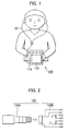
- the present invention is applicable to, for example, an LCD television receiver 100 shown in FIG. 1.
- an earphone antenna 10 is connected to a main body of the receiver 120 via a pin jack connector 110.
- the pin jack connector 110 is composed respectively of a five-electrode pin 110A and a jack 110B, to which five kinds of lines, i.e., antenna 7, headphone detection 1, audio L channel 2, audio R channel 5, and ground 6 are connected.
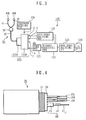
- a tuner unit 121 In a main body of the receiver 120, as shown in FIG. 3, there are provided a tuner unit 121, an IF signal processing unit 122 connected to the tuner 121, a video signal processing unit 123, an audio signal processing unit 125 both connected to the IF signal processing unit 122, a liquid crystal display unit 124 connected to the video signal processing unit 123, and a jack 110B which constitutes the pin jack connector 110 described above.
- the jack 110B described above has five movable terminals 1, 2, 5, 6, 7 and two fixed terminals 3, 4 as shown in FIG. 2, wherein, as shown in FIG. 3, the movable terminal 7 is connected to the tuner unit 121 as an antenna terminal 7, and the movable terminals 2, 5 are connected to the audio signal processing unit 125 as audio L channel terminal 2 and audio R channel terminal 5. And the headphone detection terminal 1 is connected to a headphone detection unit 126.
- Movable terminal 6 is connected to GND of a substrate in the main body of the radio equipment as a common ground terminal (Gnd) of the radio equipment.
- Fixed terminals 3, 4 are terminals for firmly holding the pins.
- An earphone antenna 10 is comprised of a shield cable 20 one end of which is connected to the main body of the receiver 120 via the five pin jack connector 110 described above, a connection block 30 which is connected to the other end of the shield cable 20, and stereophonic earphones 40L, 40R which are connected to this connection block 30 via two earphone cables 41, 42.
- the shield cable 20 is comprised of a coaxial cable 24 which has a central conductor 21 for transmitting a high frequency signal, which is coated with an insulator 22 and further covered with a shield wire 23; signal lines 25L, 25R for audio signal which are insulation-coated; and a signal line for headphone detection 25C, wherein the external all of them are covered with a shield wire 27 which is formed by winding soft copper or with a braided structure via an insulation sheet 26 made of paper or vinyl sheet.
- this shield cable 20 there is provided the five-pin connector 110A as connected to the central conductor 21 of the coaxial cable 24 and the shield wire 23 thereof, signal lines 25L, 25R for audio signal, and the headphone detection signal wire 25C. Further, at the other end of this shield cable 20, there is provided the connection block 30 as connected to the central conductor 21, the shield wire 23 thereof, the signal lines 25R, 25R for audio signals, the headphone detection signal line 25C, and to the shield wire 27.
- shield wire 27 which covers the coaxial cable 24, audio signal lines 25L, 25R and the headphone detection signal line 25C is connected to the aforementioned connection block 30, but is not connected to the aforementioned pin 110A.
- the shield wire 23 of the coaxial cable 24 is used as a common grounding wire for the central conductor 21 and the signal lines 25L, 25R for audio signal, it is not limited thereto, and a grounding wire for the signal lines 25L, 25R for audio signal may be provided in addition.
- a LCD television receiver 100 which is not provided with a headphone detection unit 126, it may be configured such that the headphone detection signal line 25C is used as a grounding wire for the signal lines 25L, 25R for audio signal.
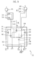
- connection block 30 has a substrate 34 on which there are formed a ground pattern 31 in the center thereof, transmission line patterns 32L, 32R for stereophonic audio signals mounted on both sides of the ground pattern 31, three connection lands 33L, 33R, 33C mounted at leading edge portions of the ground pattern 31, and a connection land 33D mounted on one side of the ground pattern 31.
- high frequency chokes 35L, 35R for connecting therethrough the end portions of the transmission line patterns 32L, 32R for the stereophonic audio signals to the first and the second connection lands 33L, 33R among the aforementioned three connection lands 33L, 33R, 33C; a high frequency choke 35C for connecting therethrough the ground pattern 31 to the third connection land 33C among the three connection lands 33L, 33R, 33C; a chip capacitor 36L for connecting therethrough the first connection land 33L and the third connection land 33C; a chip capacitor 36R for connecting therethrough the second connection land 33R and the third connection land 33C; and a chip capacitor 36 for connecting therethrough the third connection land 33C and a fourth connection land 33D.
- a left-side earphone cable 41 including two signal lines 41A, 41B for supplying left channel audio signal to a left-side earphone 40L is connected to the first connection land 33L and the third connection land 33C
- a right-side earphone cable 42 including two signal lines 42A, 42B for supplying right channel audio signal to a right-side earphone 40R is connected to the second connection land 33R and the third connection land 33C.
- connection block 30 the aforementioned shield cable 20 is connected in such a manner as will be described in the following.
- the left side audio signal line 25L and the right side signal line 25R of the shield cable 20 are connected to the transmission line patterns 32L and 32R for audio signal formed on the substrate 34, and further the headphone detection signal line 25C thereof is connected to the ground pattern 31. Further, on the ground pattern 31, the central conductor 21 and the shield wire 23 which make up the axial structure in the shield cable 20 are laid out, and the shield wire 23 is connected to the ground pattern 31, while an end of the central conductor 21 is connected to the fourth connection land 33D.
- the shield wire 27 is directly connected to GND 31.
- the chip capacitor 36 for connecting between the third connection land 33C and the fourth connection land 33D therethrough can be substituted with a capacitor for breakdown prevention, which is not shown, to be inserted between the movable terminal 7 and the tuner unit 121.
- the end of the central conductor 21 constituting the coaxial structure in the shield cable 20 is directly connected to the third connection land 33C.
- the aforementioned high frequency choke 35L, 35R, 35C there are used ferrite beads, for example, BLM18HD102SN1, size 1608 produced by Murata Manufacturing Ltd.
- the high frequency chokes 35L, 35R, 35C which use this ferrite beads, become low impedance to audio signals in a frequency band below 20 kHz, and high impedance to high frequency signals, thereby preventing passage of the high frequency signal.
- chip capacitors 36L, 36R, 36C such ones having capacitance of 10 pF are used respectively, which become high impedance to audio signals in the frequency band below 20 kHz blocking passage of the audio signal, and become low impedance to the high frequency signal.
- This earphone antenna 10 as indicated in a schematic electrical circuitry diagram shown in FIG. 6, has earphone cables 41, 42 led out from both sides, each including two signal lines 41A, 41B/42A, 42B of the left/right side signal lines and GND, for transmitting audio signals to speakers 40L, 40R of stereophonic earphones, then in order to separate the audio signal and the high frequency signal, it is configured such that high frequency wave chokes 35L, 35R, 35C using the ferrite beads are provided at input portions of the audio signal and at a portion falling to the ground, i.e., at portions of the connection lands 33L, 33R, 33C, which become high impedance (1 k ⁇ or greater) in the frequency band for use in television broadcasts, and low impedance in the audio frequency band (less than 20 kHz), thereby separating the audio signal and the high frequency signal.
- high frequency wave chokes 35L, 35R, 35C using the ferrite beads are provided at input portions of the audio signal and at a portion falling
- the earphone cables 41, 42 including two signal lines 41A, 41B/42A, 42B on each side, is connected to the central conductor 21 which is a signal line of the coaxial cable 23 associated with high frequency, therefore, in order to be separated therefrom regarding the audio range, it is configured to connect between the connection lands 33L or 33R and 33C via chip capacitors 36L, 36R of 10 pF, so as to separate the signals in the audio band range, and connect in RF signals (frequency range of television bands).
- the frequency bands allocated for use to television broadcasts in Japan are, 90M to 108MHz (1-3 channels) and 170M to 222MHz (4-12 channels) in VHF, and 470M to 770MHz (13-62 channels) in UHF band.
- this earphone antenna 10 by configuring such that the shield wire 27 which covers the coaxial cable 24 and the signal lines 25L, 25R for audio signals is directly connected to GND 31, a sleeve antenna structure is provided to use the earphone cables 41, 42 and the shield wire 27 as an aerial which resonates over its line length, wherein respective lengths thereof are adjusted so as to be able to receive 100MHz in the VHF band.
- a characteristic impedance of the coaxial cable 24 is set at 75 ⁇ , a length of the shield cable 20 at 70 cm, lengths of the earphone cables 41, 42 at 50cm, and it is adjusted so as to resonate at 100 MHz.
- it is configured to be able to receive as 1 ⁇ , antenna.
- it is configured to make use of harmonic oscillations of 100 MHz and 200 MHz (triple, quintuple, septuple waves).
- the earphone antenna 10 because of its sleeve structure, has become stable as an antenna, and further various functions can be added to the connection block 30.
- a function of a microphone 12 can be added thereto without decreasing antenna gain by implementing a circuit configuration as shown in FIG. 7. Also, by adding an amplifier 14 as shown in FIG. 8, it is allowed to place the amplifier 14 in the vicinity of the antenna so as to achieve a significant improvement in NF (noise factor) as a system.
- NF noise factor
- the lengths of the two earphone cables 41, 42 are set equal, it is possible to vary respective lengths of the two earphone cables 41, 42 from the connection lands 33L, 33R, 33C in the connection block 30 to the earphones 40L, 40R, so as to be able to correspond to different frequencies as well.
- an earphone antenna 10A shown in FIG. 9 by inserting high frequency chokes (ferrite beads) 35A, 35B into a portion en route to one of the two earphone cables 41, 42, for example, to the earphone cable 41 for the left side audio signal, it may be configured to separate high frequency signal and shorten its resonance length.
- this earphone antenna 10A shown in FIG. 9 it is configured that a resonance length in one earphone antenna 41 is 250 mm while a resonance length in the other earphone antenna 42 is 400 mm, a characteristic impedance of the coaxial cable 24 is 75 ⁇ , and a length of the shield cable 20 is 600 mm.
- the other components are the same as those in the aforementioned earphone antenna 10, therefore, the same components are indicated by the same symbols and numeric as in FIG. 9, omitting detailed description thereof.
- the present invention is also applicable to a case of a monophonic earphone where a single earphone cable is used.
Landscapes
- Engineering & Computer Science (AREA)
- Signal Processing (AREA)
- Computer Networks & Wireless Communication (AREA)
- Physics & Mathematics (AREA)
- Acoustics & Sound (AREA)
- Input Circuits Of Receivers And Coupling Of Receivers And Audio Equipment (AREA)
- Details Of Aerials (AREA)
- Headphones And Earphones (AREA)
- Support Of Aerials (AREA)
Abstract
Description
Claims (5)
- An earphone antenna comprising:wherein in said connection block, an audio signal transmission path is formed by connecting said first shield wire of said coaxial cable to a ground, connecting said central conductor of said coaxial cable to one of said pair of first signal lines of said earphone cable, as well as to the other one of said pair of first signal lines of said earphone cable via a capacitor which becomes high impedance in the frequency band of audio signal and low impedance in the frequency range of high frequency signal, and by connecting said second signal line for audio signal and said grounding wire respectively to said pair of first signal lines of said earphone cable via a high frequency choke which becomes low impedance in the frequency range of audio signal and high impedance in the frequency range of high frequency signal; andan earphone cable including a pair of first signal lines which are insulation- coated for supplying audio signal to an earphone;a shield cable including a coaxial cable having a central conductor for passing high frequency signal, being coated with an insulator and further covered with a first shield wire, a second signal line for audio signal which is insulation-coated, and an insulation-coated grounding wire, the external all of those being covered with a second shield wire via an insulation material, with one end of said shield cable being connected to a main body of radio equipment via a multipin connector; anda connection block which connects the other end of said shield cable to said earphone cable;
wherein by connecting said ground to said second shield wire which covers the external of said coaxial cable, said second signal line for audio signal and said grounding wire, a sleeve antenna is provided which includes said earphone cable and said second shield wire which covers the external of said coaxial cable, said second signal line for audio signal and said grounding wire. - An earphone antenna according to claim 1, wherein stereophonic earphones are provided, which are connected to said connection block via a pair of earphone cables, and a high frequency choke is inserted in a portion en route to one or both of said earphone cables to alter a resonance frequency between said earphone cables or make it variable.
- An earphone antenna according to claim 1, wherein a microphone and a switch are mounted in said connection block.
- An earphone antenna according to claim 1, wherein an amplifier is mounted in said connection block.
- A portable radio equipment comprising:a main body of radio equipment provided with a multipin jack which is connected to a tuner and an audio signal output unit; andan earphone antenna according to at least one of claims 1 to 4.
Priority Applications (1)
| Application Number | Priority Date | Filing Date | Title |
|---|---|---|---|
| EP10008199.1A EP2276115B1 (en) | 2004-06-04 | 2005-06-03 | Earphone antenna and portable radio equipment provided with earphone antenna |
Applications Claiming Priority (2)
| Application Number | Priority Date | Filing Date | Title |
|---|---|---|---|
| JP2004167551A JP3933148B2 (en) | 2004-06-04 | 2004-06-04 | Earphone antenna and portable radio equipped with the earphone antenna |
| JP2004167551 | 2004-06-04 |
Related Child Applications (2)
| Application Number | Title | Priority Date | Filing Date |
|---|---|---|---|
| EP10008199.1A Division EP2276115B1 (en) | 2004-06-04 | 2005-06-03 | Earphone antenna and portable radio equipment provided with earphone antenna |
| EP10008199.1 Division-Into | 2010-08-05 |
Publications (2)
| Publication Number | Publication Date |
|---|---|
| EP1605545A1 true EP1605545A1 (en) | 2005-12-14 |
| EP1605545B1 EP1605545B1 (en) | 2013-03-27 |
Family
ID=34980226
Family Applications (2)
| Application Number | Title | Priority Date | Filing Date |
|---|---|---|---|
| EP10008199.1A Expired - Lifetime EP2276115B1 (en) | 2004-06-04 | 2005-06-03 | Earphone antenna and portable radio equipment provided with earphone antenna |
| EP05012038A Expired - Lifetime EP1605545B1 (en) | 2004-06-04 | 2005-06-03 | Earphone antenna and portable radio equipment provided with earphone antenna |
Family Applications Before (1)
| Application Number | Title | Priority Date | Filing Date |
|---|---|---|---|
| EP10008199.1A Expired - Lifetime EP2276115B1 (en) | 2004-06-04 | 2005-06-03 | Earphone antenna and portable radio equipment provided with earphone antenna |
Country Status (6)
| Country | Link |
|---|---|
| US (1) | US7373169B2 (en) |
| EP (2) | EP2276115B1 (en) |
| JP (1) | JP3933148B2 (en) |
| KR (1) | KR101105483B1 (en) |
| CN (1) | CN100583553C (en) |
| TW (1) | TWI267229B (en) |
Cited By (8)
| Publication number | Priority date | Publication date | Assignee | Title |
|---|---|---|---|---|
| GB2442032A (en) * | 2006-09-25 | 2008-03-26 | Antenova Ltd | Earphone cable antenna arrangements and circuitry |
| WO2008040399A1 (en) * | 2006-10-06 | 2008-04-10 | Sony Ericsson Mobile Communications Ab | Integrated television antenna for a portable communication device |
| WO2009042750A1 (en) * | 2007-09-26 | 2009-04-02 | Ibiquity Digital Corporation | Antenna design for fm radio receivers |
| WO2010000291A1 (en) * | 2008-06-30 | 2010-01-07 | Sony Ericsson Mobile Communication Ab | Reduction of the disturbance in an output signal of a multiport connector |
| WO2010052205A1 (en) * | 2008-11-05 | 2010-05-14 | Tomtom International B.V. | Antenna arrangement apparatus |
| RU2465738C2 (en) * | 2006-02-22 | 2012-10-27 | Медиа Тек Инк. | Mobile communication device with internal antennae |
| EP2234288A3 (en) * | 2009-03-24 | 2014-01-22 | Sony Corporation | Receiving apparatus with diversity antennas |
| EP2874232A4 (en) * | 2012-07-13 | 2016-03-09 | Sony Corp | ANTENNA |
Families Citing this family (30)
| Publication number | Priority date | Publication date | Assignee | Title |
|---|---|---|---|---|
| JP4023500B2 (en) * | 2004-08-03 | 2007-12-19 | ソニー株式会社 | Earphone antenna |
| WO2006082683A1 (en) * | 2005-02-02 | 2006-08-10 | Matsushita Electric Industrial Co., Ltd. | Antenna device of connection cable integrated type, and radio device |
| JP4569449B2 (en) * | 2005-11-22 | 2010-10-27 | ソニー株式会社 | Receiving machine |
| JP4904895B2 (en) * | 2006-04-12 | 2012-03-28 | ソニー株式会社 | Antenna device |
| US8005429B2 (en) * | 2006-09-27 | 2011-08-23 | Hewlett-Packard Development Company, L.P. | Wireless communication noise suppression system |
| US8094859B2 (en) * | 2006-12-14 | 2012-01-10 | Sharp Kabushiki Kaisha | Dipole antenna device, earphone antenna device, and wireless communication terminal device connected to the device |
| US7912501B2 (en) | 2007-01-05 | 2011-03-22 | Apple Inc. | Audio I/O headset plug and plug detection circuitry |
| JP2008219809A (en) * | 2007-03-07 | 2008-09-18 | Sony Corp | Relay device |
| JP4962106B2 (en) * | 2007-04-11 | 2012-06-27 | ソニー株式会社 | Antenna cable |
| CN101359764B (en) * | 2007-07-30 | 2013-08-28 | 宏达国际电子股份有限公司 | Earphone antenna |
| TWI366947B (en) | 2007-07-30 | 2012-06-21 | Htc Corp | Headset antenna and connector thereof |
| US8855353B2 (en) * | 2007-12-20 | 2014-10-07 | Nxp, B.V. | Headset loop antenna for audio devices |
| US7937109B2 (en) * | 2008-01-24 | 2011-05-03 | Hewlett-Packard Development Company, L.P. | Current source driver for common ground signal interface |
| US8867765B2 (en) * | 2008-02-06 | 2014-10-21 | Starkey Laboratories, Inc. | Antenna used in conjunction with the conductors for an audio transducer |
| TWI487187B (en) * | 2009-01-22 | 2015-06-01 | Wistron Neweb Corp | Feeding apparatus for monopole antenna and related analog broadcast play system and integration system |
| TWI514671B (en) * | 2010-10-29 | 2015-12-21 | Fih Hong Kong Ltd | Earphone antenna, earphone devcie and broadcasting receiving device using the same |
| WO2012092236A2 (en) * | 2010-12-30 | 2012-07-05 | Skycross, Inc. | Headphone antenna for radio communications device |
| CN102290693B (en) * | 2011-04-25 | 2015-07-22 | 中兴通讯股份有限公司 | Connecting device, earphone antenna and earphone |
| CN102427192A (en) * | 2011-08-05 | 2012-04-25 | 中兴通讯股份有限公司 | Connector, earphone antenna and earphone |
| KR101867846B1 (en) * | 2011-11-01 | 2018-06-19 | 삼성전자주식회사 | Television tuner module and Broadcast receiving apparatus having the same |
| US9509044B2 (en) | 2012-02-29 | 2016-11-29 | Htc Corporation | Headset, circuit structure of mobile apparatus, and mobile apparatus |
| JP2013219746A (en) | 2012-03-15 | 2013-10-24 | Seiko Epson Corp | Sleeve antenna and wireless communication device |
| CN102610914B (en) * | 2012-03-30 | 2015-03-11 | 上海华勤通讯技术有限公司 | China Mobile Multimedia Broadcasting (CMMB) antenna |
| US8903102B2 (en) * | 2012-07-02 | 2014-12-02 | Fox Digital Enterprises, Inc. | Integrated earbud antenna for receiving television broadcasts |
| US10045118B2 (en) | 2012-07-02 | 2018-08-07 | Fox Digital Enterprises, Inc. | Integrated antenna for receiving television broadcasts |
| CN104427438A (en) * | 2013-08-22 | 2015-03-18 | 深圳富泰宏精密工业有限公司 | Audio play system, earphone used by the same, and automatic control method |
| CN104507008B (en) * | 2014-12-26 | 2018-10-12 | 佳禾智能科技股份有限公司 | A kind of method and apparatus of audio signal switching input |
| JP6650641B2 (en) * | 2016-03-03 | 2020-02-19 | 株式会社フェニックスソリューション | Director |
| TWI628855B (en) * | 2016-06-15 | 2018-07-01 | 群邁通訊股份有限公司 | Electronic device with FM function and FM antenna switching method thereof |
| CN106254587A (en) * | 2016-08-29 | 2016-12-21 | 珠海格力电器股份有限公司 | Antenna control system, control method and mobile communication terminal |
Citations (5)
| Publication number | Priority date | Publication date | Assignee | Title |
|---|---|---|---|---|
| US3720874A (en) * | 1971-11-08 | 1973-03-13 | Motorola Inc | Dipole antenna arrangement for radio with separate speaker-microphone assembly |
| US4369521A (en) * | 1980-06-26 | 1983-01-18 | Sony Corporation | Radio receiving apparatus using headphone connector cable as an antenna |
| US5361405A (en) * | 1989-09-14 | 1994-11-01 | Ramsey Electronics, Inc. | Aircraft band radio receiver which does not radiate interfering signals |
| WO2003026342A2 (en) * | 2001-09-17 | 2003-03-27 | Roke Manor Research Limited | A headphone |
| GB2382722A (en) * | 2001-11-19 | 2003-06-04 | Psion Digital Ltd | Portable radio device with antenna contained in headphone lead |
Family Cites Families (25)
| Publication number | Priority date | Publication date | Assignee | Title |
|---|---|---|---|---|
| JPS482637U (en) | 1971-05-28 | 1973-01-12 | ||
| JPS5328859B2 (en) | 1972-10-05 | 1978-08-17 | ||
| JPS5277636A (en) | 1975-12-24 | 1977-06-30 | Kokusai Denshin Denwa Co Ltd | Main wire transfer system by group specification |
| DE3244461A1 (en) | 1982-12-01 | 1984-06-07 | Siemens AG, 1000 Berlin und 8000 München | INTEGRATED SEMICONDUCTOR CIRCUIT WITH A CONTACT LAYER LEVEL consisting of an ALUMINUM / SILICON ALLOY |
| JPS59132475A (en) | 1983-01-18 | 1984-07-30 | Matsushita Electric Ind Co Ltd | tape recorder |
| JPS6135412A (en) | 1984-07-28 | 1986-02-19 | Olympus Optical Co Ltd | Optical information detecting device of image formation optical system |
| JPH073087B2 (en) | 1986-09-12 | 1995-01-18 | 大建工業株式会社 | Humidity control composite |
| JPH03109414A (en) | 1989-09-21 | 1991-05-09 | Sanyo Chem Ind Ltd | Production of flame retardant polyurethane foam |
| SE466427B (en) | 1990-06-25 | 1992-02-10 | Ericsson Telefon Ab L M | HAND RELEASE MODULE FOR A MOBILE PHONE |
| JP2714229B2 (en) | 1990-06-26 | 1998-02-16 | 三洋電機株式会社 | Wrist watch type portable wireless telephone |
| JPH0688015A (en) | 1991-12-31 | 1994-03-29 | Union Carbide Chem & Plast Technol Corp | Polyurethane low-profile additive for polyester-based molding composition |
| JPH0865026A (en) | 1994-08-25 | 1996-03-08 | Ricoh Co Ltd | Rotating retractable antenna feed line |
| US5574769A (en) | 1995-11-09 | 1996-11-12 | Progressive Electronics, Inc. | Inductive amplifier having automatic gain control for butt set |
| JPH09199237A (en) | 1996-01-22 | 1997-07-31 | Nippon Carbide Ind Co Inc | Shielded cable with connector |
| JPH09331209A (en) | 1996-04-09 | 1997-12-22 | Sony Corp | Audio device and headphone having FM receiving circuit |
| US6845253B1 (en) | 2000-09-27 | 2005-01-18 | Time Domain Corporation | Electromagnetic antenna apparatus |
| EP1419561B1 (en) | 2001-05-25 | 2010-07-14 | Panasonic Electric Works Co., Ltd. | Connector |
| JP2003163529A (en) | 2001-11-28 | 2003-06-06 | Alps Electric Co Ltd | Headphone serving as diversity antenna |
| GB2393858B (en) | 2002-10-03 | 2004-12-22 | Brand Rex Ltd | Improvements in and relating to electrical connectors |
| US7512448B2 (en) | 2003-01-10 | 2009-03-31 | Phonak Ag | Electrode placement for wireless intrabody communication between components of a hearing system |
| JP4363865B2 (en) * | 2003-02-28 | 2009-11-11 | ソニー株式会社 | Earphone antenna and radio |
| JP3880571B2 (en) | 2003-10-29 | 2007-02-14 | Necアクセステクニカ株式会社 | Antenna device |
| JP4026648B2 (en) * | 2004-04-19 | 2007-12-26 | ソニー株式会社 | Earphone antenna and portable radio equipped with the earphone antenna |
| TWI277355B (en) * | 2004-07-08 | 2007-03-21 | Sony Corp | Earphone antenna connecting device and portable wireless device |
| JP4023500B2 (en) * | 2004-08-03 | 2007-12-19 | ソニー株式会社 | Earphone antenna |
-
2004
- 2004-06-04 JP JP2004167551A patent/JP3933148B2/en not_active Expired - Fee Related
-
2005
- 2005-05-18 TW TW094116102A patent/TWI267229B/en not_active IP Right Cessation
- 2005-05-30 KR KR1020050045436A patent/KR101105483B1/en not_active Expired - Fee Related
- 2005-06-02 CN CN200510073582A patent/CN100583553C/en not_active Expired - Fee Related
- 2005-06-03 EP EP10008199.1A patent/EP2276115B1/en not_active Expired - Lifetime
- 2005-06-03 EP EP05012038A patent/EP1605545B1/en not_active Expired - Lifetime
- 2005-06-03 US US11/144,572 patent/US7373169B2/en not_active Expired - Fee Related
Patent Citations (5)
| Publication number | Priority date | Publication date | Assignee | Title |
|---|---|---|---|---|
| US3720874A (en) * | 1971-11-08 | 1973-03-13 | Motorola Inc | Dipole antenna arrangement for radio with separate speaker-microphone assembly |
| US4369521A (en) * | 1980-06-26 | 1983-01-18 | Sony Corporation | Radio receiving apparatus using headphone connector cable as an antenna |
| US5361405A (en) * | 1989-09-14 | 1994-11-01 | Ramsey Electronics, Inc. | Aircraft band radio receiver which does not radiate interfering signals |
| WO2003026342A2 (en) * | 2001-09-17 | 2003-03-27 | Roke Manor Research Limited | A headphone |
| GB2382722A (en) * | 2001-11-19 | 2003-06-04 | Psion Digital Ltd | Portable radio device with antenna contained in headphone lead |
Cited By (11)
| Publication number | Priority date | Publication date | Assignee | Title |
|---|---|---|---|---|
| RU2465738C2 (en) * | 2006-02-22 | 2012-10-27 | Медиа Тек Инк. | Mobile communication device with internal antennae |
| GB2442032A (en) * | 2006-09-25 | 2008-03-26 | Antenova Ltd | Earphone cable antenna arrangements and circuitry |
| WO2008040399A1 (en) * | 2006-10-06 | 2008-04-10 | Sony Ericsson Mobile Communications Ab | Integrated television antenna for a portable communication device |
| US7701398B2 (en) | 2006-10-06 | 2010-04-20 | Sony Ericsson Mobile Communications Ab | Antenna for portable communication device |
| WO2009042750A1 (en) * | 2007-09-26 | 2009-04-02 | Ibiquity Digital Corporation | Antenna design for fm radio receivers |
| US7982683B2 (en) | 2007-09-26 | 2011-07-19 | Ibiquity Digital Corporation | Antenna design for FM radio receivers |
| TWI504058B (en) * | 2007-09-26 | 2015-10-11 | 伊畢昆帝數位公司 | Antenna design for FM radio receiver |
| WO2010000291A1 (en) * | 2008-06-30 | 2010-01-07 | Sony Ericsson Mobile Communication Ab | Reduction of the disturbance in an output signal of a multiport connector |
| WO2010052205A1 (en) * | 2008-11-05 | 2010-05-14 | Tomtom International B.V. | Antenna arrangement apparatus |
| EP2234288A3 (en) * | 2009-03-24 | 2014-01-22 | Sony Corporation | Receiving apparatus with diversity antennas |
| EP2874232A4 (en) * | 2012-07-13 | 2016-03-09 | Sony Corp | ANTENNA |
Also Published As
| Publication number | Publication date |
|---|---|
| TW200614592A (en) | 2006-05-01 |
| JP3933148B2 (en) | 2007-06-20 |
| EP1605545B1 (en) | 2013-03-27 |
| JP2005348252A (en) | 2005-12-15 |
| CN100583553C (en) | 2010-01-20 |
| EP2276115A1 (en) | 2011-01-19 |
| US20060014560A1 (en) | 2006-01-19 |
| TWI267229B (en) | 2006-11-21 |
| EP2276115B1 (en) | 2016-01-06 |
| US7373169B2 (en) | 2008-05-13 |
| KR20060046258A (en) | 2006-05-17 |
| KR101105483B1 (en) | 2012-01-13 |
| CN1707854A (en) | 2005-12-14 |
Similar Documents
| Publication | Publication Date | Title |
|---|---|---|
| EP1605545B1 (en) | Earphone antenna and portable radio equipment provided with earphone antenna | |
| EP1589609B1 (en) | Earphone antenna and portable radio equipment provided with earphone antenna | |
| JP4023500B2 (en) | Earphone antenna | |
| US7840242B2 (en) | Earphone antenna | |
| JP4363865B2 (en) | Earphone antenna and radio | |
| EP1659822A1 (en) | Earphone antenna connecting device and portable wireless device | |
| JP3938118B2 (en) | Earphone antenna and portable radio equipped with the earphone antenna | |
| JP2004274356A (en) | Earphone antenna and wireless device having the same | |
| US20080254831A1 (en) | Reception device, antenna, and junction cable | |
| US8243958B2 (en) | Receiver | |
| JP4087394B2 (en) | Linear antenna and antenna system | |
| CN100452531C (en) | Headphone Antennas and Portable Radio Equipment Equipped with Headphone Antennas | |
| JP4297180B2 (en) | Earphone antenna for television receiver and television receiver | |
| JP2009296485A (en) | Antenna device and plug device |
Legal Events
| Date | Code | Title | Description |
|---|---|---|---|
| PUAI | Public reference made under article 153(3) epc to a published international application that has entered the european phase |
Free format text: ORIGINAL CODE: 0009012 |
|
| AK | Designated contracting states |
Kind code of ref document: A1 Designated state(s): AT BE BG CH CY CZ DE DK EE ES FI FR GB GR HU IE IS IT LI LT LU MC NL PL PT RO SE SI SK TR |
|
| AX | Request for extension of the european patent |
Extension state: AL BA HR LV MK YU |
|
| 17P | Request for examination filed |
Effective date: 20060519 |
|
| AKX | Designation fees paid |
Designated state(s): DE FR GB |
|
| 17Q | First examination report despatched |
Effective date: 20070608 |
|
| REG | Reference to a national code |
Ref country code: DE Ref legal event code: R079 Ref document number: 602005038727 Country of ref document: DE Free format text: PREVIOUS MAIN CLASS: H01Q0009160000 Ipc: H01Q0005000000 |
|
| RIC1 | Information provided on ipc code assigned before grant |
Ipc: H01Q 9/16 20060101ALI20120912BHEP Ipc: H01Q 1/46 20060101ALI20120912BHEP Ipc: H01Q 1/44 20060101ALI20120912BHEP Ipc: H01Q 5/00 20060101AFI20120912BHEP Ipc: H04R 1/10 20060101ALI20120912BHEP |
|
| GRAP | Despatch of communication of intention to grant a patent |
Free format text: ORIGINAL CODE: EPIDOSNIGR1 |
|
| RIN1 | Information on inventor provided before grant (corrected) |
Inventor name: YOSHINO, YOSHITAKA, C/O SONY CORPORATION |
|
| GRAS | Grant fee paid |
Free format text: ORIGINAL CODE: EPIDOSNIGR3 |
|
| GRAA | (expected) grant |
Free format text: ORIGINAL CODE: 0009210 |
|
| RAP1 | Party data changed (applicant data changed or rights of an application transferred) |
Owner name: SONY CORPORATION |
|
| RIN1 | Information on inventor provided before grant (corrected) |
Inventor name: SONY CORPORATION |
|
| AK | Designated contracting states |
Kind code of ref document: B1 Designated state(s): DE FR GB |
|
| REG | Reference to a national code |
Ref country code: GB Ref legal event code: FG4D |
|
| REG | Reference to a national code |
Ref country code: DE Ref legal event code: R096 Ref document number: 602005038727 Country of ref document: DE Effective date: 20130529 |
|
| PLBE | No opposition filed within time limit |
Free format text: ORIGINAL CODE: 0009261 |
|
| STAA | Information on the status of an ep patent application or granted ep patent |
Free format text: STATUS: NO OPPOSITION FILED WITHIN TIME LIMIT |
|
| 26N | No opposition filed |
Effective date: 20140103 |
|
| REG | Reference to a national code |
Ref country code: DE Ref legal event code: R097 Ref document number: 602005038727 Country of ref document: DE Effective date: 20140103 |
|
| PGFP | Annual fee paid to national office [announced via postgrant information from national office to epo] |
Ref country code: GB Payment date: 20140618 Year of fee payment: 10 |
|
| PGFP | Annual fee paid to national office [announced via postgrant information from national office to epo] |
Ref country code: FR Payment date: 20140619 Year of fee payment: 10 |
|
| REG | Reference to a national code |
Ref country code: DE Ref legal event code: R084 Ref document number: 602005038727 Country of ref document: DE |
|
| REG | Reference to a national code |
Ref country code: DE Ref legal event code: R084 Ref document number: 602005038727 Country of ref document: DE Effective date: 20150410 |
|
| GBPC | Gb: european patent ceased through non-payment of renewal fee |
Effective date: 20150603 |
|
| REG | Reference to a national code |
Ref country code: FR Ref legal event code: ST Effective date: 20160229 |
|
| PG25 | Lapsed in a contracting state [announced via postgrant information from national office to epo] |
Ref country code: GB Free format text: LAPSE BECAUSE OF NON-PAYMENT OF DUE FEES Effective date: 20150603 |
|
| PG25 | Lapsed in a contracting state [announced via postgrant information from national office to epo] |
Ref country code: FR Free format text: LAPSE BECAUSE OF NON-PAYMENT OF DUE FEES Effective date: 20150630 |
|
| PGFP | Annual fee paid to national office [announced via postgrant information from national office to epo] |
Ref country code: DE Payment date: 20160621 Year of fee payment: 12 |
|
| REG | Reference to a national code |
Ref country code: DE Ref legal event code: R119 Ref document number: 602005038727 Country of ref document: DE |
|
| PG25 | Lapsed in a contracting state [announced via postgrant information from national office to epo] |
Ref country code: DE Free format text: LAPSE BECAUSE OF NON-PAYMENT OF DUE FEES Effective date: 20180103 |