EP1605542A1 - Process for aligning at least one ground antenna with a platform flying at high altitude - Google Patents
Process for aligning at least one ground antenna with a platform flying at high altitude Download PDFInfo
- Publication number
- EP1605542A1 EP1605542A1 EP04100243A EP04100243A EP1605542A1 EP 1605542 A1 EP1605542 A1 EP 1605542A1 EP 04100243 A EP04100243 A EP 04100243A EP 04100243 A EP04100243 A EP 04100243A EP 1605542 A1 EP1605542 A1 EP 1605542A1
- Authority
- EP
- European Patent Office
- Prior art keywords
- antenna
- platform
- process according
- variation
- threshold
- Prior art date
- Legal status (The legal status is an assumption and is not a legal conclusion. Google has not performed a legal analysis and makes no representation as to the accuracy of the status listed.)
- Withdrawn
Links
- 238000000034 method Methods 0.000 title claims abstract description 23
- 238000004891 communication Methods 0.000 description 4
- 230000005855 radiation Effects 0.000 description 4
- 230000004075 alteration Effects 0.000 description 2
- 230000008901 benefit Effects 0.000 description 2
- 238000009434 installation Methods 0.000 description 2
- 230000011664 signaling Effects 0.000 description 2
- 230000001413 cellular effect Effects 0.000 description 1
- 230000001419 dependent effect Effects 0.000 description 1
- 238000006073 displacement reaction Methods 0.000 description 1
- 230000000694 effects Effects 0.000 description 1
- 238000012544 monitoring process Methods 0.000 description 1
- 230000000750 progressive effect Effects 0.000 description 1
- 238000001228 spectrum Methods 0.000 description 1
- 239000005437 stratosphere Substances 0.000 description 1
Images

Classifications
-
- H—ELECTRICITY
- H01—ELECTRIC ELEMENTS
- H01Q—ANTENNAS, i.e. RADIO AERIALS
- H01Q1/00—Details of, or arrangements associated with, antennas
- H01Q1/12—Supports; Mounting means
- H01Q1/125—Means for positioning
Definitions
- the present invention relates to the field of high bit rate wireless networks, more particularly the use of a platform flying at high altitude or HAP (standing for High Altitude Platform) used to ensure cellular coverage of a determined geographical area.
- HAP standing for High Altitude Platform
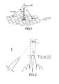
- FIG. 1 An example of a solution using platforms flying at high altitude as proposed by the Boeing company is represented by way of illustration in Figure 1.
- a platform 1 consisting for example of a cargo type aircraft, flies at an altitude of around some twenty kilometres above the ground and describes curves, more specifically circles, of around one kilometre in diameter about a fixed point situated vertically in line with the desired area of coverage referenced 2.
- Ka band namely the band lying between 24 GHz and 29 GHz, more particularly at 28 GHz
- the above dimensioning makes it possible to uncover a ground area of around 35 km in diameter, with a ground antenna of around 20 cm diameter without this antenna being furnished with tracking means.
- the present invention therefore relates to a method of aligning an antenna, more particularly an antenna having fixed beams with an HAP platform. This method makes it possible among other things to minimize the losses related to the motion of the platform. It is moreover particularly simple and cheap to implement.
- the process for aligning an antenna with a platform flying at high altitude is characterized in that the antenna is aligned with the centre of the curve described by the platform.
- a position of the antenna is detected for which the level of variation in the signal received remains below a threshold.
- the threshold is determined as a function of the variations in gain at the border of the area of coverage. According to a variant, this threshold may be adjustable.
- the antenna is a fixed antenna.
- the present invention therefore relates to a process comprising the following steps:
- the fine adjustment by progressive iteration and the calculation of the variation in residual power are carried out over a determined time interval that corresponds, preferably, to a revolution of the platform.
- the present invention also relates to a terminal linked to the antenna, furnished with means for the implementation of the above process.
- the terminal linked to the antenna comprises among other things means for detecting the power received, means for analyzing the variation in power over time and means indicating that the variation is less than a determined threshold.
- the value of the threshold is stored in a table parameterized as a function of the position of the terminal.
- this terminal may comprise means for displaying the variation in power over time.
- FIG. 2 Represented in Figure 2 is a platform 1 flying at high altitude describing a circle c as well as, diagrammatically by dashed lines, the radiation pattern of a ground antenna A situated vertically in line with the platform and the radiation pattern of an antenna A' situated at the border of the area of coverage.
- the two antennas A and A' point towards the centre p of the circle c described by the platform flying at high altitude.
- the 3 dB aperture of the antenna beam ⁇ 3dB and the maximum gain g(0) are given by the following approximate formulae:
- the boresight deviation angles at the centre of the area and on the edge are respectively equal to
- the values of the gain during alignment of the antenna on the centre of the circle described by the platform fluctuate very slightly, with a maximum value of 0.3 dB which can be chosen as threshold value in accordance with the present invention.
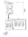
- FIG. 4 Represented diagrammatically in Figure 4 is a terminal associated with a fixed antenna 10 aligned with the centre of the circle described by the platform.
- the antenna is connected to a user terminal consisting of two main subassemblies formed respectively of the ODU 11 or "Outdoor Unit” and of the IDU 13 or "Indoor Unit".
- the ODU is coupled to the directional antenna 10 and is generally situated outside a building whereas the IDU is situated near the user, inside the building.
- the signal transmitted by the HAP platform is received by the terminal in Ka band, namely around 28 GHz. It is firstly amplified then transposed to L band (lying between 1 and 2 GHz) with a constant gain in the ODU 11.
- the ODU comprises circuits well known to the person skilled in the art, namely schematically a duplexer connected to the uplink and the downlink which consist respectively in the case of the uplink of an amplifier AMP, of a mixer and of an amplifier HPA and in the case of the downlink of an amplifier LNA, of a mixer and of an amplifier AMP, the mixers and the amplifiers of the uplink and downlink being connected to one and the same local oscillator.
- the ODU 11 is linked to the IDU 13 by a coaxial cable 14.
- Means allowing the implementation of the process of the present invention are provided in the IDU. These means are represented by the highlighted circuit 15.
- the IDU also comprises, connected to the coaxial cable 14, a duplexer so as to connect to the said coaxial cable the generator of the signal to be transmitted as well as the circuit for processing the signal received.
- the device for the implementation of the present invention essentially comprises a circuit evaluating the power of the signal received, circuits for digitally processing the power signal received and optionally circuits for servocontrol and circuits for controlling the motor whereby the antenna can be pointed towards the platform, as symbolized by the dashed line I.
- the circuit of Figure 3 therefore comprises a detector 150 of the power received, a circuit 151 for digitizing the signal from the detector of the power received followed by a processing circuit 152 that makes it possible to calculate on the basis of the digitized signal, the alteration in the power received over a time interval t that may be chosen, according to one embodiment, equal to a complete revolution of the platform.
- the device can comprise a display system 153 making it possible to represent the alteration in the residual power and which may consist of a Bargraph type system.
- the signal from the circuit 152 may be connected to an optional servocontrol device and is sent to the controls of motors of the antenna.
- the signal from the circuit 152 is compared with a stored threshold corresponding to the maximum value of the residual power variation.
- This threshold value is stored in a table and is dependent on the position of the terminal in the area of coverage.
- the signal from the comparator 155 is sent to a signalling device 156 such as a light-emitting diode or any means of signalling.
- the operator firstly makes a coarse adjustment to the pointing of the antenna in the direction of the platform by searching for the maximum power received by the antenna. Thereafter, the operator refines the pointing of the antenna of the terminal at the centre of the circle described by the HAP platform, doing so by successive iterations. For each pointing attempt, the residual power variation is calculated during a revolution of the HAP. The calculated value is compared with the theoretical value stored in the parameterized table and when the value of the residual variation in the power of the signal received is less than the threshold predefined in this table, an indicator is then activated by the IDU 11 to indicate that the pointing is correct.
- the time for the analysis period will be 33.9 seconds.
- the process of the present invention makes it possible to set up automatic monitoring of the antenna pointing carried out periodically with a servocontrol of the pointing of the antenna through electrical control of motors.
Landscapes
- Mobile Radio Communication Systems (AREA)
Abstract
Description
- The present invention relates to the field of high bit rate wireless networks, more particularly the use of a platform flying at high altitude or HAP (standing for High Altitude Platform) used to ensure cellular coverage of a determined geographical area.
- To be able to make best use of the spectrum of available radio frequencies, it has been proposed, as an alternative to satellites, that a platform flying at an altitude of approximately some twenty kilometres above the ground be used, namely an altitude making it possible to escape the violent winds of the stratosphere.
- The use of a platform flying at high altitude for multimedia communications is described in particular in an article entitled "Providing multimedia communication services from high altitude platforms" published in International Journal of Satellite Communications 2001-19 pp 559 to 580. This article shows the benefit of such a platform in the case of an LMDS system (Local Multipoint Distribution Systems) as compared with a completely terrestrial system. However, it escalates the effects due to the displacement of the platform when the antennas used are fixed antennas or steerable antennas.
- An example of a solution using platforms flying at high altitude as proposed by the Boeing company is represented by way of illustration in Figure 1. In this case, a
platform 1 consisting for example of a cargo type aircraft, flies at an altitude of around some twenty kilometres above the ground and describes curves, more specifically circles, of around one kilometre in diameter about a fixed point situated vertically in line with the desired area of coverage referenced 2. In the case of the Ka band, namely the band lying between 24 GHz and 29 GHz, more particularly at 28 GHz, the above dimensioning makes it possible to uncover a ground area of around 35 km in diameter, with a ground antenna of around 20 cm diameter without this antenna being furnished with tracking means. - In Figure 1, various types of antennas, used to communicate with the
platform 1, have been represented, in particular antennas linked to user terminals or antennas connected to portals for Internet communications. Given the dimensioning of the system mentioned above and having regard to the motion of the platform, the angle of view from the HAP platform varies between around 3.5° vertically in line with the platform and around 1.5° at the border of the area of coverage. - Since the HAP platform is not fixed but describes a curve, one of the main problems encountered during the installation of the antennas, in particular when these antennas are not furnished with means for tracking the platform, relates to the alignment of the antenna with the said platform.
- The present invention therefore relates to a method of aligning an antenna, more particularly an antenna having fixed beams with an HAP platform. This method makes it possible among other things to minimize the losses related to the motion of the platform. It is moreover particularly simple and cheap to implement.
- According to the present invention, the process for aligning an antenna with a platform flying at high altitude is characterized in that the antenna is aligned with the centre of the curve described by the platform.
- According to a preferred embodiment, after having aligned the antenna in the direction of the platform, a position of the antenna is detected for which the level of variation in the signal received remains below a threshold. The threshold is determined as a function of the variations in gain at the border of the area of coverage. According to a variant, this threshold may be adjustable.
- Moreover, according to a preferred embodiment, the antenna is a fixed antenna.
- The present invention therefore relates to a process comprising the following steps:
- coarse adjustment of the pointing of the antenna in the direction of the platform by searching for the maximum power received by the antenna,
- fine adjustment of the alignment of the antenna with the centre of the curve described by the platform by calculating the variation in the residual power and by comparing the value obtained with a threshold.
- Preferably, the fine adjustment by progressive iteration and the calculation of the variation in residual power are carried out over a determined time interval that corresponds, preferably, to a revolution of the platform.
- The present invention also relates to a terminal linked to the antenna, furnished with means for the implementation of the above process. The terminal linked to the antenna comprises among other things means for detecting the power received, means for analyzing the variation in power over time and means indicating that the variation is less than a determined threshold. Preferably, the value of the threshold is stored in a table parameterized as a function of the position of the terminal. Moreover, this terminal may comprise means for displaying the variation in power over time.
- Other characteristics and advantages of the present invention will become apparent on reading the description of an embodiment, this description being given with reference to the appended drawings in which:
- Figure 1 is a diagrammatic perspective view explaining the concept underlying the present invention.
- Figure 2 diagrammatically represents the radiation pattern of a ground antenna situated vertically in line with the platform.
- Figure 3 is a diagrammatic flowchart giving the main steps of the alignment process in accordance with the present invention, and
- Figure 4 is a diagrammatic view of a terminal connected to the antenna implementing the present invention.
-
- Represented in Figure 2 is a
platform 1 flying at high altitude describing a circle c as well as, diagrammatically by dashed lines, the radiation pattern of a ground antenna A situated vertically in line with the platform and the radiation pattern of an antenna A' situated at the border of the area of coverage. - In accordance with the present invention, the two antennas A and A' point towards the centre p of the circle c described by the platform flying at high altitude. In the case represented in Figure 2, the antenna A is situated vertically in line with the platform and, by assuming that the antenna exhibits an axisymmetric radiation pattern in the direction of the maximum, as represented in the figure, the signal received on a given channel is constant and equal to the maximum value that can be received minus Δn where Δn = g(0) - g() where represents the boresight deviation angle and g(0) the maximum gain of the antenna along the axis. When the antenna is not situated vertically in line with the platform, as symbolized by A', the level received by the antenna varies, having regard to the variation in the boresight deviation angle of the
platform 1 with respect to the direction of the antenna's signal maximum. It is apparent that these variations are a minimum when the antenna A or A' is aligned with the centre p of the circle c described by theplatform 1. - The use of the process of the present invention consisting in aligning the antenna with the centre of the curve described by the platform makes it possible in the case of fixed ground antennas, that is to say of antennas devoid of any means for tracking the platform, to use antennas having a restricted diameter. Specifically, as shown hereinbelow, it is unnecessary to increase the size of the antenna beyond a certain diameter. It may be shown that: ΔN () = 12(/ 3dB)2 in which = the boresight deviation angle in degrees and 3dB = the 3 dB aperture of the antenna beam in degrees.
- Moreover, for a given diameter d, the 3 dB aperture of the antenna beam 3dB and the maximum gain g(0) are given by the following approximate formulae:
- 3dB ≅ 65 λ/D, in degrees
- G ≅ 20 log (πD/λ), in dB
-
- Thus, in the case of an embodiment as described in the introduction with the flying platform situated 20 km from the ground and describing a
circle 1 km in diameter covering an area 35 km in diameter and which in the antenna is aligned with the centre of the circle described by the HAP, the boresight deviation angles at the centre of the area and on the edge are respectively equal to - centre = 1.4° and
- edge varying between 0.82° and 0.80°.
-
- In this case, the gain values given in Table 1 below are obtained for various values D of antenna diameter.
D 20 cm 30 cm 40 cm G at the centre of the area 32 dB 33 dB 32 dB G at the border of the area 33.3 dB 36 dB 37.2 dB - The above table shows that at the middle of the area of coverage, an antenna 20 cm in diameter gives a gain equivalent to a 40 cm antenna. Thus, the best compromise between the antenna diameter and the effective gain is for an antenna of between 20 cm and 30 cm in diameter, this corresponding to a gain of between 32 dB and 33 dB.
- Having regard to the fluctuations of the boresight deviation angle edge, the values of the gain during alignment of the antenna on the centre of the circle described by the platform fluctuate very slightly, with a maximum value of 0.3 dB which can be chosen as threshold value in accordance with the present invention.
- A particular embodiment allowing the implementation of the process of the present invention will now be described. The description of this embodiment refers more particularly to Figures 3 and 4. Represented diagrammatically in Figure 4 is a terminal associated with a
fixed antenna 10 aligned with the centre of the circle described by the platform. In a known manner, the antenna is connected to a user terminal consisting of two main subassemblies formed respectively of the ODU 11 or "Outdoor Unit" and of the IDU 13 or "Indoor Unit". The ODU is coupled to thedirectional antenna 10 and is generally situated outside a building whereas the IDU is situated near the user, inside the building. - In a known manner, the signal transmitted by the HAP platform is received by the terminal in Ka band, namely around 28 GHz. It is firstly amplified then transposed to L band (lying between 1 and 2 GHz) with a constant gain in the
ODU 11. The ODU comprises circuits well known to the person skilled in the art, namely schematically a duplexer connected to the uplink and the downlink which consist respectively in the case of the uplink of an amplifier AMP, of a mixer and of an amplifier HPA and in the case of the downlink of an amplifier LNA, of a mixer and of an amplifier AMP, the mixers and the amplifiers of the uplink and downlink being connected to one and the same local oscillator. - In a known manner, the ODU 11 is linked to the IDU 13 by a
coaxial cable 14. Means allowing the implementation of the process of the present invention are provided in the IDU. These means are represented by the highlightedcircuit 15. In a conventional manner the IDU also comprises, connected to thecoaxial cable 14, a duplexer so as to connect to the said coaxial cable the generator of the signal to be transmitted as well as the circuit for processing the signal received. - The device for the implementation of the present invention essentially comprises a circuit evaluating the power of the signal received, circuits for digitally processing the power signal received and optionally circuits for servocontrol and circuits for controlling the motor whereby the antenna can be pointed towards the platform, as symbolized by the dashed line I.
- A more precise embodiment of the device making it possible to align the antenna with the platform and implementing the present invention is represented in Figure 3. The circuit of Figure 3 therefore comprises a
detector 150 of the power received, acircuit 151 for digitizing the signal from the detector of the power received followed by aprocessing circuit 152 that makes it possible to calculate on the basis of the digitized signal, the alteration in the power received over a time interval t that may be chosen, according to one embodiment, equal to a complete revolution of the platform. Optionally, the device can comprise adisplay system 153 making it possible to represent the alteration in the residual power and which may consist of a Bargraph type system. Moreover, the signal from thecircuit 152 may be connected to an optional servocontrol device and is sent to the controls of motors of the antenna. - Moreover, in accordance with the present invention, the signal from the
circuit 152 is compared with a stored threshold corresponding to the maximum value of the residual power variation. This threshold value is stored in a table and is dependent on the position of the terminal in the area of coverage. The signal from thecomparator 155 is sent to asignalling device 156 such as a light-emitting diode or any means of signalling. - The various steps implemented using the device described will now be explained with reference to Figure 4.
- During implementation of the system, the operator firstly makes a coarse adjustment to the pointing of the antenna in the direction of the platform by searching for the maximum power received by the antenna. Thereafter, the operator refines the pointing of the antenna of the terminal at the centre of the circle described by the HAP platform, doing so by successive iterations. For each pointing attempt, the residual power variation is calculated during a revolution of the HAP. The calculated value is compared with the theoretical value stored in the parameterized table and when the value of the residual variation in the power of the signal received is less than the threshold predefined in this table, an indicator is then activated by the
IDU 11 to indicate that the pointing is correct. By way of example, in the case of an HAP positioned as described above, travelling at a constant speed of 400 km per hour with a radius of deployment r of 600 m, the time for the analysis period will be 33.9 seconds. - Various alternatives may be used to implement the process of the present invention. For example, instead of the
user IDU 11 described with reference to Figure 4, it is possible to use an IDU of simplified installation that connects directly to the ODU through a coaxial cable and that makes it possible to facilitate the accurate pointing of the antenna when the latter is located on the roof of a dwelling. - Moreover, the process of the present invention makes it possible to set up automatic monitoring of the antenna pointing carried out periodically with a servocontrol of the pointing of the antenna through electrical control of motors.
Claims (12)
- Process for aligning at least one ground antenna situated in a given area of coverage with a platform flying at high-altitude (HAP), characterized in that the antenna (A or A") is aligned with the centre (p) of the curve @ described by the platform.
- Process according to Claim 1, characterized in that, after having aligned the antenna in the direction of the platform, a position of the antenna is detected for which the level of variation in the signal received remains below a threshold.
- Process according to Claims 1 or 2, characterized in that the threshold is determined as a function of the variations in gain at the border of the area of coverage.
- Process according to Claim 3, characterized in that the threshold is adjustable.
- Process according to one of Claims 1 to 4, characterized in that the antenna is a fixed antenna.
- Process according to Claim 1, characterized in that it comprises the following steps:coarse adjustment of the pointing of the antenna in the direction of the platform by searching for the maximum power received by the antenna,followed by fine adjustment of the alignment of the antenna with the centre of the curve described by the platform by calculating the variation in the residual power and by comparing the value obtained with a threshold.
- Process according to Claim 6, characterized in that the fine adjustment is carried out through successive iterations.
- Process according to Claims 6 and 7, characterized in that the calculation of the variation in residual power is carried out over a determined time interval.
- Process according to Claim 8, characterized in that the time interval corresponds to a revolution of the platform.
- Terminal linked to the antenna for the implementation of the process according to any one of Claims 1 to 9, characterized in that it moreover comprises means for detecting the power received (150), means for analyzing the variation in power over time (152) and means indicating that the variation is less than a determined threshold (155).
- Terminal according to Claim 10, characterized in that the value of the threshold is stored in a table parameterized as a function of the position of the terminal.
- Terminal according to one of Claims 10 and 11, characterized in that it comprises means for displaying the variation in power over time (153).
Applications Claiming Priority (2)
| Application Number | Priority Date | Filing Date | Title |
|---|---|---|---|
| FR0301033A FR2850795A1 (en) | 2003-01-30 | 2003-01-30 | Antenna alignment process for multimedia communication service, involves aligning antenna in center of curve described by high altitude platform, based on result of comparison between variation of residual power and threshold |
| FR0301033 | 2003-01-30 |
Publications (1)
| Publication Number | Publication Date |
|---|---|
| EP1605542A1 true EP1605542A1 (en) | 2005-12-14 |
Family
ID=32696208
Family Applications (1)
| Application Number | Title | Priority Date | Filing Date |
|---|---|---|---|
| EP04100243A Withdrawn EP1605542A1 (en) | 2003-01-30 | 2004-01-23 | Process for aligning at least one ground antenna with a platform flying at high altitude |
Country Status (2)
| Country | Link |
|---|---|
| EP (1) | EP1605542A1 (en) |
| FR (1) | FR2850795A1 (en) |
Citations (3)
| Publication number | Priority date | Publication date | Assignee | Title |
|---|---|---|---|---|
| JPS5817706A (en) * | 1981-07-24 | 1983-02-02 | Toshiba Corp | Antenna device |
| US6011511A (en) * | 1996-11-07 | 2000-01-04 | Samsung Electronics Co., Ltd. | Satellite dish positioning system |
| US6393281B1 (en) * | 1993-03-26 | 2002-05-21 | At&T Wireless Services Inc | Seamless hand-off for air-to-ground systems |
-
2003
- 2003-01-30 FR FR0301033A patent/FR2850795A1/en active Pending
-
2004
- 2004-01-23 EP EP04100243A patent/EP1605542A1/en not_active Withdrawn
Patent Citations (3)
| Publication number | Priority date | Publication date | Assignee | Title |
|---|---|---|---|---|
| JPS5817706A (en) * | 1981-07-24 | 1983-02-02 | Toshiba Corp | Antenna device |
| US6393281B1 (en) * | 1993-03-26 | 2002-05-21 | At&T Wireless Services Inc | Seamless hand-off for air-to-ground systems |
| US6011511A (en) * | 1996-11-07 | 2000-01-04 | Samsung Electronics Co., Ltd. | Satellite dish positioning system |
Non-Patent Citations (5)
| Title |
|---|
| DOVIS F ET AL: "4G COMMUNICATIONS BASED ON HIGH ALTITUDE STRATOSPHERIC PLATFORMS: CHANNEL MODELING AND PERFORMANCE EVALUATION", GLOBECOM'01. 2001 IEEE GLOBAL TELECOMMUNICATIONS CONFERENCE. SAN ANTONIO, TX, NOV. 25 - 29, 2001, IEEE GLOBAL TELECOMMUNICATIONS CONFERENCE, NEW YORK, NY : IEEE, US, vol. VOL. 1 OF 6, 25 November 2001 (2001-11-25), pages 557 - 561, XP001090317, ISBN: 0-7803-7206-9 * |
| KONEFAL T ET AL: "Site diversity for high-altitude platforms: a method for the prediction of joint site attenuation statistics", IEE PROCEEDINGS: MICROWAVES, ANTENNAS AND PROPAGATION, IEE, STEVENAGE, HERTS, GB, vol. 149, no. 2, 3 May 2002 (2002-05-03), pages 124 - 128, XP006018379, ISSN: 1350-2417 * |
| PATENT ABSTRACTS OF JAPAN vol. 007, no. 094 (E - 171) 20 April 1983 (1983-04-20) * |
| THORNTON J ET AL: "BROADBAND COMMUNICATIONS FROM A HIGH-ALTITUDE PLATFORM: THE EUROPEAN HELINET PROGRAMME", ELECTRONICS AND COMMUNICATION ENGINEERING JOURNAL, INSTITUTION OF ELECTRICAL ENGINEERS, LONDON, GB, vol. 13, no. 3, June 2001 (2001-06-01), pages 138 - 144, XP001058773, ISSN: 0954-0695 * |
| TOZER T C ET AL: "HIGH-ALTITUDE PLATFORMS FOR WIRELESS COMMUNICATIONS", ELECTRONICS AND COMMUNICATION ENGINEERING JOURNAL, INSTITUTION OF ELECTRICAL ENGINEERS, LONDON, GB, vol. 13, no. 3, June 2001 (2001-06-01), pages 127 - 137, XP001058772, ISSN: 0954-0695 * |
Also Published As
| Publication number | Publication date |
|---|---|
| FR2850795A1 (en) | 2004-08-06 |
Similar Documents
| Publication | Publication Date | Title |
|---|---|---|
| US6070051A (en) | Method and apparatus for predicting service availability for a ground-to-satellite radio of a communication system | |
| US5946603A (en) | Method and apparatus to respond to a blockage environment in a communication system | |
| CN113438006B (en) | Satellite signal capturing method, device, system and storage medium | |
| US10903898B1 (en) | Changing antenna direction based on satellite blockage detection | |
| EP0998060A2 (en) | Method for enhancing performance of open-loop power control algorithms for satellite communications systems | |
| CN116208221A (en) | Ultra-low orbit satellite ground station data transmission tracking method and related equipment | |
| Kubista et al. | Ka-band propagation measurements and statistics for land mobile satellite applications | |
| Omote et al. | Highly accurate vegetation loss model with seasonal characteristics for high-altitude platform station | |
| Hatsuda et al. | Ku-band long distance site-diversity (SD) characteristics using new measuring system | |
| EP1035664A1 (en) | Satellite communication system with interference mitigation | |
| Miura et al. | Ka-band aeronautical satellite communications experiments using COMETS | |
| Rahim et al. | Estimation of communication link on Ground Sensor Terminal (GST) system for nanosatellite (UiTMSAT-1) store-and-forward mission | |
| Horak et al. | Frequency dependence of attenuation due to vegetation for satellite services | |
| Machado et al. | The Ka-and Q-band AlphaSat ground station in Vigo | |
| Marchetti et al. | Performance trends at 26 GHz for a receiving ground station at polar latitudes: The SNOWBEAR project | |
| Obiyemi et al. | Evaluation of rain degraded digital satellite television reception in tropical regions | |
| Kostulski et al. | Ka band Propagation Experiments on the Australian Low-Earth Orbit Microsatellite “FedSat” | |
| Mohamad Rahim et al. | Installation of UiTM’s ground station–Connecting earth and space with amateur band communication | |
| Vilhar et al. | Satellite propagation experiment in Ljubljana: Beacon measurements at Ka-and Q-band | |
| Kimura et al. | Measurement and analysis of building entry loss in High base station environment | |
| Cavdar et al. | Propagation measurements at L-band for land mobile satellite link design | |
| Saito et al. | Field measurement on simple vehicle-mounted antenna system using a geostationary satellite | |
| Fiser et al. | Experiences with special Ka-and Q-band receivers for Alphasat signal monitoring in Prague, CZ | |
| Rudd | Building penetration loss for slant-paths at L-, S-and C-band | |
| Omote et al. | Propagation Loss Model with Human Body Shielding for High-Altitude Platform Station Communications |
Legal Events
| Date | Code | Title | Description |
|---|---|---|---|
| PUAI | Public reference made under article 153(3) epc to a published international application that has entered the european phase |
Free format text: ORIGINAL CODE: 0009012 |
|
| AK | Designated contracting states |
Kind code of ref document: A1 Designated state(s): AT BE BG CH CY CZ DE DK EE ES FI FR GB GR HU IE IT LI LU MC NL PT RO SE SI SK TR |
|
| AX | Request for extension of the european patent |
Extension state: AL LT LV MK |
|
| 17P | Request for examination filed |
Effective date: 20060606 |
|
| 17Q | First examination report despatched |
Effective date: 20060718 |
|
| AKX | Designation fees paid |
Designated state(s): DE FR GB IT |
|
| RAP1 | Party data changed (applicant data changed or rights of an application transferred) |
Owner name: THOMSON LICENSING |
|
| STAA | Information on the status of an ep patent application or granted ep patent |
Free format text: STATUS: THE APPLICATION IS DEEMED TO BE WITHDRAWN |
|
| 18D | Application deemed to be withdrawn |
Effective date: 20120801 |