EP1605278A1 - Scintillator member, scintillator unit, and radiation detector using the same - Google Patents
Scintillator member, scintillator unit, and radiation detector using the same Download PDFInfo
- Publication number
- EP1605278A1 EP1605278A1 EP04717778A EP04717778A EP1605278A1 EP 1605278 A1 EP1605278 A1 EP 1605278A1 EP 04717778 A EP04717778 A EP 04717778A EP 04717778 A EP04717778 A EP 04717778A EP 1605278 A1 EP1605278 A1 EP 1605278A1
- Authority
- EP
- European Patent Office
- Prior art keywords
- scintillator
- rod
- elements
- unit
- element according
- Prior art date
- Legal status (The legal status is an assumption and is not a legal conclusion. Google has not performed a legal analysis and makes no representation as to the accuracy of the status listed.)
- Withdrawn
Links
- 230000005855 radiation Effects 0.000 title claims abstract description 36
- 239000000463 material Substances 0.000 claims abstract description 50
- 230000001681 protective effect Effects 0.000 claims description 18
- 239000011521 glass Substances 0.000 claims description 12
- 238000006243 chemical reaction Methods 0.000 claims description 6
- 239000007769 metal material Substances 0.000 claims description 4
- 229910052751 metal Inorganic materials 0.000 description 11
- 239000002184 metal Substances 0.000 description 11
- 239000011347 resin Substances 0.000 description 9
- 229920005989 resin Polymers 0.000 description 9
- 238000004519 manufacturing process Methods 0.000 description 8
- 238000000034 method Methods 0.000 description 6
- -1 polyparaxylylene Polymers 0.000 description 6
- 229920000052 poly(p-xylylene) Polymers 0.000 description 5
- 239000000758 substrate Substances 0.000 description 5
- OKTJSMMVPCPJKN-UHFFFAOYSA-N Carbon Chemical compound [C] OKTJSMMVPCPJKN-UHFFFAOYSA-N 0.000 description 3
- 229910003481 amorphous carbon Inorganic materials 0.000 description 3
- 229910052799 carbon Inorganic materials 0.000 description 3
- 239000003575 carbonaceous material Substances 0.000 description 3
- 238000010586 diagram Methods 0.000 description 3
- 230000003287 optical effect Effects 0.000 description 3
- 230000000644 propagated effect Effects 0.000 description 3
- 239000000126 substance Substances 0.000 description 3
- 229910052782 aluminium Inorganic materials 0.000 description 2
- XAGFODPZIPBFFR-UHFFFAOYSA-N aluminium Chemical compound [Al] XAGFODPZIPBFFR-UHFFFAOYSA-N 0.000 description 2
- 239000013078 crystal Substances 0.000 description 2
- 238000001704 evaporation Methods 0.000 description 2
- 239000000835 fiber Substances 0.000 description 2
- 238000007740 vapor deposition Methods 0.000 description 2
- CTQNGGLPUBDAKN-UHFFFAOYSA-N O-Xylene Chemical compound CC1=CC=CC=C1C CTQNGGLPUBDAKN-UHFFFAOYSA-N 0.000 description 1
- 238000010521 absorption reaction Methods 0.000 description 1
- 238000000137 annealing Methods 0.000 description 1
- 230000015556 catabolic process Effects 0.000 description 1
- 229910052804 chromium Inorganic materials 0.000 description 1
- 238000001816 cooling Methods 0.000 description 1
- 229910052802 copper Inorganic materials 0.000 description 1
- 238000005520 cutting process Methods 0.000 description 1
- 238000006731 degradation reaction Methods 0.000 description 1
- 238000001514 detection method Methods 0.000 description 1
- 238000009826 distribution Methods 0.000 description 1
- 230000002349 favourable effect Effects 0.000 description 1
- 239000003365 glass fiber Substances 0.000 description 1
- 229910052737 gold Inorganic materials 0.000 description 1
- 229910052749 magnesium Inorganic materials 0.000 description 1
- 229910052759 nickel Inorganic materials 0.000 description 1
- 229910052697 platinum Inorganic materials 0.000 description 1
- 229910052703 rhodium Inorganic materials 0.000 description 1
- 230000035945 sensitivity Effects 0.000 description 1
- 229910052709 silver Inorganic materials 0.000 description 1
- 229910052719 titanium Inorganic materials 0.000 description 1
- 239000008096 xylene Substances 0.000 description 1
Images




Classifications
-
- H—ELECTRICITY
- H10—SEMICONDUCTOR DEVICES; ELECTRIC SOLID-STATE DEVICES NOT OTHERWISE PROVIDED FOR
- H10F—INORGANIC SEMICONDUCTOR DEVICES SENSITIVE TO INFRARED RADIATION, LIGHT, ELECTROMAGNETIC RADIATION OF SHORTER WAVELENGTH OR CORPUSCULAR RADIATION
- H10F39/00—Integrated devices, or assemblies of multiple devices, comprising at least one element covered by group H10F30/00, e.g. radiation detectors comprising photodiode arrays
- H10F39/10—Integrated devices
- H10F39/12—Image sensors
- H10F39/18—Complementary metal-oxide-semiconductor [CMOS] image sensors; Photodiode array image sensors
- H10F39/189—X-ray, gamma-ray or corpuscular radiation imagers
- H10F39/1898—Indirect radiation image sensors, e.g. using luminescent members
-
- H—ELECTRICITY
- H10—SEMICONDUCTOR DEVICES; ELECTRIC SOLID-STATE DEVICES NOT OTHERWISE PROVIDED FOR
- H10F—INORGANIC SEMICONDUCTOR DEVICES SENSITIVE TO INFRARED RADIATION, LIGHT, ELECTROMAGNETIC RADIATION OF SHORTER WAVELENGTH OR CORPUSCULAR RADIATION
- H10F77/00—Constructional details of devices covered by this subclass
- H10F77/40—Optical elements or arrangements
- H10F77/496—Luminescent members, e.g. fluorescent sheets
Definitions
- This invention concerns a scintillator element, a scintillator unit, and a radiation detector using the same for use in X-ray image taking for medical and industrial purposes, etc.
- Scintillators which convert radiation into visible light, are used as radiation detectors in energy discriminators for discriminating X-rays and ⁇ -rays, and image sensors for acquiring radiation images, or the like.
- a scintillator panel described in International Patent Publication No. WO99/66345 Pamphlet (referred to hereinafter as Document 1), wherein a scintillator is formed on a surface of a substrate made of amorphous carbon, etc.
- JP 08-94,758A JP 08-94,758A
- Document 2 JP 08-94,758A
- the shape of the scintillator panel is mostly determined by the shape of the substrate.
- scintillator panels of different shapes had to be prepared in accordance to the type of radiation detector, etc.
- the substrate needs to be made extremely large and since the scintillator must be formed uniformly on such a large substrate, the scintillator panel is extremely difficult to manufacture.
- a normal scintillator panel is limited in the thickness of the scintillator and is not suited for high-energy radiation detection, which requires a thick scintillator.
- It is an object of the present invention is thus to provide a scintillator element, a scintillator unit, and a radiation detector using the same, which, in application to radiation detectors and other products, can accommodate products of various shapes and sizes and especially products of large size.
- the scintillator element according to the present invention has a scintillator formed by being vapor deposited radially onto a side face of a rod-like member.
- a scintillator that can be used in products of various shapes and sizes, it may be considered that a panel, on which a scintillator is to be formed, be simply made compact and a plurality of such panels be arrayed to accommodate for the sizes, etc. of various products.
- a panel on which a scintillator is to be formed, be simply made compact and a plurality of such panels be arrayed to accommodate for the sizes, etc. of various products.
- the panel is made compact, since the panel is plate-like, there is a limit to how compact it can be made.
- a scintillator is formed on the side face of a rod-like member.
- the rod-like member as a supporting member for forming the scintillator and forming the scintillator on the side face thereof, the scintillator element can be made compact readily.
- application to image sensors and other products of various shapes and sizes can be carried out favorably.
- a large product can be manufactured readily by using a large number of the scintillator elements.
- the thickness of the scintillator can be made thick to enable absorption of high-energy radiation that cannot be absorbed by a normal scintillator panel.
- the rod-like member is preferably formed of a material (light transmitting material) that transmits the light emitted from the scintillator.
- the rod-like material being formed of a material that transmits the light emitted from the scintillator
- the light emitted from the scintillator is guided through the rod-like member in the direction of, for example, a supporting plate that supports the rod-like member.
- the light emitted from the scintillator can thus be guided definitely to a desired position.
- Glass is preferable as this light transmitting material. By using glass, when the scintillator emits visible light, the converted visible light can be guided definitely and the scintillator can be supported favorably.
- a mode wherein the rod-like member is formed of a metal material is also possible.
- a scintillator element of high strength can be arranged.
- the light emitted from the scintillator can be reflected by the surface of the rod-like member and thereby guided in a desired direction towards a supporting plate, etc.
- a mode wherein the rod-like member is formed of a carbon-based material is also possible.
- the rod-like member is formed from a carbon-based material, obstruction of the entry of X-rays and other radiation can be prevented.
- a mode wherein the rod-like member has a cylindrical shape is preferable.
- the rod-like member have a cylindrical shape, a plurality of scintillators can be readily positioned uniformly when the plurality of scintillators are to be arrayed on the same plane. Also in forming the scintillator on the rod-like member, the scintillator can be readily formed uniformly from the surface.
- a mode wherein a protective film is formed on the surface of the scintillator is also possible.
- a protective film By forming a protective film on the surface of the scintillator, the scintillator can be protected from physical and chemical damage due to external causes.
- the protective film preferably has a moisture-proof property.
- a scintillator is generally high in deliquescent property. Though degradation due to attachment of moisture occurs when the deliquescent property is high, by the protective film having a moisture-proof property, contact of the scintillator with moisture can be prevented favorably. Deliquescence of the scintillator can thus be prevented favorably.
- a mode wherein a reflecting film is formed on the surface of the scintillator that has been formed on the rod-like member is also preferable.
- a reflecting film being formed on the scintillator surface, the light emitted from the scintillator by scintillation emission upon incidence of radiation can be guided definitely to a desired location without leakage to the exterior of the scintillation member and the light amount of the detected light can be made large.
- a scintillator unit according to the present invention has a scintillator bundle, formed by bundling together any of the above-described scintillator elements.
- a mode having a scintillator column, formed by preparing a plurality of any of the above-described scintillator elements and coaxially positioning the respective rod-like members of the plurality of scintillator elements, is also possible. Even in such a mode in which a plurality of the scintillator elements are positioned coaxially, the scintillator elements can be used in accordance to the shape of a product.
- a mode wherein a fixing member is interposed among a plurality of scintillator elements to thereby fix the plurality of scintillator elements, is also possible.
- a fixing member such as a resin
- a radiation detector according to the present invention has a structure that an image pickup element is connected to the rod-like members of the above-described scintillator unit.
- a mode wherein a photoelectric conversion element is connected to the rod-like members of the above-described scintillator is also possible.
- FIG. 1 is a sectional side view of an image sensor provided with a scintillator unit of the present embodiment
- FIG. 2 is a sectional plan view of the interior thereof.
- the image sensor (radiation detector) M according to the present embodiment has a scintillator unit 1.
- the scintillator unit 1 has a plurality of scintillator elements 2.
- the plurality of scintillator elements 2 are positioned in a state wherein the adjacent scintillator elements 2 are in substantially close contact with each other.
- each scintillator element 2 has a cylindrical base material 11, that is, a rod-like member having a scintillator 12, which converts X-rays, ⁇ -rays, or other radiation to light of a predetermined wavelength, formed radially across the entire circumference of its side face.
- a scintillator 12 which converts X-rays, ⁇ -rays, or other radiation to light of a predetermined wavelength, formed radially across the entire circumference of its side face.
- Tl-doped CsI is used in the scintillator 12, and CsI has a structure wherein a plurality of needle-like crystals (columnar crystals) are bristled together.
- This scintillator 12 is formed by performing vapor deposition on the circumferential surface of the base material 11.
- the scintillator 12 of the present embodiment emits visible light upon incidence of X-rays.
- the base material 11 is formed of glass, has a radiation transmitting property, and is arranged so that light is propagated through the interior thereof. Besides glass, the base material 11 may be formed of amorphous carbon or other material having carbon as the main component.
- FIG. 5A the base material 11 is prepared and this base material is rotated about its axis. While rotating the base material 11, a scintillator component that is to be the material for forming the scintillator is vapor deposited onto the side face of the base material 11. When the scintillator component is vapor deposited while rotating the base material 11 as it is as shown in FIG. 5B, the scintillator 12 grows gradually on the surface of the base material 11. Then when the scintillator 12 has grown to a desired length as shown in FIG. 5C, the rotation of the base material 11 is stopped and the growth of the scintillator 12 is stopped to complete the scintillator element 2.
- a protective film 13 is formed on the surface of the scintillator 12 thus formed on scintillator element 2 and the surface of the scintillator 12 is covered by the protective film 13.
- the protective film 13 is formed, for example, of polyparaxylylene and prevents physical and chemical damage of the scintillator 12. In particular, by using polyparaxylylene, a high moisture-proof property is exhibited. Though the scintillator 12 used here is high in deliquescent property, the deliquescence of the scintillator 12 is prevented by protection by the high moisture-proof property of the polyparaxylylene. Besides the abovementioned polyparaxylylene, a xylene-based resin, such as polyparachloroxylylene may be used as the protective film 13.
- a metal reflecting film 14, to serve as a reflecting film, is formed via the protective film 13 on the surface of the scintillator 12.
- the metal reflecting film 14 is formed, for example, of aluminum or other metal and covers the surface of the scintillator 12 via the protective film 13, and prevents the visible light emitted from the scintillator 12 from leaking to the exterior of the scintillator 12.
- the metal reflecting film 14 may be formed of various materials besides the abovementioned aluminum (Al), and a material containing a substance among the group consisting of Ag, Cr, Cu, Ni, Ti, Mg, Rh, Pt, and Au may be used.
- the plurality of these scintillator elements 2 are contained in a case 3, having a lower face that is opened.
- the case 3 is formed, for example, of a resin having a radiation transmitting property, and a mode is also possible wherein it is formed, for example, of a glass tube or amorphous carbon or other material having carbon as the main component.
- the plurality of the scintillator elements 2 are fixed and bundled together by a fixing member, formed for example of a transparent resin, and is positioned so as to fill the interior of the case 3 as much as possible.
- the fixing member is formed, for example, by solidifying molten resin, and the plurality of the scintillator elements 2 can be fixed by pouring the resin in the molten state into case 3, immersing the plurality of the scintillator elements 2 in the molten resin, and then cooling and solidifying the resin.
- a solid-state image pickup element 20 that serves as an image pickup element.
- An end portion of the base material 11 of the scintillator element 2 is connected to the solid-state image pickup element 20, and the solid-state image pickup element 20 receives the light propagated from the scintillator 12 via the base material 11.
- the visible light emitted directly towards the base material 11 enters as it is into the base material 11, propagates inside the base material 11, and reaches the solid-state image pickup element 20.
- the visible light directed towards the metal reflecting film 14 is reflected by the metal reflecting film 14 and then eventually enters into the base material 11.
- the visible light that has thus entered the base material 11 propagates inside the base material 11 and reaches the solid-state image pickup element 20.
- the radiation entered from the incidence surface of the case 3 thus propagates in straight lines as it is, is converted into visible light by the scintillator 12 of each scintillator element 2, and is propagated to the solid-state image pickup element 20 via the base material 11. Since a radiation image entered from the incidence surface is thus made visible as it is and reaches the solid-state image pickup element 20 as a visible optical image and since this visible optical image is taken, the function as an image sensor is served.
- a scintillator bundle is formed by bundling together the plurality of the scintillator elements 2.
- a scintillator bundle is formed by bundling together the plurality of the scintillator elements 2.
- the scintillator element of the present embodiment can be used favorably.
- the scintillator portion (scintillator unit) to be used in the image sensor can manufactured readily by using a large number of scintillator elements.
- FIGS. 6A to 6C are process diagrams of another manufacturing process of the scintillator elements.
- a suspending member 30 which can hold a plurality of the base materials 11 in a suspending manner, is used.
- base materials 11 glass fibers of 0.5mm diameter and 100mm length are used for example.
- the suspending member 30 has a rotating shaft 31, which extends in the vertical direction, and a suspending rod 32 is mounted to the rotating shaft 31.
- a plurality of the base materials 11, that is, the five base materials 11 in the present embodiment are suspended from the suspending rod 32, and by rotation of the rotating shaft 31, the suspending rod 32 rotates about the rotating shaft 31.
- an evaporator 33 for evaporating scintillator components, is set at a position below the suspending member 30.
- the scintillator components comprising, for example, CsI:T1
- the evaporator 33 is evaporated by means of the evaporator 33.
- Scintillators are thus gradually grown at the circumferences of the base materials 11 as shown in FIG. 6B.
- the scintillators 12 are grown to the desired thickness, for example, 0.5mm as shown in FIG. 6C.
- the scintillator elements 2 are completed.
- Each of the scintillator elements 2, 2 ... that have thus been manufactured is covered and coated with the protective film 13, formed of the polyparaxylylene.
- the plurality of scintillator elements 2 are made to fill and be contained inside a glass tube 40 with gaps being eliminated as much as possible as shown in FIG. 7.
- the interior of the glass tube 40 is filled with a transparent resin, which, after being defoamed, is solidified to form a fixing member 41.
- a scintillator base 42 is thereby manufactured. After the scintillator base 42 has been manufactured, the glass tube 40 and the contents thereof are cut to a length of approximately 20mm using a thin-blade cutter as shown in FIG. 9.
- a protective film 43 which protects the cut surface, is then formed by the same procedure as that for forming the protective film on the surfaces of the scintillator elements 2, and a scintillator unit 50 is thereby manufactured.
- a radiation detector is arranged. 50a and 50b may be used in a reversed arrangement.
- the present invention is not limited to the above-described embodiments.
- a glass base material is used, other materials with light transmitting properties may be used instead.
- a metal base material may be used and in order to prevent obstruction of the incidence of radiation, a carbon-based material may be used.
- each scintillator element which has been formed by performing vapor deposition on the base material, is inserted inside a tubular member of glass or other light transmitting material and the light transmitting tubular member can be used as a light guide for guiding light.
- a cylindrically-shaped base material is used as the rod-like member
- this invention is not limited thereto and a base material of, for example, rectangular columnar shape, elliptical columnar shape, etc. may be used.
- the rod-like member is also not limited to being a columnar body, and for example, a rod-like member of conical shape, rectangular pyramidal shape, or other pyramidal shape or truncated pyramidal shape, or a gourd-like shape, with which a central portion in the height direction is constricted, may be used instead.
- a scintillator bundle is formed by aligning the scintillator elements in directions that intersect (are orthogonal to) the axial direction of the scintillator elements in forming the scintillator unit, a mode wherein the scintillator elements are bundled upon being positioned coaxially is also possible.
- a scintillator bundle that is fixed directly by a fixing member is contained inside the case 3, a mode wherein, for example, at least one of a protective film or a metal reflecting film or other reflecting film is interposed at the inner side of the case is also possible.
- the reflecting film or protective film may be formed by adhesion, etc. on the inner side face of the case 3.
- the scintillator bundle is formed using the fixing member, a mode is also possible wherein the scintillator bundle is formed by fixing the scintillator elements to the case or the solid-state image pickup element.
- a photoelectric conversion element such as a photomultiplier tube
- the arrangement may be used as an image sensor.
- the radiation detector may also be used as an energy discriminator.
- a scintillator element and a scintillator unit can be provided, which, in application to products, such as radiation detectors, can accommodate products of various shapes and sizes and especially products of large size.
- CsI(Tl) is used as the scintillator
- this invention is not limited thereto, and, for example, CsI(Na), NaI(Tl), LiI(Eu), Ki(Tl), etc., may be used instead.
- the scintillator is not limited to a type that emits visible light and may be of a type that emits ultraviolet rays or infrared rays upon incidence of radiation.
- an image pickup element with sensitivity to the light resulting from conversion is used, and preferably, the base material that is to serve as an optical guide has a transmitting property for the light resulting from the conversion.
- the scintillator element and the scintillator unit according to the present invention can be used favorably for preparing scintillator panels of large area and detectors, such as radiation image sensors, and can also be used favorable for preparing radiation image sensors and radiation detectors of various shapes.
Landscapes
- Measurement Of Radiation (AREA)
- Solid State Image Pick-Up Elements (AREA)
- Light Receiving Elements (AREA)
Abstract
Description
- This invention concerns a scintillator element, a scintillator unit, and a radiation detector using the same for use in X-ray image taking for medical and industrial purposes, etc.
- Scintillators, which convert radiation into visible light, are used as radiation detectors in energy discriminators for discriminating X-rays and γ-rays, and image sensors for acquiring radiation images, or the like. As an example of an arrangement using such a scintillator, there is a scintillator panel, described in International Patent Publication No. WO99/66345 Pamphlet (referred to hereinafter as Document 1), wherein a scintillator is formed on a surface of a substrate made of amorphous carbon, etc.
- There is also a distribution type detector, which is described in JP 08-94,758A (referred to hereinafter as Document 2) and is formed by bundling together scintillation fibers that are formed of material of the same quality as a scintillator.
- However, with the scintillator panel disclosed in
Document 1, since the scintillator is formed on the substrate, the shape of the scintillator panel is mostly determined by the shape of the substrate. Thus in order to use such scintillator panels in radiation detectors of various shapes and sizes, etc., scintillator panels of different shapes had to be prepared in accordance to the type of radiation detector, etc. In particular with a scintillator panel to be used in a large product, the substrate needs to be made extremely large and since the scintillator must be formed uniformly on such a large substrate, the scintillator panel is extremely difficult to manufacture. Also, a normal scintillator panel is limited in the thickness of the scintillator and is not suited for high-energy radiation detection, which requires a thick scintillator. - Meanwhile, with the distribution-type detector disclosed in
Document 2, scintillator fibers are simply bundled together. Thus this detector's functions cannot be exhibited adequately in application to a radiation detector, etc. - It is an object of the present invention is thus to provide a scintillator element, a scintillator unit, and a radiation detector using the same, which, in application to radiation detectors and other products, can accommodate products of various shapes and sizes and especially products of large size.
- In order to achieve the above object, the scintillator element according to the present invention has a scintillator formed by being vapor deposited radially onto a side face of a rod-like member.
- To provide a scintillator that can be used in products of various shapes and sizes, it may be considered that a panel, on which a scintillator is to be formed, be simply made compact and a plurality of such panels be arrayed to accommodate for the sizes, etc. of various products. However, even if the panel is made compact, since the panel is plate-like, there is a limit to how compact it can be made.
- Meanwhile, with the scintillator element according to the present invention, a scintillator is formed on the side face of a rod-like member. By thus using the rod-like member as a supporting member for forming the scintillator and forming the scintillator on the side face thereof, the scintillator element can be made compact readily. Thus by adjusting the quantity of such scintillator elements to be used, application to image sensors and other products of various shapes and sizes can be carried out favorably. Especially in cases of manufacturing large products, a large product can be manufactured readily by using a large number of the scintillator elements.
- Furthermore, since the length of the rod-like member can be set freely, by making the length of the rod-like member long, the thickness of the scintillator can be made thick to enable absorption of high-energy radiation that cannot be absorbed by a normal scintillator panel.
- The rod-like member is preferably formed of a material (light transmitting material) that transmits the light emitted from the scintillator.
- By the rod-like material being formed of a material that transmits the light emitted from the scintillator, the light emitted from the scintillator is guided through the rod-like member in the direction of, for example, a supporting plate that supports the rod-like member. The light emitted from the scintillator can thus be guided definitely to a desired position.
- Glass is preferable as this light transmitting material. By using glass, when the scintillator emits visible light, the converted visible light can be guided definitely and the scintillator can be supported favorably.
- A mode wherein the rod-like member is formed of a metal material is also possible. By forming the rod-like member from a metal material, a scintillator element of high strength can be arranged. Also by forming the rod-like member from a metal material, the light emitted from the scintillator can be reflected by the surface of the rod-like member and thereby guided in a desired direction towards a supporting plate, etc.
- A mode wherein the rod-like member is formed of a carbon-based material is also possible. By forming the rod-like member from a carbon-based material, obstruction of the entry of X-rays and other radiation can be prevented.
- A mode wherein the rod-like member has a cylindrical shape is preferable. By making the rod-like member have a cylindrical shape, a plurality of scintillators can be readily positioned uniformly when the plurality of scintillators are to be arrayed on the same plane. Also in forming the scintillator on the rod-like member, the scintillator can be readily formed uniformly from the surface.
- A mode wherein a protective film is formed on the surface of the scintillator is also possible. By forming a protective film on the surface of the scintillator, the scintillator can be protected from physical and chemical damage due to external causes.
- In this case, the protective film preferably has a moisture-proof property. A scintillator is generally high in deliquescent property. Though degradation due to attachment of moisture occurs when the deliquescent property is high, by the protective film having a moisture-proof property, contact of the scintillator with moisture can be prevented favorably. Deliquescence of the scintillator can thus be prevented favorably.
- A mode wherein a reflecting film is formed on the surface of the scintillator that has been formed on the rod-like member is also preferable. By a reflecting film being formed on the scintillator surface, the light emitted from the scintillator by scintillation emission upon incidence of radiation can be guided definitely to a desired location without leakage to the exterior of the scintillation member and the light amount of the detected light can be made large.
- Also in order to achieve the above object, a scintillator unit according to the present invention has a scintillator bundle, formed by bundling together any of the above-described scintillator elements. By thus forming the scintillator unit by bundling together any of the above-described scintillator elements, application to products of various shapes and sizes can be carried out favorably by adjusting the number, etc. of the scintillator elements.
- A mode, having a scintillator column, formed by preparing a plurality of any of the above-described scintillator elements and coaxially positioning the respective rod-like members of the plurality of scintillator elements, is also possible. Even in such a mode in which a plurality of the scintillator elements are positioned coaxially, the scintillator elements can be used in accordance to the shape of a product.
- A mode, wherein a fixing member is interposed among a plurality of scintillator elements to thereby fix the plurality of scintillator elements, is also possible. By thus interposing a fixing member, such as a resin, among the plurality of scintillator elements and thereby fixing the plurality of scintillator elements, the scintillator elements can be fixed securely.
- Also in order to achieve the above object, a radiation detector according to the present invention has a structure that an image pickup element is connected to the rod-like members of the above-described scintillator unit. A mode wherein a photoelectric conversion element is connected to the rod-like members of the above-described scintillator is also possible.
-
- FIG. 1 is a sectional side view of an image sensor provided with a scintillator unit according to the present invention, and FIG. 2 is a sectional plan view thereof.
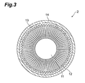
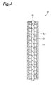
- FIG. 3 is a sectional plan view of a scintillator element of the device of FIGS. 1 and 2 and FIG. 4 is a sectional side view thereof.
- FIGS. 5A to 5C are process diagrams of a manufacturing process of the scintillator element of FIG. 3.
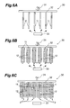
- FIGS. 6A to 6C are process diagrams of another manufacturing process of the scintillator elements of FIG. 3.
- FIG. 7 is a sectional side view showing a state wherein the scintillator elements manufactured by the process of FIGS. 6A to 6C are housed inside a glass tube.
- FIG. 8 is a sectional side view of a scintillator base manufactured using the scintillator elements of FIG. 7.
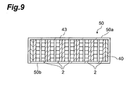
- FIG. 9 is a sectional side view of a scintillator unit prepared by cutting the scintillator base of FIG. 8.
-
- Embodiments of the present invention shall now be described specifically with reference to the drawings. To facilitate the comprehension of the explanation, the same reference numerals denote the same parts, where possible, throughout the drawings, and a repeated explanation will be omitted. Also to facilitate the comprehension of the explanation, the respective drawings may have exaggerated or omitted portions and the dimensional proportions thereof are not necessarily in agreement with actuality.
- FIG. 1 is a sectional side view of an image sensor provided with a scintillator unit of the present embodiment, and FIG. 2 is a sectional plan view of the interior thereof. As shown in FIGS. 1 and 2, the image sensor (radiation detector) M according to the present embodiment has a
scintillator unit 1. Thescintillator unit 1 has a plurality ofscintillator elements 2. As also shown in FIG. 2, the plurality ofscintillator elements 2 are positioned in a state wherein theadjacent scintillator elements 2 are in substantially close contact with each other. - As shown in FIGS. 3 and 4, each
scintillator element 2 has acylindrical base material 11, that is, a rod-like member having ascintillator 12, which converts X-rays, γ-rays, or other radiation to light of a predetermined wavelength, formed radially across the entire circumference of its side face. For example, Tl-doped CsI is used in thescintillator 12, and CsI has a structure wherein a plurality of needle-like crystals (columnar crystals) are bristled together. Thisscintillator 12 is formed by performing vapor deposition on the circumferential surface of thebase material 11. Thescintillator 12 of the present embodiment emits visible light upon incidence of X-rays. - The
base material 11 is formed of glass, has a radiation transmitting property, and is arranged so that light is propagated through the interior thereof. Besides glass, thebase material 11 may be formed of amorphous carbon or other material having carbon as the main component. - A method of manufacturing the
scintillator element 2 shall now be described with reference to FIGS. 5A to 5C. First as shown in FIG. 5A, thebase material 11 is prepared and this base material is rotated about its axis. While rotating thebase material 11, a scintillator component that is to be the material for forming the scintillator is vapor deposited onto the side face of thebase material 11. When the scintillator component is vapor deposited while rotating thebase material 11 as it is as shown in FIG. 5B, thescintillator 12 grows gradually on the surface of thebase material 11. Then when thescintillator 12 has grown to a desired length as shown in FIG. 5C, the rotation of thebase material 11 is stopped and the growth of thescintillator 12 is stopped to complete thescintillator element 2. - A
protective film 13 is formed on the surface of thescintillator 12 thus formed onscintillator element 2 and the surface of thescintillator 12 is covered by theprotective film 13. Theprotective film 13 is formed, for example, of polyparaxylylene and prevents physical and chemical damage of thescintillator 12. In particular, by using polyparaxylylene, a high moisture-proof property is exhibited. Though thescintillator 12 used here is high in deliquescent property, the deliquescence of thescintillator 12 is prevented by protection by the high moisture-proof property of the polyparaxylylene. Besides the abovementioned polyparaxylylene, a xylene-based resin, such as polyparachloroxylylene may be used as theprotective film 13. - Furthermore, a
metal reflecting film 14, to serve as a reflecting film, is formed via theprotective film 13 on the surface of thescintillator 12. Themetal reflecting film 14 is formed, for example, of aluminum or other metal and covers the surface of thescintillator 12 via theprotective film 13, and prevents the visible light emitted from thescintillator 12 from leaking to the exterior of thescintillator 12. Themetal reflecting film 14 may be formed of various materials besides the abovementioned aluminum (Al), and a material containing a substance among the group consisting of Ag, Cr, Cu, Ni, Ti, Mg, Rh, Pt, and Au may be used. - As shown in FIGS. 1 and 2, the plurality of these
scintillator elements 2 are contained in acase 3, having a lower face that is opened. Thecase 3 is formed, for example, of a resin having a radiation transmitting property, and a mode is also possible wherein it is formed, for example, of a glass tube or amorphous carbon or other material having carbon as the main component. The plurality of thescintillator elements 2 are fixed and bundled together by a fixing member, formed for example of a transparent resin, and is positioned so as to fill the interior of thecase 3 as much as possible. The fixing member is formed, for example, by solidifying molten resin, and the plurality of thescintillator elements 2 can be fixed by pouring the resin in the molten state intocase 3, immersing the plurality of thescintillator elements 2 in the molten resin, and then cooling and solidifying the resin. - Furthermore, on the open face of the
case 3 of thescintillator unit 1 is positioned a solid-stateimage pickup element 20 that serves as an image pickup element. An end portion of thebase material 11 of thescintillator element 2 is connected to the solid-stateimage pickup element 20, and the solid-stateimage pickup element 20 receives the light propagated from thescintillator 12 via thebase material 11. - The actions of the image sensor of the present embodiment having the above-described arrangement shall now be described.
- With image sensor M of the present embodiment, radiation enters from an incidence surface at a position opposite the open face of the
case 3. The radiation entered from the incidence surface propagates in straight lines as it is, and is eventually transmitted through themetal reflecting film 14 and theprotective film 13, and reaches thescintillator 12 of eachscintillator element 2. Upon collision of the radiation with thescintillator 12, thescintillator 12 undergoes scintillation emission and light of a predetermined wavelength (visible light in the present embodiment) is generated from thescintillator 12. The visible light generated from thescintillator 12 is emitted directly toward thebase material 11 or themetal reflecting film 14. Here, the visible light emitted directly towards thebase material 11 enters as it is into thebase material 11, propagates inside thebase material 11, and reaches the solid-stateimage pickup element 20. The visible light directed towards themetal reflecting film 14 is reflected by themetal reflecting film 14 and then eventually enters into thebase material 11. The visible light that has thus entered thebase material 11 propagates inside thebase material 11 and reaches the solid-stateimage pickup element 20. - The radiation entered from the incidence surface of the
case 3 thus propagates in straight lines as it is, is converted into visible light by thescintillator 12 of eachscintillator element 2, and is propagated to the solid-stateimage pickup element 20 via thebase material 11. Since a radiation image entered from the incidence surface is thus made visible as it is and reaches the solid-stateimage pickup element 20 as a visible optical image and since this visible optical image is taken, the function as an image sensor is served. - Here with the image sensor of the present embodiment, a scintillator bundle is formed by bundling together the plurality of the
scintillator elements 2. Thus even when, for example, image sensors of different shapes and sizes are to be manufactured, by suitably adjusting the number and manner of bundling together the scintillator elements that form each scintillator bundle, a scintillator bundle, suited to the shape, etc. of the image sensor to be manufactured, can be manufactured readily. Thus regardless of the shape or size of the image sensor, the scintillator element of the present embodiment can be used favorably. Moreover, even when a large image sensor is to be manufactured, the scintillator portion (scintillator unit) to be used in the image sensor can manufactured readily by using a large number of scintillator elements. - The scintillator elements can also be manufactured as follows. FIGS. 6A to 6C are process diagrams of another manufacturing process of the scintillator elements. As shown in FIG. 6A, in this manufacturing process, a suspending
member 30, which can hold a plurality of thebase materials 11 in a suspending manner, is used. Here, asbase materials 11, glass fibers of 0.5mm diameter and 100mm length are used for example. - The suspending
member 30 has arotating shaft 31, which extends in the vertical direction, and a suspendingrod 32 is mounted to therotating shaft 31. A plurality of thebase materials 11, that is, the fivebase materials 11 in the present embodiment are suspended from the suspendingrod 32, and by rotation of therotating shaft 31, the suspendingrod 32 rotates about the rotatingshaft 31. Also, anevaporator 33, for evaporating scintillator components, is set at a position below the suspendingmember 30. - In this state, while rotating the suspending
rod 32, the scintillator components, comprising, for example, CsI:T1, is evaporated by means of theevaporator 33. Scintillators are thus gradually grown at the circumferences of thebase materials 11 as shown in FIG. 6B. By further evaporating the scintillator components by theevaporator 33 while rotating the suspendingrod 32, thescintillators 12 are grown to the desired thickness, for example, 0.5mm as shown in FIG. 6C. Then after a prescribed annealing step, thescintillator elements 2 are completed. By manufacturingscintillator elements 2 by this method, a large amount ofscintillator elements 2 can be manufactured in a short time. - Each of the
scintillator elements protective film 13, formed of the polyparaxylylene. Then as shown in FIG. 7, the plurality ofscintillator elements 2 are made to fill and be contained inside aglass tube 40 with gaps being eliminated as much as possible as shown in FIG. 7. Then as shown in FIG. 8, the interior of theglass tube 40 is filled with a transparent resin, which, after being defoamed, is solidified to form a fixingmember 41. Ascintillator base 42 is thereby manufactured. After thescintillator base 42 has been manufactured, theglass tube 40 and the contents thereof are cut to a length of approximately 20mm using a thin-blade cutter as shown in FIG. 9. Aprotective film 43, which protects the cut surface, is then formed by the same procedure as that for forming the protective film on the surfaces of thescintillator elements 2, and ascintillator unit 50 is thereby manufactured. By making radiation enter from the side of onesurface 50a that intersects the direction of alignment of thescintillator elements 2 of thescintillator unit 50 and positioning a solid-state image pickup element not shown in the figure at the side of theother surface 50b that opposes the one surface, a radiation detector is arranged. 50a and 50b may be used in a reversed arrangement. - Though preferred embodiments of the present invention have been described above, the present invention is not limited to the above-described embodiments. For example, though with the above-described embodiments, a glass base material is used, other materials with light transmitting properties may be used instead. Also in order to increase the strength of the scintillator element, a metal base material may be used and in order to prevent obstruction of the incidence of radiation, a carbon-based material may be used. In a case where a non-light-transmitting member, such as a metal or carbon, is used in the rod-like members, each scintillator element, which has been formed by performing vapor deposition on the base material, is inserted inside a tubular member of glass or other light transmitting material and the light transmitting tubular member can be used as a light guide for guiding light.
- Also with the above-described embodiment, though a cylindrically-shaped base material is used as the rod-like member, this invention is not limited thereto and a base material of, for example, rectangular columnar shape, elliptical columnar shape, etc. may be used. The rod-like member is also not limited to being a columnar body, and for example, a rod-like member of conical shape, rectangular pyramidal shape, or other pyramidal shape or truncated pyramidal shape, or a gourd-like shape, with which a central portion in the height direction is constricted, may be used instead. Also, though with the above-described embodiments, a scintillator bundle is formed by aligning the scintillator elements in directions that intersect (are orthogonal to) the axial direction of the scintillator elements in forming the scintillator unit, a mode wherein the scintillator elements are bundled upon being positioned coaxially is also possible.
- Furthermore, though with the above-described embodiments, a scintillator bundle that is fixed directly by a fixing member is contained inside the
case 3, a mode wherein, for example, at least one of a protective film or a metal reflecting film or other reflecting film is interposed at the inner side of the case is also possible. In this case, the reflecting film or protective film may be formed by adhesion, etc. on the inner side face of thecase 3. Also, though in the above-described embodiments, the scintillator bundle is formed using the fixing member, a mode is also possible wherein the scintillator bundle is formed by fixing the scintillator elements to the case or the solid-state image pickup element. - Meanwhile, though an arrangement wherein a solid-state image pickup element is mounted to the scintillator unit is used as the image sensor, a photoelectric conversion element, such as a photomultiplier tube, may be used instead. In this case, by connecting the photoelectric conversion element to a monitor via a prescribed image processing circuit, the arrangement may be used as an image sensor. Also besides use as an image sensor, the radiation detector may also be used as an energy discriminator.
- As described above, according to the present invention, a scintillator element and a scintillator unit can be provided, which, in application to products, such as radiation detectors, can accommodate products of various shapes and sizes and especially products of large size.
- Also though in the above-described embodiments, CsI(Tl) is used as the scintillator, this invention is not limited thereto, and, for example, CsI(Na), NaI(Tl), LiI(Eu), Ki(Tl), etc., may be used instead. The scintillator is not limited to a type that emits visible light and may be of a type that emits ultraviolet rays or infrared rays upon incidence of radiation. In this case, an image pickup element with sensitivity to the light resulting from conversion is used, and preferably, the base material that is to serve as an optical guide has a transmitting property for the light resulting from the conversion.
- The scintillator element and the scintillator unit according to the present invention can be used favorably for preparing scintillator panels of large area and detectors, such as radiation image sensors, and can also be used favorable for preparing radiation image sensors and radiation detectors of various shapes.
Claims (14)
- A scintillator element comprising:a scintillator vapor deposited radially onto a side face of a rod-like member.
- The scintillator element according to Claim 1, wherein
the rod-like member includes a light transmitting material that transmits the light emitted from the scintillator. - The scintillator element according to Claim 2, wherein
the light transmitting material is glass. - The scintillator element according to Claim 1 or 2, wherein
the rod-like member includes a metal material. - The scintillator element according to Claim 1 or 2, wherein
the rod-like member includes a carbon-base material. - The scintillator element according to any of Claims 1 through 5, wherein
the rod-like member has a cylindrical shape. - The scintillator element according to any of Claims 1 through 6, having a protective film covering the surface of the scintillator formed on the rod-like member.
- The scintillator element according to Claim 7, wherein
the protective film has a moisture-proof property. - The scintillator element according to any of Claims 1 through 8, having a reflecting film formed on the surface of the scintillator formed on the rod-like member.
- A scintillator unit comprising:a scintillator bundle formed by bundling together a plurality of the scintillator elements according to any of Claims 1 through 9.
- A scintillator unit comprising:a scintillator column formed by preparing a plurality of the scintillator elements according to any of Claims 1 through 9 and coaxially positioning the respective rod-like members of the plurality of scintillator elements.
- The scintillator unit according to Claim 10 or 11, further comprising:a fixing member, positioned among the plurality of scintillator elements and fixing the plurality of scintillator elements.
- A radiation detector comprising:the scintillator unit according to any of Claims 10 through 12; andan image pickup element, connected to the rod-like members of the scintillator unit.
- A radiation detector comprising:the scintillator unit according to any of Claims 10 through 12;anda photoelectric conversion element, connected to the rod-like members of the scintillator unit.
Applications Claiming Priority (3)
| Application Number | Priority Date | Filing Date | Title |
|---|---|---|---|
| JP2003063931 | 2003-03-10 | ||
| JP2003063931A JP4377596B2 (en) | 2003-03-10 | 2003-03-10 | Scintillator member, manufacturing method thereof, and scintillator unit |
| PCT/JP2004/002895 WO2004081607A1 (en) | 2003-03-10 | 2004-03-05 | Scintillator member, scintillator unit, and radiation detector using the same |
Publications (2)
| Publication Number | Publication Date |
|---|---|
| EP1605278A1 true EP1605278A1 (en) | 2005-12-14 |
| EP1605278A4 EP1605278A4 (en) | 2015-05-06 |
Family
ID=32984453
Family Applications (1)
| Application Number | Title | Priority Date | Filing Date |
|---|---|---|---|
| EP20040717778 Withdrawn EP1605278A4 (en) | 2003-03-10 | 2004-03-05 | SCINTILLATION ELEMENT, SCINTILLATION UNIT AND RADIATION DETECTOR COMPRISING THIS ELEMENT AND THIS UNIT |
Country Status (4)
| Country | Link |
|---|---|
| US (1) | US7700924B2 (en) |
| EP (1) | EP1605278A4 (en) |
| JP (1) | JP4377596B2 (en) |
| WO (1) | WO2004081607A1 (en) |
Families Citing this family (2)
| Publication number | Priority date | Publication date | Assignee | Title |
|---|---|---|---|---|
| JP2006147554A (en) * | 2004-11-15 | 2006-06-08 | General Electric Co <Ge> | Elliptical gas-filled detector for radiation detection |
| US8044356B2 (en) * | 2006-11-13 | 2011-10-25 | Kabushiki Kaisha Toshiba | Survey meter |
Family Cites Families (15)
| Publication number | Priority date | Publication date | Assignee | Title |
|---|---|---|---|---|
| US4230510A (en) | 1977-11-21 | 1980-10-28 | General Electric Company | Distributed phosphor scintillator structures |
| JPH01229995A (en) | 1988-03-10 | 1989-09-13 | Hamamatsu Photonics Kk | Radiation position detector |
| US5168540A (en) * | 1990-09-12 | 1992-12-01 | Advanced Technology Materials Inc. | Scintillating articles and method of making the same |
| JP2971358B2 (en) | 1994-03-23 | 1999-11-02 | 株式会社東芝 | Radiation measurement device |
| JPH0894758A (en) | 1994-09-26 | 1996-04-12 | Mitsubishi Electric Corp | Distributed detector using scintillation fiber |
| JPH09236669A (en) | 1996-03-01 | 1997-09-09 | Tohoku Electric Power Co Inc | Fiber type radiation detector |
| JPH10307184A (en) * | 1997-05-08 | 1998-11-17 | Hitachi Ltd | Radiation detector |
| KR100688680B1 (en) | 1998-06-18 | 2007-03-02 | 하마마츠 포토닉스 가부시키가이샤 | Scintillator Panel and Radiation Image Sensor |
| US6271510B1 (en) * | 1998-12-18 | 2001-08-07 | Izzie Boxen | Fiber optic gamma camera having scintillating fibers |
| JP2000304865A (en) * | 1999-04-23 | 2000-11-02 | Hitachi Ltd | Optical transmission type radiation measuring device and its measuring system |
| US7373197B2 (en) * | 2000-03-03 | 2008-05-13 | Intramedical Imaging, Llc | Methods and devices to expand applications of intraoperative radiation probes |
| JP2002341038A (en) * | 2001-05-15 | 2002-11-27 | Canon Inc | Method of manufacturing radiation imaging apparatus |
| US6996209B2 (en) * | 2003-10-27 | 2006-02-07 | Ge Medical Systems Global Technology Company, Llc | Scintillator coatings having barrier protection, light transmission, and light reflection properties |
| US6934453B2 (en) * | 2003-11-06 | 2005-08-23 | General Electric Company | Fiber optic brush light detector and method |
| US7732788B2 (en) * | 2007-10-23 | 2010-06-08 | Hamamatsu Photonics K.K. | Radiation image converting panel, scintillator panel and radiation image sensor |
-
2003
- 2003-03-10 JP JP2003063931A patent/JP4377596B2/en not_active Expired - Fee Related
-
2004
- 2004-03-05 WO PCT/JP2004/002895 patent/WO2004081607A1/en not_active Ceased
- 2004-03-05 US US10/548,411 patent/US7700924B2/en not_active Expired - Fee Related
- 2004-03-05 EP EP20040717778 patent/EP1605278A4/en not_active Withdrawn
Non-Patent Citations (1)
| Title |
|---|
| See references of WO2004081607A1 * |
Also Published As
| Publication number | Publication date |
|---|---|
| US7700924B2 (en) | 2010-04-20 |
| EP1605278A4 (en) | 2015-05-06 |
| JP4377596B2 (en) | 2009-12-02 |
| JP2004271392A (en) | 2004-09-30 |
| US20080217549A1 (en) | 2008-09-11 |
| WO2004081607A1 (en) | 2004-09-23 |
Similar Documents
| Publication | Publication Date | Title |
|---|---|---|
| EP1211521B1 (en) | Scintillator panel and radiation image sensor | |
| JP3126715B2 (en) | Scintillator panel and radiation image sensor | |
| EP2411838B1 (en) | Method to optimize the light extraction from scintillator crystals in a solid-state detector | |
| US9377541B2 (en) | Scintillator panel and radiation detector | |
| US7723687B2 (en) | Lanthanide halide microcolumnar scintillators | |
| US7618511B2 (en) | Scintillator panel and method of manufacturing radiation image sensor | |
| EP1684095B1 (en) | Scintillator panel and radiation image sensor | |
| US9496061B2 (en) | Radiographic image conversion panel | |
| US20100127180A1 (en) | Scintillator array and a method of constructing the same | |
| JP6507564B2 (en) | Scintillator panel and radiation detector | |
| WO2010005977A2 (en) | Method and apparatus for x-ray radiographic imaging | |
| JPH09325185A (en) | Radiation detector, manufacturing method thereof, fluoroscopic inspection apparatus, and CT scanner | |
| US20070040125A1 (en) | Scintillator panel, scintillator panel laminate, radiation image sensor using the same, and radiation energy discriminator | |
| EP1139120B1 (en) | Radiation image sensor, and method for manufacturing the same | |
| US10859718B1 (en) | Layered converter for high-resolution neutron radiography | |
| US4621194A (en) | Radiation detecting apparatus | |
| CN111175801A (en) | Radiation detection unit, assembly and system for realizing three-dimensional position sensitivity | |
| US7700924B2 (en) | Scintillator element, scintillator unit, and radiation detector using the same | |
| KR20040028565A (en) | Scintillation detector with gadolinium based sidewall axial restraint and compliance assembly | |
| US6252927B1 (en) | Method of manufacturing a scintillator and a scintillator layer thus manufactured | |
| JP4764039B2 (en) | Phosphor sheet for radiation detector and radiation detector using the same | |
| CN211826538U (en) | Radiation detection unit, assembly and system for realizing three-dimensional position sensitivity | |
| CN109115817B (en) | A kind of Wavelength conversion film and curved detector for curved detector | |
| Kudrolli et al. | Development of high spatial resolution detector for characterization of X-ray optics | |
| JP2004037334A (en) | Radiation imaging device |
Legal Events
| Date | Code | Title | Description |
|---|---|---|---|
| PUAI | Public reference made under article 153(3) epc to a published international application that has entered the european phase |
Free format text: ORIGINAL CODE: 0009012 |
|
| 17P | Request for examination filed |
Effective date: 20050922 |
|
| AK | Designated contracting states |
Kind code of ref document: A1 Designated state(s): AT BE BG CH CY CZ DE DK EE ES FI FR GB GR HU IE IT LI LU MC NL PL PT RO SE SI SK TR |
|
| AX | Request for extension of the european patent |
Extension state: AL LT LV MK |
|
| DAX | Request for extension of the european patent (deleted) | ||
| RBV | Designated contracting states (corrected) |
Designated state(s): DE FR GB IT NL SE |
|
| RA4 | Supplementary search report drawn up and despatched (corrected) |
Effective date: 20150410 |
|
| RIC1 | Information provided on ipc code assigned before grant |
Ipc: G01T 1/20 20060101AFI20150405BHEP Ipc: H01L 27/14 20060101ALI20150405BHEP |
|
| 17Q | First examination report despatched |
Effective date: 20150722 |
|
| STAA | Information on the status of an ep patent application or granted ep patent |
Free format text: STATUS: THE APPLICATION IS DEEMED TO BE WITHDRAWN |
|
| 18D | Application deemed to be withdrawn |
Effective date: 20151202 |