EP1605184A1 - Vibration isolator and method of producing the same - Google Patents
Vibration isolator and method of producing the same Download PDFInfo
- Publication number
- EP1605184A1 EP1605184A1 EP04721636A EP04721636A EP1605184A1 EP 1605184 A1 EP1605184 A1 EP 1605184A1 EP 04721636 A EP04721636 A EP 04721636A EP 04721636 A EP04721636 A EP 04721636A EP 1605184 A1 EP1605184 A1 EP 1605184A1
- Authority
- EP
- European Patent Office
- Prior art keywords
- vibration
- outer casing
- casing member
- fixture
- insert
- Prior art date
- Legal status (The legal status is an assumption and is not a legal conclusion. Google has not performed a legal analysis and makes no representation as to the accuracy of the status listed.)
- Granted
Links
Images


Classifications
-
- F—MECHANICAL ENGINEERING; LIGHTING; HEATING; WEAPONS; BLASTING
- F16—ENGINEERING ELEMENTS AND UNITS; GENERAL MEASURES FOR PRODUCING AND MAINTAINING EFFECTIVE FUNCTIONING OF MACHINES OR INSTALLATIONS; THERMAL INSULATION IN GENERAL
- F16F—SPRINGS; SHOCK-ABSORBERS; MEANS FOR DAMPING VIBRATION
- F16F13/00—Units comprising springs of the non-fluid type as well as vibration-dampers, shock-absorbers, or fluid springs
- F16F13/04—Units comprising springs of the non-fluid type as well as vibration-dampers, shock-absorbers, or fluid springs comprising both a plastics spring and a damper, e.g. a friction damper
- F16F13/06—Units comprising springs of the non-fluid type as well as vibration-dampers, shock-absorbers, or fluid springs comprising both a plastics spring and a damper, e.g. a friction damper the damper being a fluid damper, e.g. the plastics spring not forming a part of the wall of the fluid chamber of the damper
- F16F13/08—Units comprising springs of the non-fluid type as well as vibration-dampers, shock-absorbers, or fluid springs comprising both a plastics spring and a damper, e.g. a friction damper the damper being a fluid damper, e.g. the plastics spring not forming a part of the wall of the fluid chamber of the damper the plastics spring forming at least a part of the wall of the fluid chamber of the damper
- F16F13/10—Units comprising springs of the non-fluid type as well as vibration-dampers, shock-absorbers, or fluid springs comprising both a plastics spring and a damper, e.g. a friction damper the damper being a fluid damper, e.g. the plastics spring not forming a part of the wall of the fluid chamber of the damper the plastics spring forming at least a part of the wall of the fluid chamber of the damper the wall being at least in part formed by a flexible membrane or the like
- F16F13/108—Units comprising springs of the non-fluid type as well as vibration-dampers, shock-absorbers, or fluid springs comprising both a plastics spring and a damper, e.g. a friction damper the damper being a fluid damper, e.g. the plastics spring not forming a part of the wall of the fluid chamber of the damper the plastics spring forming at least a part of the wall of the fluid chamber of the damper the wall being at least in part formed by a flexible membrane or the like characterised by features of plastics springs, e.g. attachment arrangements
-
- F—MECHANICAL ENGINEERING; LIGHTING; HEATING; WEAPONS; BLASTING
- F16—ENGINEERING ELEMENTS AND UNITS; GENERAL MEASURES FOR PRODUCING AND MAINTAINING EFFECTIVE FUNCTIONING OF MACHINES OR INSTALLATIONS; THERMAL INSULATION IN GENERAL
- F16F—SPRINGS; SHOCK-ABSORBERS; MEANS FOR DAMPING VIBRATION
- F16F13/00—Units comprising springs of the non-fluid type as well as vibration-dampers, shock-absorbers, or fluid springs
- F16F13/04—Units comprising springs of the non-fluid type as well as vibration-dampers, shock-absorbers, or fluid springs comprising both a plastics spring and a damper, e.g. a friction damper
- F16F13/06—Units comprising springs of the non-fluid type as well as vibration-dampers, shock-absorbers, or fluid springs comprising both a plastics spring and a damper, e.g. a friction damper the damper being a fluid damper, e.g. the plastics spring not forming a part of the wall of the fluid chamber of the damper
- F16F13/08—Units comprising springs of the non-fluid type as well as vibration-dampers, shock-absorbers, or fluid springs comprising both a plastics spring and a damper, e.g. a friction damper the damper being a fluid damper, e.g. the plastics spring not forming a part of the wall of the fluid chamber of the damper the plastics spring forming at least a part of the wall of the fluid chamber of the damper
- F16F13/10—Units comprising springs of the non-fluid type as well as vibration-dampers, shock-absorbers, or fluid springs comprising both a plastics spring and a damper, e.g. a friction damper the damper being a fluid damper, e.g. the plastics spring not forming a part of the wall of the fluid chamber of the damper the plastics spring forming at least a part of the wall of the fluid chamber of the damper the wall being at least in part formed by a flexible membrane or the like
Definitions
- the present invention has been devised in order to solve the problem described above, and the substance thereof relates to a vibration-proofing apparatus composed of: a mounting fixture, which is joined to either one of a vibration-generating portion and a vibration-receiving portion; an outer casing member made of resin, which is joined to the other of the vibration-receiving portion and the vibration-generating portion; and a rubber resilient body, which is fixed between the mounting fixture and an insert fixture, the insert fixture being arranged along an inner peripheral face of the outer casing member, and the rubber resilient body being attached to the outer casing member via the insert fixture by the outer casing member being inserted between insert fixing portions, in which vibration-proofing apparatus a buffer material is interposed between the outer casing member and the insert fixture.
Landscapes
- Engineering & Computer Science (AREA)
- General Engineering & Computer Science (AREA)
- Mechanical Engineering (AREA)
- Vibration Prevention Devices (AREA)
- Springs (AREA)
- Injection Moulding Of Plastics Or The Like (AREA)
- Combined Devices Of Dampers And Springs (AREA)
- Arrangement Or Mounting Of Propulsion Units For Vehicles (AREA)
Abstract
Description
- The present invention relates to a vibration-proofing apparatus, which is employed at, for example, a vehicle, building machinery, general industrial machinery or the like and which absorbs vibrations from a vibration-generating portion, and a fabrication method thereof. Particularly, it relates to a vibration-proofing apparatus which prevents the generation of looseness, abnormal noises and the like, and a fabrication method thereof.
- Heretofore, between an engine which acts as a vibration-generating portion of a vehicle and a vehicle body which acts as a vibration-receiving portion, a vibration-proofing apparatus which serves as an engine mount has been provided. This vibration-proofing apparatus absorbs vibrations generated by the engine, prevents transmission to the vehicle body side, and improves riding comfort. Such a vibration-proofing apparatus is ordinarily composed of: a mounting fixture, which is joined to either one of the vibration-generating portion and the vibration-receiving portion; an outer casing fixture made of resin, which is joined to the other of the vibration-receiving portion and the vibration-generating portion; and a rubber resilient body fixed between the mounting fixture and the outer casing fixture. Now, in recent years, in accordance with demands for cost reductions, weight reductions and the like, vibration-proofing apparatuses in which the outer casing fixture, which has conventionally been made of metal, is made of resin instead have been developed.
- However, when an outer casing member made of resin is used, differently from the case of an outer casing fixture made of metal, it is not possible to vulcanization-adhere the rubber resilient body to the outer casing member. Therefore, as shown in Figure 3, attachment of a rubber
resilient body 4 to anouter casing member 2 via aninsert fixture 3 is implemented. That is, the rubberresilient body 4 is vulcanization-adhered between a mounting fixture 1 and theinsert fixture 3, theouter casing member 2 is sandwiched byinsert fixing portions 3B, and an inner peripheral face of theouter casing member 2 made of resin is covered with theinsert fixture 3. Thus, the rubberresilient body 4 is attached to theouter casing member 2 without the use of adhesive (see, for example,page 2 and Figure 1 of the publication of Japanese Patent Application Laid-Open (JP-A) No. 2001-50331). - Thus, in the conventional vibration-proofing apparatus shown in Figure 3, rather than the
outer casing member 2 and theinsert fixture 3 being adhered, theinsert fixing portions 3B are embedded in theouter casing member 2, and theouter casing member 2 andinsert fixture 3 are simply pressed together without a gap. Hence, usually, because of the presence of theinsert fixing portions 3B and frictional force, sufficient fixing force is maintained. - However, in resin-molding of the
outer casing member 2, contraction of the resin may be a problem. That is, if theouter casing member 2 made of resin contracts, a gap may occur between theouter casing member 2 and theinsert fixture 3. The occurrence of looseness at theinsert fixture 3 and the generation of abnormal noises and the like because of this gap are a cause of concern. - Accordingly, the present invention has as an objective the provision of a vibration-proofing apparatus which is capable of reliably preventing occurrences of looseness, abnormal noises and the like and a fabrication method thereof, even if, responding to demands for cost reduction, weight reduction and the like by employing an outer casing member made of resin, the outer casing member is unadhered.
- The present invention has been devised in order to solve the problem described above, and the substance thereof relates to a vibration-proofing apparatus composed of: a mounting fixture, which is joined to either one of a vibration-generating portion and a vibration-receiving portion; an outer casing member made of resin, which is joined to the other of the vibration-receiving portion and the vibration-generating portion; and a rubber resilient body, which is fixed between the mounting fixture and an insert fixture, the insert fixture being arranged along an inner peripheral face of the outer casing member, and the rubber resilient body being attached to the outer casing member via the insert fixture by the outer casing member being inserted between insert fixing portions, in which vibration-proofing apparatus a buffer material is interposed between the outer casing member and the insert fixture.
- Further, it relates to a vibration-proofing apparatus in which, preferably, the buffer material is composed of the same rubber as the rubber resilient body and, more preferably, a hole is provided in the insert fixture, and the rubber resilient body and buffer material are integrated by the hole.
- Further, another substance of the present invention relates to a fabrication method of a vibration-proofing apparatus which is composed of: a mounting fixture, which is joined to either one of a vibration-generating portion and a vibration-receiving portion; an outer casing member made of resin, which is joined to the other of the vibration-receiving portion and the vibration-generating portion; and a rubber resilient body, which is fixed between the mounting fixture and an insert fixture, the insert fixture being arranged along an inner peripheral face of the outer casing member, and the rubber resilient body being attached to the outer casing member via the insert fixture by the outer casing member being inserted between insert fixing portions, the vibration-proofing apparatus fabrication method being: preparatorily inserting the insert fixture in a mold for molding of the rubber resilient body, or employing the insert fixture itself as a portion of the mold; causing raw rubber of the rubber resilient body to be packed around a surface of the insert fixture and forming a buffer material, which is composed of the same rubber as the rubber resilient body, integrally at the surface of the insert fixture; thereafter, arranging the insert fixture in a mold at which a cavity corresponding to a shape of the outer casing member is formed; and, by injecting resin into the mold and forming the outer casing member, causing the buffer material to be interposed between the outer casing member and the insert fixture.
- Further, it relates to a vibration-proofing apparatus fabrication method in which, preferably, a hole is provided in the insert fixture, and the raw rubber passes through the hole and is packed around the surface of the insert fixture.
-
- Figure 1 is a sectional view showing an example of a vibration-proofing apparatus of the present invention.
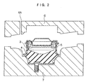
- Figure 2 is a sectional view showing an example of a vibration-proofing apparatus fabrication method of the present invention.
- Figure 3 is a sectional view showing a conventional vibration-proofing apparatus.
-
- A vibration-proofing apparatus of the present invention is an apparatus composed of a mounting fixture joined to either one of a vibration-generating portion and a vibration-receiving portion, an outer casing member joined to the other of the vibration-receiving portion and the vibration-generating portion, and a rubber resilient body. That is, because of vibration-proofing effects of the rubber resilient body, the apparatus features a damping function and an isolation function with respect to inputs of vibrations. The apparatus is between, for example, an engine which acts as the vibration-generating portion of a vehicle and a vehicle body which acts as the vibration-receiving portion, and absorbs vibrations generated by the engine and blocks transmission to the vehicle body side. Thus, the vibration-proofing apparatus of the present invention exhibits similar characteristics to a conventional apparatus in regard to inputs of vibrations during load-bearing.
- Further, in the vibration-proofing apparatus of the present invention, the outer casing member is made of resin. That is, the outer casing fixture, which would conventionally be made of metal, is made of resin instead. Hence, a cost reduction, a weight reduction and the like are anticipated. Herein, because of the impossibility of vulcanization-adhering the rubber resilient body to the outer casing fixture made of resin, the rubber resilient body is vulcanization-adhered between the mounting fixture made of metal and the insert fixture, and the insert fixture is arranged along an inner peripheral face of the outer casing member. Thus, the rubber resilient body is attached to the outer casing member via the insert fixture.
- In this case, if a contraction of the resin occurs in resin-molding of the outer casing member, a gap will occur between the outer casing member and the insert fixture, and looseness, abnormal noises and the like may be generated because of this gap. Accordingly, specifically to the present invention, a buffer material is interposed between the outer casing member and the insert fixture. Thus, even if a contraction occurs at the outer casing member made of resin, because of the presence of the buffer material, a gap will not occur between the outer casing member and the insert fixture.
- Herein, rubber is suitable as the buffer material. In particular, employing the same rubber as the rubber resilient body and forming a rubber layer at an outer peripheral face of the insert fixture is preferable. That is, the rubber resilient body is ordinarily vulcanization-adhered between the mounting fixture and the insert fixture and, at this time, the insert fixture is preparatorily inserted into a mold for molding of the rubber resilient body, or the insert fixture itself is employed as a portion of the mold. Thus, vulcanization-adhesion is implemented simultaneously with curing of raw rubber in the mold. Further, if this raw rubber is packed around a surface of the insert fixture, it is possible to obtain the buffer material simply.
- For example, if a hole is provided in the insert fixture, the raw rubber passes through this hole and is packed around the surface of the insert fixture, and the rubber layer is formed simultaneously with molding. Accordingly, the rubber resilient body and the buffer material will be integrated by the hole of the insert fixture.
- Herebelow, a concrete example of a preferable embodiment of the present invention will be described in accordance with the drawings. Figure 1 is a sectional view showing an example of a vibration-proofing apparatus of the present invention. Further, Figure 2 is a sectional view showing an example of a vibration-proofing apparatus fabrication method of the present invention. The vibration-proofing apparatus of the example shown in Figure 1 is provided with a mounting fixture 1, which is mounted at an engine which is a vibration-generating portion, and an
outer casing member 2, which is mounted at a vehicle body which is a vibration-receiving portion. Here, theouter casing member 2 has been made of resin. Consequently, a reduction in cost, a reduction in weight and the like can be anticipated, but it is not possible to vulcanization-adhere the rubber resilient body. Accordingly, aninsert fixture 3 is arranged along an inner peripheral face of theouter casing member 2. - Further, between the mounting fixture 1 and the
insert fixture 3, a rubberresilient body 4 of NR-type rubber is fixed by vulcanization-adhesion. This rubberresilient body 4 is vulcanization-adhered with the mounting fixture 1 and theinsert fixture 3 in a mold for molding and, at this time, because a hole 3A is provided in theinsert fixture 3, raw rubber passes through the hole 3A and is packed around a surface of theinsert fixture 3. Consequently, abuffer material 5 composed of the same rubber as the rubberresilient body 4 will be integrally formed at the surface of theinsert fixture 3. - Then, as shown in Figure 2, the
insert fixture 3, at which thebuffer material 5 composed of the same rubber as the rubberresilient body 4 is integrally formed, is arranged at alower die 7 and, in a mold in which a cavity corresponding to the shape of theouter casing member 2 is formed by anupper die 6 and thelower die 7, resin is injected through aninjection port 6A of theupper die 6 and forms theouter casing member 2. Consequently, as shown in Figure 1, theouter casing member 2 will be inserted betweeninsert fixing portions 3B, theinsert fixing portions 3B embedded in theouter casing member 2, and the rubberresilient body 4 attached to theouter casing member 2 made of resin, via theinsert fixture 3, without the use of adhesive. Further, thebuffer material 5 composed of the same rubber as the rubberresilient body 4 will be interposed between theouter casing member 2 and theinsert fixture 3. - The vibration-proofing apparatus of the present invention is composed of: a mounting fixture, which is joined to either one of a vibration-generating portion and a vibration-receiving portion; an outer casing member made of resin, which is joined to the other of the vibration-receiving portion and the vibration-generating portion; and a rubber resilient body, which is fixed between the mounting fixture and an insert fixture, the insert fixture being arranged along an inner peripheral face of the outer casing member, and the rubber resilient body being attached to the outer casing member via the insert fixture, in which vibration-proofing apparatus a buffer material is interposed between the outer casing member and the insert fixture. Thus, in addition to effects of cost reduction, weight reduction and the like due to the
outer casing member 2 being made of resin, it is possible to reliably prevent the generation of looseness, abnormal noises and the like, even though the outer casing member is unadhered. Further, according to the vibration-proofing apparatus fabrication method of the present invention, a vibration-proofing apparatus as described above can be fabricated simply.
Claims (5)
- A vibration-proofing apparatus comprising: a mounting fixture (1), which is joined to either one of a vibration-generating portion and a vibration-receiving portion; an outer casing member (2) made of resin, which is joined to the other of the vibration-receiving portion and the vibration-generating portion; and a rubber resilient body (4), which is fixed between the mounting fixture (1) and an insert fixture (3), the insert fixture (3) being arranged along an inner peripheral face of the outer casing member (2), and the rubber resilient body (4) being attached to the outer casing member (2) via the insert fixture (3) by the outer casing member (2) being inserted between insert fixing portions (3B), the vibration-proofing apparatus being characterized by interposition of a buffer material (5) between the outer casing member (2) and the insert fixture (3).
- The vibration-proofing apparatus of claim 1, wherein the buffer material (5) is composed of the same rubber as the rubber resilient body (4).
- The vibration-proofing apparatus of claim 2, wherein a hole (3A) is provided in the insert fixture (3), and the rubber resilient body (4) and buffer material (5) are integrated by the hole (3A).
- A fabrication method of a vibration-proofing apparatus which is composed of: a mounting fixture (1), which is joined to either one of a vibration-generating portion and a vibration-receiving portion; an outer casing member (2) made of resin, which is joined to the other of the vibration-receiving portion and the vibration-generating portion; and a rubber resilient body (4), which is fixed between the mounting fixture (1) and an insert fixture (3), the insert fixture (3) being arranged along an inner peripheral face of the outer casing member (2), and the rubber resilient body (4) being attached to the outer casing member (2) via the insert fixture (3) by the outer casing member (2) being inserted between insert fixing portions (3B), the vibration-proofing apparatus fabrication method comprising: preparatorily inserting the insert fixture (3) in a mold for molding of the rubber resilient body (4), or employing the insert fixture (3) itself as a portion of the mold; causing raw rubber of the rubber resilient body (4) to be packed around a surface of the insert fixture (3) and forming a buffer material (5), which is composed of the same rubber as the rubber resilient body (4), integrally at the surface of the insert fixture (3); arranging the insert fixture (3) in a mold at which a cavity corresponding to a shape of the outer casing member (2) is formed; and, by injecting resin into the mold and forming the outer casing member (2), causing the buffer material (5) to be interposed between the outer casing member (2) and the insert fixture (3).
- The vibration-proofing apparatus fabrication method of claim 4, wherein a hole (3A) is provided in the insert fixture (3), and the raw rubber passes through the hole (3A) and is packed around the surface of the insert fixture (3).
Applications Claiming Priority (3)
| Application Number | Priority Date | Filing Date | Title |
|---|---|---|---|
| JP2003073164 | 2003-03-18 | ||
| JP2003073164 | 2003-03-18 | ||
| PCT/JP2004/003628 WO2004083674A1 (en) | 2003-03-18 | 2004-03-18 | Vibration isolator and method of producing the same |
Publications (3)
| Publication Number | Publication Date |
|---|---|
| EP1605184A1 true EP1605184A1 (en) | 2005-12-14 |
| EP1605184A4 EP1605184A4 (en) | 2006-06-14 |
| EP1605184B1 EP1605184B1 (en) | 2007-08-01 |
Family
ID=33027787
Family Applications (1)
| Application Number | Title | Priority Date | Filing Date |
|---|---|---|---|
| EP04721636A Expired - Lifetime EP1605184B1 (en) | 2003-03-18 | 2004-03-18 | Vibration isolator and method of producing the same |
Country Status (5)
| Country | Link |
|---|---|
| US (1) | US20070176338A1 (en) |
| EP (1) | EP1605184B1 (en) |
| JP (1) | JPWO2004083674A1 (en) |
| DE (1) | DE602004007900T2 (en) |
| WO (1) | WO2004083674A1 (en) |
Cited By (2)
| Publication number | Priority date | Publication date | Assignee | Title |
|---|---|---|---|---|
| FR2903749A1 (en) * | 2006-07-12 | 2008-01-18 | Hutchinson Sa | ANTI-VIBRATION SUPPORT AND METHOD FOR MANUFACTURING THE SAME |
| US7635116B2 (en) | 2005-01-12 | 2009-12-22 | Hutchinson | Method of manufacturing an anti-vibration device, and an anti-vibration device obtainable by the method |
Family Cites Families (5)
| Publication number | Priority date | Publication date | Assignee | Title |
|---|---|---|---|---|
| JPH0689803B2 (en) * | 1990-06-26 | 1994-11-14 | 東海ゴム工業株式会社 | Fluid-filled mounting device |
| JPH0972365A (en) * | 1995-08-31 | 1997-03-18 | Tokai Rubber Ind Ltd | Anti-vibration rubber bush and manufacturing method thereof |
| US5704598A (en) * | 1995-09-12 | 1998-01-06 | Bridgestone Corporation | Vibration isolating apparatus |
| JP3853962B2 (en) * | 1998-03-11 | 2006-12-06 | 株式会社ブリヂストン | Vibration isolator |
| JP4199379B2 (en) * | 1999-08-05 | 2008-12-17 | 株式会社ブリヂストン | Vibration isolator |
-
2004
- 2004-03-18 US US10/549,182 patent/US20070176338A1/en not_active Abandoned
- 2004-03-18 WO PCT/JP2004/003628 patent/WO2004083674A1/en not_active Ceased
- 2004-03-18 JP JP2005503734A patent/JPWO2004083674A1/en active Pending
- 2004-03-18 EP EP04721636A patent/EP1605184B1/en not_active Expired - Lifetime
- 2004-03-18 DE DE602004007900T patent/DE602004007900T2/en not_active Expired - Lifetime
Non-Patent Citations (2)
| Title |
|---|
| No further relevant documents disclosed * |
| See also references of WO2004083674A1 * |
Cited By (2)
| Publication number | Priority date | Publication date | Assignee | Title |
|---|---|---|---|---|
| US7635116B2 (en) | 2005-01-12 | 2009-12-22 | Hutchinson | Method of manufacturing an anti-vibration device, and an anti-vibration device obtainable by the method |
| FR2903749A1 (en) * | 2006-07-12 | 2008-01-18 | Hutchinson Sa | ANTI-VIBRATION SUPPORT AND METHOD FOR MANUFACTURING THE SAME |
Also Published As
| Publication number | Publication date |
|---|---|
| WO2004083674A1 (en) | 2004-09-30 |
| DE602004007900T2 (en) | 2008-04-17 |
| JPWO2004083674A1 (en) | 2006-06-22 |
| US20070176338A1 (en) | 2007-08-02 |
| EP1605184B1 (en) | 2007-08-01 |
| DE602004007900D1 (en) | 2007-09-13 |
| EP1605184A4 (en) | 2006-06-14 |
Similar Documents
| Publication | Publication Date | Title |
|---|---|---|
| KR102484894B1 (en) | Hydraulic mount for vehicle | |
| JP5331329B2 (en) | Anti-vibration device with liquid | |
| JP5506572B2 (en) | Method for manufacturing vibration isolator with resin bracket | |
| US20160186807A1 (en) | Functional Component, in Particular for a Motor Vehicle, Method for Producing a Functional Component, and a Motor Vehicle Having a Functional Component | |
| CN107218344B (en) | Dynamic vibration absorber | |
| JP4625761B2 (en) | Anti-vibration device manufacturing method and apparatus | |
| EP1605184B1 (en) | Vibration isolator and method of producing the same | |
| CN101680503B (en) | Bushing for fixing device and device fixing unit using the same | |
| KR101315771B1 (en) | Enginge mount for vehicle | |
| CN105020332A (en) | Vibration damping device | |
| JP6554007B2 (en) | Vibration isolator and manufacturing method thereof | |
| CN100549456C (en) | connecting bearing | |
| JPH08192442A (en) | Method of manufacturing resin bracket vibration damping device and resin bracket vibration damping device manufactured by this manufacturing method | |
| KR20200050083A (en) | fastener for door trim | |
| JP3891694B2 (en) | Vibration isolator | |
| JP4130196B2 (en) | Vibration isolator | |
| CN115111297A (en) | Vibration-proof device | |
| KR101896576B1 (en) | Decoupler for an anti-vibration mounting device and anti-vibration mounting device comprising such a decopuler | |
| JP2002188689A (en) | Anti-vibration device | |
| CN102537202B (en) | Anti-vibration device | |
| JPH06173990A (en) | Vibration control device integral with resin bracket | |
| JP2608538B2 (en) | Manufacturing method of anti-vibration device | |
| JP5685127B2 (en) | Vibration isolator | |
| CN105299131B (en) | Antihunting device | |
| JP2006189066A (en) | Vibration control device |
Legal Events
| Date | Code | Title | Description |
|---|---|---|---|
| PUAI | Public reference made under article 153(3) epc to a published international application that has entered the european phase |
Free format text: ORIGINAL CODE: 0009012 |
|
| 17P | Request for examination filed |
Effective date: 20050922 |
|
| AK | Designated contracting states |
Kind code of ref document: A1 Designated state(s): AT BE BG CH CY CZ DE DK EE ES FI FR GB GR HU IE IT LI LU MC NL PL PT RO SE SI SK TR |
|
| AX | Request for extension of the european patent |
Extension state: AL LT LV MK |
|
| A4 | Supplementary search report drawn up and despatched |
Effective date: 20060427 |
|
| DAX | Request for extension of the european patent (deleted) | ||
| RBV | Designated contracting states (corrected) |
Designated state(s): DE FR GB |
|
| GRAP | Despatch of communication of intention to grant a patent |
Free format text: ORIGINAL CODE: EPIDOSNIGR1 |
|
| GRAS | Grant fee paid |
Free format text: ORIGINAL CODE: EPIDOSNIGR3 |
|
| GRAA | (expected) grant |
Free format text: ORIGINAL CODE: 0009210 |
|
| AK | Designated contracting states |
Kind code of ref document: B1 Designated state(s): DE FR GB |
|
| REG | Reference to a national code |
Ref country code: GB Ref legal event code: FG4D |
|
| REF | Corresponds to: |
Ref document number: 602004007900 Country of ref document: DE Date of ref document: 20070913 Kind code of ref document: P |
|
| ET | Fr: translation filed | ||
| PLBE | No opposition filed within time limit |
Free format text: ORIGINAL CODE: 0009261 |
|
| STAA | Information on the status of an ep patent application or granted ep patent |
Free format text: STATUS: NO OPPOSITION FILED WITHIN TIME LIMIT |
|
| 26N | No opposition filed |
Effective date: 20080506 |
|
| REG | Reference to a national code |
Ref country code: DE Ref legal event code: R082 Ref document number: 602004007900 Country of ref document: DE Representative=s name: BARDEHLE PAGENBERG PARTNERSCHAFT MBB PATENTANW, DE |
|
| REG | Reference to a national code |
Ref country code: FR Ref legal event code: CA Effective date: 20140812 |
|
| REG | Reference to a national code |
Ref country code: DE Ref legal event code: R082 Ref document number: 602004007900 Country of ref document: DE Representative=s name: BARDEHLE PAGENBERG PARTNERSCHAFT MBB PATENTANW, DE Effective date: 20140828 Ref country code: DE Ref legal event code: R081 Ref document number: 602004007900 Country of ref document: DE Owner name: BRIDGESTONE CORPORATION, JP Free format text: FORMER OWNER: BRIDGESTONE CORP., TOKIO/TOKYO, JP Effective date: 20140828 |
|
| REG | Reference to a national code |
Ref country code: FR Ref legal event code: PLFP Year of fee payment: 13 |
|
| REG | Reference to a national code |
Ref country code: FR Ref legal event code: PLFP Year of fee payment: 14 |
|
| REG | Reference to a national code |
Ref country code: FR Ref legal event code: PLFP Year of fee payment: 15 |
|
| PGFP | Annual fee paid to national office [announced via postgrant information from national office to epo] |
Ref country code: DE Payment date: 20200320 Year of fee payment: 17 Ref country code: GB Payment date: 20200323 Year of fee payment: 17 |
|
| PGFP | Annual fee paid to national office [announced via postgrant information from national office to epo] |
Ref country code: FR Payment date: 20200319 Year of fee payment: 17 |
|
| REG | Reference to a national code |
Ref country code: DE Ref legal event code: R119 Ref document number: 602004007900 Country of ref document: DE |
|
| GBPC | Gb: european patent ceased through non-payment of renewal fee |
Effective date: 20210318 |
|
| PG25 | Lapsed in a contracting state [announced via postgrant information from national office to epo] |
Ref country code: GB Free format text: LAPSE BECAUSE OF NON-PAYMENT OF DUE FEES Effective date: 20210318 Ref country code: FR Free format text: LAPSE BECAUSE OF NON-PAYMENT OF DUE FEES Effective date: 20210331 Ref country code: DE Free format text: LAPSE BECAUSE OF NON-PAYMENT OF DUE FEES Effective date: 20211001 |