EP1605181A1 - Bicycle disk brake pad with welded and adhesively bondered layers - Google Patents
Bicycle disk brake pad with welded and adhesively bondered layers Download PDFInfo
- Publication number
- EP1605181A1 EP1605181A1 EP05010985A EP05010985A EP1605181A1 EP 1605181 A1 EP1605181 A1 EP 1605181A1 EP 05010985 A EP05010985 A EP 05010985A EP 05010985 A EP05010985 A EP 05010985A EP 1605181 A1 EP1605181 A1 EP 1605181A1
- Authority
- EP
- European Patent Office
- Prior art keywords
- backing plate
- friction member
- joined area
- brake pad
- protrusion
- Prior art date
- Legal status (The legal status is an assumption and is not a legal conclusion. Google has not performed a legal analysis and makes no representation as to the accuracy of the status listed.)
- Granted
Links
- 229910052751 metal Inorganic materials 0.000 claims description 16
- 239000002184 metal Substances 0.000 claims description 16
- 238000000034 method Methods 0.000 claims description 13
- 238000003466 welding Methods 0.000 claims description 9
- 229910000838 Al alloy Inorganic materials 0.000 claims description 6
- 229910001069 Ti alloy Inorganic materials 0.000 claims description 5
- 238000005245 sintering Methods 0.000 claims description 3
- 238000005304 joining Methods 0.000 claims description 2
- 239000012790 adhesive layer Substances 0.000 claims 2
- 239000000853 adhesive Substances 0.000 description 6
- 230000001070 adhesive effect Effects 0.000 description 6
- 238000004519 manufacturing process Methods 0.000 description 5
- 230000007246 mechanism Effects 0.000 description 5
- 239000012530 fluid Substances 0.000 description 4
- RYGMFSIKBFXOCR-UHFFFAOYSA-N Copper Chemical group [Cu] RYGMFSIKBFXOCR-UHFFFAOYSA-N 0.000 description 3
- 229910052802 copper Inorganic materials 0.000 description 3
- 239000010949 copper Substances 0.000 description 3
- 239000000463 material Substances 0.000 description 3
- 150000002739 metals Chemical class 0.000 description 3
- 238000002360 preparation method Methods 0.000 description 3
- 239000007858 starting material Substances 0.000 description 3
- KXGFMDJXCMQABM-UHFFFAOYSA-N 2-methoxy-6-methylphenol Chemical compound [CH]OC1=CC=CC([CH])=C1O KXGFMDJXCMQABM-UHFFFAOYSA-N 0.000 description 2
- 230000008901 benefit Effects 0.000 description 2
- 150000001875 compounds Chemical class 0.000 description 2
- 238000010438 heat treatment Methods 0.000 description 2
- 239000005011 phenolic resin Substances 0.000 description 2
- 229920001568 phenolic resin Polymers 0.000 description 2
- 230000004044 response Effects 0.000 description 2
- ATJFFYVFTNAWJD-UHFFFAOYSA-N Tin Chemical compound [Sn] ATJFFYVFTNAWJD-UHFFFAOYSA-N 0.000 description 1
- 238000004026 adhesive bonding Methods 0.000 description 1
- 230000002411 adverse Effects 0.000 description 1
- 239000004020 conductor Substances 0.000 description 1
- 238000010586 diagram Methods 0.000 description 1
- QDOXWKRWXJOMAK-UHFFFAOYSA-N dichromium trioxide Chemical compound O=[Cr]O[Cr]=O QDOXWKRWXJOMAK-UHFFFAOYSA-N 0.000 description 1
- 238000009792 diffusion process Methods 0.000 description 1
- 230000000694 effects Effects 0.000 description 1
- 230000005611 electricity Effects 0.000 description 1
- 230000005484 gravity Effects 0.000 description 1
- 239000011159 matrix material Substances 0.000 description 1
- 238000012986 modification Methods 0.000 description 1
- 230000004048 modification Effects 0.000 description 1
- 230000002093 peripheral effect Effects 0.000 description 1
- 239000000843 powder Substances 0.000 description 1
- 230000008569 process Effects 0.000 description 1
- 238000000926 separation method Methods 0.000 description 1
- 229910001220 stainless steel Inorganic materials 0.000 description 1
- 239000010935 stainless steel Substances 0.000 description 1
- 229910001256 stainless steel alloy Inorganic materials 0.000 description 1
Images




Classifications
-
- B—PERFORMING OPERATIONS; TRANSPORTING
- B62—LAND VEHICLES FOR TRAVELLING OTHERWISE THAN ON RAILS
- B62L—BRAKES SPECIALLY ADAPTED FOR CYCLES
- B62L1/00—Brakes; Arrangements thereof
- B62L1/005—Brakes; Arrangements thereof constructional features of brake elements, e.g. fastening of brake blocks in their holders
-
- F—MECHANICAL ENGINEERING; LIGHTING; HEATING; WEAPONS; BLASTING
- F16—ENGINEERING ELEMENTS AND UNITS; GENERAL MEASURES FOR PRODUCING AND MAINTAINING EFFECTIVE FUNCTIONING OF MACHINES OR INSTALLATIONS; THERMAL INSULATION IN GENERAL
- F16D—COUPLINGS FOR TRANSMITTING ROTATION; CLUTCHES; BRAKES
- F16D69/00—Friction linings; Attachment thereof; Selection of coacting friction substances or surfaces
- F16D69/04—Attachment of linings
- F16D2069/0425—Attachment methods or devices
- F16D2069/0441—Mechanical interlocking, e.g. roughened lining carrier, mating profiles on friction material and lining carrier
-
- F—MECHANICAL ENGINEERING; LIGHTING; HEATING; WEAPONS; BLASTING
- F16—ENGINEERING ELEMENTS AND UNITS; GENERAL MEASURES FOR PRODUCING AND MAINTAINING EFFECTIVE FUNCTIONING OF MACHINES OR INSTALLATIONS; THERMAL INSULATION IN GENERAL
- F16D—COUPLINGS FOR TRANSMITTING ROTATION; CLUTCHES; BRAKES
- F16D69/00—Friction linings; Attachment thereof; Selection of coacting friction substances or surfaces
- F16D69/04—Attachment of linings
- F16D2069/0425—Attachment methods or devices
- F16D2069/045—Bonding
- F16D2069/0458—Bonding metallurgic, e.g. welding, brazing, sintering
-
- F—MECHANICAL ENGINEERING; LIGHTING; HEATING; WEAPONS; BLASTING
- F16—ENGINEERING ELEMENTS AND UNITS; GENERAL MEASURES FOR PRODUCING AND MAINTAINING EFFECTIVE FUNCTIONING OF MACHINES OR INSTALLATIONS; THERMAL INSULATION IN GENERAL
- F16D—COUPLINGS FOR TRANSMITTING ROTATION; CLUTCHES; BRAKES
- F16D69/00—Friction linings; Attachment thereof; Selection of coacting friction substances or surfaces
- F16D69/04—Attachment of linings
- F16D2069/0425—Attachment methods or devices
- F16D2069/045—Bonding
- F16D2069/0466—Bonding chemical, e.g. using adhesives, vulcanising
-
- F—MECHANICAL ENGINEERING; LIGHTING; HEATING; WEAPONS; BLASTING
- F16—ENGINEERING ELEMENTS AND UNITS; GENERAL MEASURES FOR PRODUCING AND MAINTAINING EFFECTIVE FUNCTIONING OF MACHINES OR INSTALLATIONS; THERMAL INSULATION IN GENERAL
- F16D—COUPLINGS FOR TRANSMITTING ROTATION; CLUTCHES; BRAKES
- F16D69/00—Friction linings; Attachment thereof; Selection of coacting friction substances or surfaces
- F16D69/04—Attachment of linings
- F16D2069/0425—Attachment methods or devices
- F16D2069/0491—Tools, machines, processes
Definitions
- the present invention is directed to bicycles and, more particularly, to a bicycle disk brake pad.
- Disk brake pads normally pinch a disk brake rotor that rotates along with the wheel in order to brake the wheel.
- Conventionally known disc brake pads of this type sometime comprise a sintered metal friction member bonded to a stainless steel backing plate, for example.
- the sintered metal friction member usually is produced by diffusion bonding while simultaneously bonding it to the back plate. More specifically, the backing plate is copper plated, and then the metal that is to form the friction member is sintered and bonded to the copper plated surface by exposing the entire structure to elevated temperatures of as much as 900°C. Because the backing plate is exposed to such high temperatures, the metals that can be used to form the backing plate are limited to those with a relatively high specific gravity, such as stainless steel alloys, etc., which are resistant to those temperatures. This makes it impossible to reduce the weight of brake pads, which would be particularly desirable in bicycles.
- One possibility to reduce the weight of the brake pad is to adhesively bond a sintered metal friction member to a lightweight backing plate.
- friction members that are adhesively bonded to the backing plate may have poor separation strength and unsatisfactory bonding strength during hard braking when the brake pad may be subjected to temperatures of around 300°C.
- a bicycle disk brake pad comprises a backing plate and a friction member.
- a first joined area of the friction member is welded to the backing plate, and a second joined area of the friction member is adhesively joined to the backing plate.
- Fig. 1 is a side view of a bicycle 10 with a particular embodiment of a complete disk brake apparatus 12.
- Bicycle 10 is a conventional bicycle with a frame 14 supporting a handlebar 15, front and rear forks 16 (only the front fork is shown), front and rear wheels 17 (only the front wheel is shown), and a drive device comprising a sprocket and chain (not shown). Since the structure of such a conventional bicycle is well known in the field, further description if its structure shall be omitted.
- Disk brake apparatus 12 comprises a brake caliper 21 mounted on front fork 16, a brake rotor 22 attached to a hub 17a of front wheel 17 so that brake rotor 22 rotates integrally with front wheel 17, and a brake operating mechanism 23.
- Brake caliper 21 is attached to front fork 16 near brake rotor 22, and it applies a frictional force to brake rotor 22 in response to the operation of brake operating mechanism 23 to stop the rotation of brake rotor 22 and front wheel 17.
- Brake rotor 22 comprises a centrally disposed hub mounting member 22a attached to hub 17a and a ring-shaped rotor member 22b for contacting brake pads 76.
- brake caliper 21 comprises a housing 50 and a piston unit 51.
- Housing 50 is constructed of a thermally conducting material such as an aluminum alloy, and it comprises a first housing member 52a and a second housing member 52b bolted together in a conventional manner to form a slot to receive brake rotor 22 therebetween.
- Housing members 52a and 52b have substantially the same shape, except that hydraulic tubing 86 for brake operating mechanism 23 is connected to second housing member 52b to supply brake oil to both housing members 52a and 52b.
- Second housing member 52b also has an outwardly extending flange that forms an attachment member 54 for bolting brake caliper 21 to front fork 16.
- piston unit 51 comprises four pistons 74 and a pair of brake pads 76.
- Pistons 74 slidably fit into round cylinders 57a and 57b formed in housing members 52a and 52b so as to move between a brake release position and a braking position.
- Brake pads 76 move integrally with pistons 74.
- the brake pads 76 When pistons 74 move from the brake release position to the braking position, the brake pads 76 also move from the brake release position to the braking position.
- brake pads 76 press against and apply a frictional force to brake rotor 22 to thereby decrease or stop rotation of brake rotor 22 and front wheel 17.
- the brake pads 76 are spaced apart from brake rotor 22, thus allowing brake rotor 22 and front wheel 17 to freely rotate.
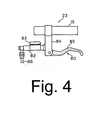
- Brake operating mechanism 23 comprises a brake lever assembly 80, a master cylinder 81, a piston 82, and an operating fluid tank 83.
- Brake lever assembly 80 comprises a bracket 84 mounted on handlebar 15 and a lever component 85 pivotably mounted on bracket 84.
- Bracket 84 is integrally formed with master cylinder 81, and piston 82 and operating fluid tank 83 are supported by bracket 84.
- Piston 82 is slidingly disposed within master cylinder 81, and operating fluid tank 83 is in fluid communication with master cylinder 81.
- One end of piston 82 is connected to lever component 85 so that piston 82 reciprocates inside master cylinder 81 in response to the pulling and releasing of lever component 85.
- Pulling lever component 85 causes pressurized oil to move through the hydraulic tubing 86 connected to brake caliper 21, the pressurized oil moves pistons 74, brake pads 76 contact and apply frictional force to brake rotor 22, and the front wheel 17 is braked.
- brake pad 76 may comprise a friction member 78 made of sintered metal that is laminated to a backing plate 77 made of a light metal such as an aluminum alloy or titanium alloy.
- Friction member 78 may have a thickness of from approximately 2.0 mm to approximately 2.5 mm, for example.
- Backing plate 77 may comprise a sheet made of a lightweight metal such as an aluminum alloy, a titanium alloy, or any other appropriate lightweight metal having a thickness in the range of from approximately 1.5 mm to approximately 1.8 mm, for example.
- Backing plate 77 includes a hook-shaped detent 77a and a round support 77b, both of which are slidably supported by first and second housing members 52a and 52b.
- Backing plate 77 also has convex parts 77c in the form of continuous annular protrusions that protrude toward friction member 78 and are located in the center of backing plate 77.
- Protrusions 77c may protrude from the upper surface of backing plate 77 by approximately 0.1 mm to approximately 0.5 mm, preferably 0.3 mm, for example.
- a welding process described below subsequently eliminates protrusions 77c.
- First joined area 60 is a metal layer that is welded from protrusions 77c and friction member 78 in a manner described below.
- First joined area 60 is a substantially round area that encloses the inner and outer peripheries of protrusions 77c, and it is located substantially in a center of a combination of first joined area 60 and second joined area 61.
- Second joined area 61 is formed around first joined area 60, and it is adhesively bonded to backing plate 77, wherein the adhesive may comprise a phenolic resin adhesive, for example.
- the sintered metal friction member 78 is not joined to backing plate 77 at the same time that friction member 78 is sintered. Instead, the step for sintering friction member 78 and the step for joining friction member 78 to backing plate 77 are separate. As a result, backing plate 77 is not subjected to the high temperatures required for sintering friction member78. This substantially eliminates the restriction on the materials used to fabricate backing plate 77. Thus, in this embodiment, lighter metals such as aluminum alloys or titanium alloys can be used to make backing plate 77, thus resulting in a lighter brake pad 76.
- the adhesively bonded second joined area 61 ensures a basic bonding strength, whereas the welded first joined area 60 ensures that friction member 78 has the same satisfactory bonding strength at both lower and elevated temperatures.
- Fig. 8 is a flow chart of a particular embodiment of a method of fabricating brake pad 76
- Figs. 9A-9E are cross sectional views of brake pad 76 during fabrication.
- Step S1 a sheet of aluminum alloy or titanium alloy (or any of a number of lightweight metals) serving as the matrix for backing plate 77 is prepared in Step S1.
- Step S2 the peripheral shape of backing plate 77 is press formed using a hydraulic punch, for example, and the protrusions 77c are formed in the center.
- Step S3 a short brush treatment is performed on the surface of the sheet to facilitate the adhesion of the adhesive. This completes the preparation of backing plate 77.
- a starting material that is to be sintered to produce friction member 78 is prepared in Step S4.
- the starting material may comprise a metal powder such as dichromium trioxide, tin or compounds thereof, copper or compounds thereof, etc..
- Step S5 a mold is filled with the starting material, and the material is pressed at 900°C so that it is sintered and formed into the desired shape. This concludes the preparation of friction member 78.
- the preparation of backing plate 77 and friction member 78 may be performed separately and simultaneously, or in any desired sequence.
- Step S6 After backing plate 77 and friction member 78 have been prepared, the inner periphery of protrusions 77c and the immediate area around protrusions 77c that is to become the first joined area 60 are masked off in Step S6 to produce the structure shown in Figure 9A.
- Step S7 a phenolic resin adhesive 61 a, for example, is applied to the area which is to become the second joined area 61 to produce the structure shown in Fig. 9B, and then the previously applied mask is removed to produce the structure shown in Fig. 9C.
- Step S8 the prepared friction member 78 is positioned on the adhesively coated backing plate 77 to produce the structure shown in Fig. 9D.
- Step S9 the molds are loaded and pressed at a load of approximately 250 kg, for example, and an electrical potential of approximately 350 V is applied for approximately 10 milliseconds to the first joined area 60.
- the protrusions 77c and the friction member 78 are fused to weld the central portion of friction member 78 to backing plate 77 to form first joined area 60, while friction member 78 is adhesively joined by adhesive 61 a to backing plate 77 to form second joined area 61.
- Step S10 heating for approximately 15 minutes at approximately 180°C in a heating furnace hardens adhesive 61a to complete the fabrication of brake pad 76.
- friction member 78 and backing plate 77 are joined through a combination of welding and adhesive bonding, the parts may be joined more rapidly, with fewer limitations imposed on the material used for backing plate 77. In addition to the more rapid bonding, basic bonding strength as well as bonding strength at both normal and elevated temperatures during use is ensured. The above described method also minimizes adverse effects such as deformation of backing plate 77 or friction member 78 which may occur when the entire friction member 78 is welded to backing plate 77.
- protrusions 77c were formed in the shape of annular protrusions, protrusions 77c may have a number of configurations provided that the flow of electricity can be concentrated during electrical welding. Protrusions 77c may be formed as closed strips in the shape of a rectangular frame, or they need not form a closed shape. Convex components or protrusions also may be provided along the periphery of backing plate 77 to facilitate positioning of friction member 78.
Landscapes
- Engineering & Computer Science (AREA)
- Mechanical Engineering (AREA)
- Braking Arrangements (AREA)
Abstract
Description
Claims (17)
- A bicycle disk brake pad (76) comprising:wherein a first joined area (60) of the friction member is welded to the backing plate; anda backing plate (77);a friction member (78);
wherein a second joined area (61) of the friction member (78) is adhesively joined to the backing plate (77). - The brake pad (76) according to claim 1 wherein the first joined area (60) is located in substantially a center of a combination of the first joined area (60) and the second joined area (61).
- The brake pad (76) according to claim 1 or 2 wherein the first joined area (60) has a curved shape.
- The brake pad according to any of the preceding claims wherein the friction member (78) comprises a sintered metal.
- The brake pad (76) according to any of the preceding claims wherein the backing plate (77) comprises an aluminum alloy.
- The brake pad according to any of claims 1 to 4 wherein the backing plate (77) comprises a titanium alloy.
- A method of forming a brake pad (76) comprising the steps of:providing a metal backing plate (77) with a protrusion (77c);providing a friction member (78) adjacent to the protrusion (77c); andwelding the protrusion (77c) to the friction member (78) to form a first joined area (60).
- The method according to claim 7 further comprising the step of adhesively joining the friction member (78) to the backing plate (77) to form a second joined area (61).
- The method according to claim 8 wherein the first joined area (60) and the second joined area (61) are formed such that the first joined area (60) is located in substantially a center of a combination of the first joined area (60) and the second joined area (61).
- The method according to any of claims 7 to 9 wherein the protrusion (77c) comprises a strip.
- The method according to claim 10 wherein the strip forms a closed area such that a recessed surface of the backing plate (77) faces a surface of the friction member (78).
- The method according to claim 11 wherein the protrusion (77c) is ring-shaped.
- The method according to any of claims 7 to 12 wherein the welding step comprises the step of applying an electrical potential to the protrusion (77c) sufficient to cause the protrusion (77c) to fuse with the friction member (78).
- The method according to claim 13 wherein the welding step comprises the step of applying an electrical potential to the protrusion (77c) sufficient to cause the protrusion (77c) to be eliminated.
- The method according to any of claims 7 to 14 further comprising the step of applying an adhesive layer to the backing plate (77) prior to the welding step.
- The method according to claim 15 further comprising the step of hardening the adhesive layer after the welding step.
- The method according to claim 7 to 16 further comprising the step of sintering the friction member (78) prior to the welding step.
Applications Claiming Priority (2)
| Application Number | Priority Date | Filing Date | Title |
|---|---|---|---|
| JP2004169768 | 2004-06-08 | ||
| JP2004169768A JP2005351288A (en) | 2004-06-08 | 2004-06-08 | Disk brake pad for bicycle |
Publications (2)
| Publication Number | Publication Date |
|---|---|
| EP1605181A1 true EP1605181A1 (en) | 2005-12-14 |
| EP1605181B1 EP1605181B1 (en) | 2010-03-03 |
Family
ID=34936766
Family Applications (1)
| Application Number | Title | Priority Date | Filing Date |
|---|---|---|---|
| EP05010985A Ceased EP1605181B1 (en) | 2004-06-08 | 2005-05-20 | Bicycle disk brake pad with welded and adhesively bondered layers |
Country Status (6)
| Country | Link |
|---|---|
| US (1) | US8342299B2 (en) |
| EP (1) | EP1605181B1 (en) |
| JP (1) | JP2005351288A (en) |
| CN (1) | CN1707131A (en) |
| DE (1) | DE602005019654D1 (en) |
| TW (1) | TW200540348A (en) |
Cited By (2)
| Publication number | Priority date | Publication date | Assignee | Title |
|---|---|---|---|---|
| EP1842767A3 (en) * | 2006-04-04 | 2007-12-26 | Shimano Inc. | Bicycle disk brake pad with titanium backing plate |
| EP2952771A4 (en) * | 2013-02-01 | 2016-10-05 | Sumitomo Bakelite Co | Brake pad and caliper device |
Families Citing this family (11)
| Publication number | Priority date | Publication date | Assignee | Title |
|---|---|---|---|---|
| FR2932236B1 (en) * | 2008-06-04 | 2010-10-15 | Valeo Materiaux De Friction Sa | ATTACHING FRICTION LINING TO A CLUTCH DISC |
| US8550220B2 (en) | 2010-07-01 | 2013-10-08 | Shimano Inc. | Bicycle brake pad |
| TWI441589B (en) * | 2011-01-07 | 2014-06-11 | Taiwan Green Point Entpr Co | A composite structure and its manufacturing method |
| DE102012106162A1 (en) * | 2012-07-10 | 2014-01-30 | Tmd Friction Services Gmbh | Pad carrier plate for a brake pad |
| ITTO20130855A1 (en) * | 2013-10-21 | 2015-04-22 | Itt Italia Srl | METHOD FOR OBTAINING BRAKE PADS AND ASSOCIATED BRAKE PAD |
| KR101557901B1 (en) * | 2014-05-28 | 2015-10-12 | 한국생산기술연구원 | A brake shoe and drum brake and manufactureing method of them |
| JP6329088B2 (en) * | 2015-01-30 | 2018-05-23 | 株式会社シマノ | Brake pad for bicycle and method for manufacturing the same |
| DE102015226809A1 (en) * | 2015-02-24 | 2016-08-25 | Shimano Inc. | Disc brake caliper, brake pad assembly and biasing member assembly |
| JP2018035888A (en) * | 2016-08-31 | 2018-03-08 | 株式会社アドヴィックス | Disk brake device |
| JPWO2019106805A1 (en) * | 2017-11-30 | 2020-11-26 | 昭和電工マテリアルズ株式会社 | Disc brake |
| US11060503B2 (en) * | 2018-03-13 | 2021-07-13 | Wind Solutions, Llc | Yaw pad engagement features |
Citations (3)
| Publication number | Priority date | Publication date | Assignee | Title |
|---|---|---|---|---|
| FR1286058A (en) * | 1961-01-20 | 1962-03-02 | Ferodo Sa | Improvements to friction surface supports for clutches, brakes and other applications |
| US3710071A (en) | 1966-08-26 | 1973-01-09 | U Volker | Method for producing friction discs |
| US4453621A (en) | 1982-06-07 | 1984-06-12 | General Motors Corporation | Drum brake shoe and lining assembly and method of making same |
Family Cites Families (13)
| Publication number | Priority date | Publication date | Assignee | Title |
|---|---|---|---|---|
| US4991697A (en) * | 1989-03-09 | 1991-02-12 | Abex Corporation | Disc brake pad |
| JPH04282037A (en) * | 1991-03-08 | 1992-10-07 | Mitsubishi Materials Corp | Rust-proof back plate |
| JP2652734B2 (en) | 1991-10-04 | 1997-09-10 | 株式会社ミツバ | Bicycle lamp lighting circuit |
| JP3378268B2 (en) | 1992-04-22 | 2003-02-17 | 株式会社シマノ | Bicycle generator |
| CH687749A5 (en) | 1993-02-04 | 1997-02-14 | Michael Kutter | Bicycle lighting system. |
| JPH07329852A (en) | 1994-06-02 | 1995-12-19 | Mitsuoka Denki Seisakusho:Kk | Automatic lighting and illuminating device for bicycle |
| JP3289175B2 (en) | 1995-03-13 | 2002-06-04 | 日信工業株式会社 | Braking members for vehicle brakes |
| GB9515926D0 (en) * | 1995-08-03 | 1995-10-04 | T & N Technology Ltd | Manufacture of brake pads |
| JPH11210792A (en) | 1998-01-23 | 1999-08-03 | Sumitomo Electric Ind Ltd | Disc brake pad and method of manufacturing the same |
| US6206151B1 (en) * | 1999-04-17 | 2001-03-27 | Shimano, Inc. | Ventilated pad for a bicycle disc brake |
| JP2001035673A (en) | 1999-05-18 | 2001-02-09 | Mitsuba Corp | Lighting device for bicycle |
| US20040118645A1 (en) * | 2001-03-27 | 2004-06-24 | Eaton Corporation | Clutch driven disc friction material mounting |
| JP2004088812A (en) | 2002-06-27 | 2004-03-18 | Shimano Inc | Overvoltage protection device for bicycle dynamo |
-
2004
- 2004-06-08 JP JP2004169768A patent/JP2005351288A/en active Pending
-
2005
- 2005-03-22 TW TW094108849A patent/TW200540348A/en unknown
- 2005-04-18 US US10/907,848 patent/US8342299B2/en not_active Expired - Fee Related
- 2005-05-20 EP EP05010985A patent/EP1605181B1/en not_active Ceased
- 2005-05-20 DE DE602005019654T patent/DE602005019654D1/en not_active Expired - Lifetime
- 2005-06-08 CN CN200510076185.5A patent/CN1707131A/en active Pending
Patent Citations (3)
| Publication number | Priority date | Publication date | Assignee | Title |
|---|---|---|---|---|
| FR1286058A (en) * | 1961-01-20 | 1962-03-02 | Ferodo Sa | Improvements to friction surface supports for clutches, brakes and other applications |
| US3710071A (en) | 1966-08-26 | 1973-01-09 | U Volker | Method for producing friction discs |
| US4453621A (en) | 1982-06-07 | 1984-06-12 | General Motors Corporation | Drum brake shoe and lining assembly and method of making same |
Cited By (4)
| Publication number | Priority date | Publication date | Assignee | Title |
|---|---|---|---|---|
| EP1842767A3 (en) * | 2006-04-04 | 2007-12-26 | Shimano Inc. | Bicycle disk brake pad with titanium backing plate |
| US7784593B2 (en) | 2006-04-04 | 2010-08-31 | Shimano, Inc. | Bicycle disk brake pad with a titanium backing plate |
| EP2952771A4 (en) * | 2013-02-01 | 2016-10-05 | Sumitomo Bakelite Co | Brake pad and caliper device |
| US9920801B2 (en) | 2013-02-01 | 2018-03-20 | Sumitomo Bakelite Company Limited | Brake pad and caliper device |
Also Published As
| Publication number | Publication date |
|---|---|
| DE602005019654D1 (en) | 2010-04-15 |
| EP1605181B1 (en) | 2010-03-03 |
| US8342299B2 (en) | 2013-01-01 |
| JP2005351288A (en) | 2005-12-22 |
| CN1707131A (en) | 2005-12-14 |
| TW200540348A (en) | 2005-12-16 |
| US20050269167A1 (en) | 2005-12-08 |
Similar Documents
| Publication | Publication Date | Title |
|---|---|---|
| US8342299B2 (en) | Bicycle disk brake pad with welded and adhesively bonded layers | |
| EP1605180B1 (en) | Bicycle disc brake pad with friction and wear indicating parts | |
| US8365881B2 (en) | Bicycle disk brake apparatus with laminated components | |
| US3306401A (en) | Beryllium containing friction element | |
| EP1842767B1 (en) | Bicycle disk brake pad with titanium backing plate | |
| US7490704B2 (en) | Bicycle disc brake pad | |
| US7516824B2 (en) | Bicycle disk brake pad | |
| TW201341257A (en) | Bicycle brake pad | |
| US6491142B2 (en) | Brake disk | |
| TWI248898B (en) | Bicycle disk brake rotor with laminated components having different thicknesses | |
| US8881873B2 (en) | Bicycle disc brake rotor | |
| JP4996761B2 (en) | Disc rotor for disc brake | |
| US3367774A (en) | Method of producing a composite friction member | |
| EP0725697B1 (en) | SELECTIVELY REINFORCED Al-BASE ALLOY DISC BRAKE CALIPERS | |
| JPH01233604A (en) | Shift fork for transmission |
Legal Events
| Date | Code | Title | Description |
|---|---|---|---|
| PUAI | Public reference made under article 153(3) epc to a published international application that has entered the european phase |
Free format text: ORIGINAL CODE: 0009012 |
|
| AK | Designated contracting states |
Kind code of ref document: A1 Designated state(s): AT BE BG CH CY CZ DE DK EE ES FI FR GB GR HU IE IS IT LI LT LU MC NL PL PT RO SE SI SK TR |
|
| AX | Request for extension of the european patent |
Extension state: AL BA HR LV MK YU |
|
| 17P | Request for examination filed |
Effective date: 20060331 |
|
| RAP1 | Party data changed (applicant data changed or rights of an application transferred) |
Owner name: SHIMANO INC. |
|
| AKX | Designation fees paid |
Designated state(s): AT BE BG DE IT NL |
|
| 17Q | First examination report despatched |
Effective date: 20090311 |
|
| GRAP | Despatch of communication of intention to grant a patent |
Free format text: ORIGINAL CODE: EPIDOSNIGR1 |
|
| GRAS | Grant fee paid |
Free format text: ORIGINAL CODE: EPIDOSNIGR3 |
|
| GRAA | (expected) grant |
Free format text: ORIGINAL CODE: 0009210 |
|
| AK | Designated contracting states |
Kind code of ref document: B1 Designated state(s): DE IT NL |
|
| REF | Corresponds to: |
Ref document number: 602005019654 Country of ref document: DE Date of ref document: 20100415 Kind code of ref document: P |
|
| REG | Reference to a national code |
Ref country code: NL Ref legal event code: VDEP Effective date: 20100303 |
|
| PG25 | Lapsed in a contracting state [announced via postgrant information from national office to epo] |
Ref country code: NL Free format text: LAPSE BECAUSE OF FAILURE TO SUBMIT A TRANSLATION OF THE DESCRIPTION OR TO PAY THE FEE WITHIN THE PRESCRIBED TIME-LIMIT Effective date: 20100303 |
|
| PLBE | No opposition filed within time limit |
Free format text: ORIGINAL CODE: 0009261 |
|
| STAA | Information on the status of an ep patent application or granted ep patent |
Free format text: STATUS: NO OPPOSITION FILED WITHIN TIME LIMIT |
|
| 26N | No opposition filed |
Effective date: 20101206 |
|
| PGFP | Annual fee paid to national office [announced via postgrant information from national office to epo] |
Ref country code: IT Payment date: 20160524 Year of fee payment: 12 |
|
| PG25 | Lapsed in a contracting state [announced via postgrant information from national office to epo] |
Ref country code: IT Free format text: LAPSE BECAUSE OF NON-PAYMENT OF DUE FEES Effective date: 20170520 |
|
| PGFP | Annual fee paid to national office [announced via postgrant information from national office to epo] |
Ref country code: DE Payment date: 20190508 Year of fee payment: 15 |
|
| REG | Reference to a national code |
Ref country code: DE Ref legal event code: R119 Ref document number: 602005019654 Country of ref document: DE |
|
| PG25 | Lapsed in a contracting state [announced via postgrant information from national office to epo] |
Ref country code: DE Free format text: LAPSE BECAUSE OF NON-PAYMENT OF DUE FEES Effective date: 20201201 |