EP1605139B1 - Turbomachine avec moyens de retenue axiale du rotor - Google Patents
Turbomachine avec moyens de retenue axiale du rotor Download PDFInfo
- Publication number
- EP1605139B1 EP1605139B1 EP05105129.0A EP05105129A EP1605139B1 EP 1605139 B1 EP1605139 B1 EP 1605139B1 EP 05105129 A EP05105129 A EP 05105129A EP 1605139 B1 EP1605139 B1 EP 1605139B1
- Authority
- EP
- European Patent Office
- Prior art keywords
- bearing
- turbomachine
- fixed structure
- support element
- stop ring
- Prior art date
- Legal status (The legal status is an assumption and is not a legal conclusion. Google has not performed a legal analysis and makes no representation as to the accuracy of the status listed.)
- Expired - Lifetime
Links
Images


Classifications
-
- F—MECHANICAL ENGINEERING; LIGHTING; HEATING; WEAPONS; BLASTING
- F01—MACHINES OR ENGINES IN GENERAL; ENGINE PLANTS IN GENERAL; STEAM ENGINES
- F01D—NON-POSITIVE DISPLACEMENT MACHINES OR ENGINES, e.g. STEAM TURBINES
- F01D21/00—Shutting-down of machines or engines, e.g. in emergency; Regulating, controlling, or safety means not otherwise provided for
- F01D21/04—Shutting-down of machines or engines, e.g. in emergency; Regulating, controlling, or safety means not otherwise provided for responsive to undesired position of rotor relative to stator or to breaking-off of a part of the rotor, e.g. indicating such position
- F01D21/045—Shutting-down of machines or engines, e.g. in emergency; Regulating, controlling, or safety means not otherwise provided for responsive to undesired position of rotor relative to stator or to breaking-off of a part of the rotor, e.g. indicating such position special arrangements in stators or in rotors dealing with breaking-off of part of rotor
-
- F—MECHANICAL ENGINEERING; LIGHTING; HEATING; WEAPONS; BLASTING
- F01—MACHINES OR ENGINES IN GENERAL; ENGINE PLANTS IN GENERAL; STEAM ENGINES
- F01D—NON-POSITIVE DISPLACEMENT MACHINES OR ENGINES, e.g. STEAM TURBINES
- F01D25/00—Component parts, details, or accessories, not provided for in, or of interest apart from, other groups
- F01D25/16—Arrangement of bearings; Supporting or mounting bearings in casings
Definitions
- the invention relates to the field of turbomachines and in particular turbojet engines with a fan attached to a drive shaft which is supported by at least a first bearing.
- Such a turbojet comprises, from upstream to downstream in the direction of the gas flow, a fan, one or more stages of compressors, a compression chamber, one or more turbine stages and a gas exhaust nozzle.
- the fan comprises a rotor provided with vanes at its periphery which, when they are rotated, drive the air into the turbojet engine.
- the fan rotor is supported by the low pressure rotor shaft of the motor. It is centered on the axis of the turbojet engine by a first bearing which is upstream of a second bearing connected to the fixed structure, in particular the intermediate casing.
- blower is mounted integral with the compressor shaft, which is the low pressure rotor shaft in a double-body engine, this shaft is designated by the single term compressor.
- the first bearing is supported by a support piece, forming a casing around the compressor shaft, oriented downstream of the first bearing and fixed to a fixed structure of the turbojet engine.
- the second bearing is supported by a support piece also attached to a fixed structure of the turbojet engine.
- the structure can be over-sized or, as in the patent FR 2, 752, 024 , propose a decoupling system of the first level.
- the support part of the first bearing is fixed to the structure of the turbojet engine by screws called fusible, having a weakened portion resulting in their rupture in case of excessive forces.
- the support of the second bearing is associated with that of the first bearing to accompany it in case of decoupling, or includes its own decoupling system, independent of that of the first stage. After decoupling, the forces caused by the unbalance are no longer transmitted to the fixed structure of the turbojet engine by the support parts of the bearing or bearings.
- the patent FR 2, 752, 024 proposes in this case to provide, on the fixed structure of the turbojet, a rib surrounding the support part of the first bearing, which is here fixed to that of the second bearing, and fulfilling a function of motion limiter or emergency bearing.
- the rib proposed in the patent FR 2, 752, 024 can however ensure, in the event of rupture of the compressor shaft, an axial retention function of the rotor of the fan, the fastening flange of the support part of the first bearing to the fixed structure of the turbojet then abutting on a wall radial of this rib.
- the document EP 1,308,602 discloses a turbojet engine with two bearings, the second bearing being arranged with a radial clearance in a bore of an annular support to come to bear on said support in case of rupture of decoupling fusible screws.
- the present invention aims to overcome these disadvantages.
- the invention relates to a turbomachine according to claim 1, extending longitudinally along an axis, comprising a rotor, integral with a drive shaft, arranged to rotate about an axis, supported by at least one first bearing, mounted on the fixed structure of the turbomachine by a bearing support part, characterized in that it comprises a stop ring, mounted on the fixed structure of the turbomachine to cooperate with the support part of the first bearing and ensure, in case of displacement of the rotor relative to the fixed structure, a function axially retaining the rotor, homogeneously, without angle effect between the axis of the turbomachine and the axis of the drive shaft.
- the axial retention of the rotor for example in the case of a rupture of the compressor shaft following the loss of a blade of the fan, if the rotor is a fan rotor, homogeneously regardless of the angle between the axis of the compressor and the axis of the turbomachine at the time of restraint.
- This angle which can vary due to the unbalance suffered by the shaft, does not affect the axial retention of the rotor.
- the support part of the first bearing has a bearing intended to cooperate with the surface of a bead of the stop ring.
- the scope is of frustoconical shape.
- the surface of the bead of the stop ring has in axial section a curved shape, symmetrical of revolution about the axis of the turbomachine.
- the curved shape is an arc of a circle.
- the stop ring longitudinally belts the downstream part of the support part of the first bearing, without contact in the normal operating mode of the turbomachine.
- the drive shaft being supported by a second bearing
- the second bearing being mounted on the fixed structure of the turbomachine by a bearing support part
- the support part of the first bearing is fixed to the workpiece.
- supporting the second bearing by fusible screws allowing its decoupling of the support part of the second bearing.
- the drive shaft being supported by a second bearing, the second bearing being mounted on the fixed structure of the turbomachine by a bearing support piece, fixed by screws, the stop ring.
- the stop ring has longitudinal recesses for the passage of said screws to ensure the fixing of the stop ring to the fixed structure of the turbomachine.
- the support part of the first bearing being mounted on the fixed structure of the turbomachine by a device allowing its decoupling with respect to the fixed structure of the turbomachine, the stop ring is arranged not to interfere. on the decoupling phase.
- the support part of the first bearing being mounted on the fixed structure of the turbomachine by a device allowing its decoupling with respect to the fixed structure of the turbomachine, the stop ring is arranged to limit the deflections of the compressor shaft during the decoupling phase.
- the second bearing is mounted on the fixed structure of the turbomachine by a device allowing its decoupling with respect to the fixed structure of the turbomachine.
- the stop ring ensures in particular the axial retention of the rotor in case of breakage of the drive shaft after decoupling the first bearing.
- the invention is particularly applicable to a double-body turbojet, the second bearing is a bearing supporting the low pressure rotor, but the applicant does not intend to limit the scope of its rights to this application.
- the turbojet engine 1 of the invention comprises a fan 2, whose rotor comprises blades 3 extending radially around the axis 4 of the turbojet engine.
- the fan shaft 2 is fixed, downstream of the blades 3, to the compressor shaft 5. This is the low pressure compressor shaft.
- the assembly of the shaft of the fan 2 and of the compressor shaft 5 will be referred to hereinafter as a shaft of the compressor 5, or drive shaft 5.
- the compressor shaft 5 is supported by a first bearing 6 and a second bearing 7, located downstream of the first bearing 6.
- the first bearing 6 comprises an inner ring 8 and an outer ring 9, between which are mounted balls 10 or other rolling members.
- the inner ring 8 is mounted integral with the compressor shaft 5 and the outer ring integral with a bearing support member 11, hereinafter called the support of the first bearing 11.
- the balls 10 allow the rotation of the inner ring 8, therefore of the compressor shaft 5, with respect to the outer ring 9, thus to the support of the first bearing 11.
- the support of the first bearing 11 extends, from the first bearing 6, downstream; it is of slightly frustoconical shape, its diameter increasing downstream.
- the second bearing 7 comprises an inner ring 14 and an outer ring 15, between which are mounted rollers 16 or other rolling members.
- the inner ring 14 is mounted integral with the compressor shaft 5 and the outer ring 15 is mounted integral with the fixed structure of the turbojet engine 1.
- the rollers 16 are mounted parallel to the axis 4 of the turbojet engine 1, in a groove s' extending to the circumference of the inner ring 14, and are held spaced from each other by a cage, well known to those skilled in the art. They allow the rotation of the inner ring 14 with respect to the outer ring 15, and therefore via the compressor shaft 5 with respect to the fixed structure of the turbojet engine 1.
- the second bearing 7 is supported by a bearing support member 19, hereinafter referred to as the support of the second bearing 19, which is generally in the form of a flange extending transversely to the axis 4 of the turbojet engine 1.
- the outer ring 15 of the second bearing 7 comprises, on its outer face, a radial flange 20 fixed to the support of the second bearing 19 by screws 21.
- the support of the second bearing 19 is fixed, by a radial flange 22, to the fixed structure of the turbojet engine 1, here to a housing 23, said intermediate casing 23, by screws 24.
- the support of the first bearing 11 has at its downstream end a stop portion 26, here of greater thickness than its upstream portion.
- This stop portion 26 has in axial section a section in the form of a right triangle.
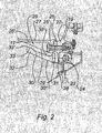
- the inner wall 27 of this stop portion 26 is of cylindrical shape, its downstream wall 28 extends transversely to the axis 4 of the turbojet engine, the inner 27 and downstream 28 walls being connected by a wall 29 having a shape surface generally frustoconical, whose diameter increases downstream, and which corresponds to the hypotenuse of the right triangle defined by the stop portion 26 in axial section.
- the support of the first bearing 11 thus has, in its downstream part, a frustoconical bearing surface 29 constituted by the frustoconical wall 29.
- the stop portion 26 comprises longitudinal recesses 26 'allowing the passage of fusible screws 25 for fixing the support of the first bearing 11 to the flange 22 of the support of the second bearing 19.
- These fusible screws 25 are radially located between the axis 4 of the turbojet engine 1 and the screws 24 for fixing the support of the second bearing 19 to the intermediate casing 23.
- These fusible screws 25 comprise a portion of smaller section 25 ', having a determined tensile strength causing their rupture in case of excessive forces. important, especially when the appearance of an unbalance on the compressor shaft 5, following for example the loss of a blade 3.
- the intermediate casing 23 supports a locking ring 30, which extends around the stop portion 26 of the support of the first bearing 11, longitudinally encircling it, without there being any contact between them in normal operation.
- This stop ring 30 is of frustoconical shape, its diameter increasing towards the rear, its inner and outer walls 30 'being here approximately parallel over most of its length. downstream end, a radial flange 31 by which it is fixed to the intermediate casing 23, here by the screws 24 for fixing the support of the second bearing 19 to the intermediate casing 23.
- the stop ring 30 has, at its upstream end, a bead 32 projecting radially inwards.
- the inner surface 33 of the bead 32 is of convex curved shape, in axial section, in a schematic curve on the figure 2 by the curve portion 33 '.
- the stop ring 30 is arranged so that the surface of the frustoconical bearing surface 29 of the support of the first bearing 11 can abut on the inner surface 33 of its bead 32, if the support of the first bearing 11 is brought to be driven axially forward.
- the function of the stop ring 30 is to block axially, through the support of the first bearing 11, the compressor shaft 5 in case of rupture, so that the fan 2 which is integral with it is not driven towards forward in this case, as will be explained later.
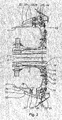
- the induced forces cause the rupture of the fusible screws 25 for fixing the support of the first bearing 11 to the support of the second bearing 19, at their weakened portion 25 '.
- the fusible screws 25 do not all break at the same time, but generally gradually.
- a fusible screw 25 is shown broken on the underside of the figure, while the fusible screw 25 on the upper side is still intact.
- the unbalance induces a bending of the compressor shaft 5, whose axis 5 'is inclined relative to the axis 4 of the turbojet engine 1. This bending of the compressor shaft 5 is authorized by a sliding of the rollers of the second bearing 7 on their outer ring 15, with that said a probable deterioration of this bearing 7.
- the support of the first bearing 11, integral with the compressor shaft 5, is at the same time also inclined with respect to the axis 4 of the turbojet engine 1.
- the surface of the frustoconical bearing surface 29 of the first bearing 11 can then come into abutment on the surface of the wall 33 of the bead 32 of the stop ring 30, in the regions where the fusible screws 25 have broken. Due to the duly optimized shape of the surface 33 of the bead 32, the angle has no effect on this contact, which is homogeneous regardless of the angle considered.
- the stop ring 30 allows, in the embodiment described here, to limit somewhat the bending of the compressor shaft. 5, homogeneously. This bending can also be limited, as is generally the case, because of the consumption of clearance between the ends of the blades 3 of the fan 2 and their retention housing.
- the longitudinal distance between the frustoconical bearing surface 29 of the support of the first bearing 11 and the bead 32 of the locking ring 30 can be dimensioned so that the surfaces of the frustoconical wall 29 and the bead 32 never come into contact during the decoupling phase, so as not to interfere on the latter. It is besides this embodiment that will be preferred, in which the stop ring 30 provides only an axial stop function and no function of limiting radial movements.
- the support of the first bearing 11 is decoupled from the support of the second bearing 19, therefore of the intermediate casing 23, that is to say that it is decoupled from the fixed structure of the turbojet engine 1.
- the forces are no longer then transmitted to the fixed structure of the turbojet engine by the support of the first bearing 11 and the compressor shaft 5 can freely rotate on its axis 5 ', the frustoconical bearing surface 29 the support of the first bearing 11 and the bead 32 of the stop ring 30 not being in contact.
- the support of the first bearing 11 is then also driven forward, as well as the rollers 16 of the second bearing 7, which slide on their outer ring 15.
- this forward leakage is stopped thanks to the stop ring 30, integral with the fixed structure of the turbojet engine 1.
- the frustoconical bearing surface 29 of the support of the first bearing 11 comes into abutment on the wall 33 of the bead 32 of the stop ring 30, which thus ensures the axial stop of the support of the first bearing 11 and therefore of the fan 2, which is not expelled out of the turbojet.
- the rotation of the blower 2 can be prolonged a little, before stopping by friction.
- the curve 33 'defining the inner surface 33 of the bead 32 is optimized so that the abutment of the bearing surface 29 of the first bearing 11 on this surface 33, and therefore the axial stopping of the fan 2, is homogeneous. , independent of the angle that can exist between the axis 5 'of the compressor shaft 5 with the axis 4 of the turbojet engine 1.
- This curved shape of the inner surface 33 of the bead 32 is a meridional curve, in an axial plane, symmetrical of revolution about the axis 4 of the turbojet engine.
- the curve 33 ' is here, in axial sectional view, of circular shape.
- This curve 33 'could be of more complex shape, for example to respect the different phases of decoupling - with or without contact according to the steps.
- the continued rotation of the fan 2 after decoupling the support of the first bearing 11 does not necessarily around the axis 4 of the turbojet 1, precisely precisely the compressor shaft 5 is no longer centered by the first step 6.
- the angle of its axis 5 'with the axis 4 of the turbojet 1 is random. This hazard does not disturb the stop of the blower 2 by the retaining ring 30 due to the optimized shape of the wall 33 of its bead 32.
- the latter also allows, with the continued rotation of the blower 2 related to its advance, to put the blower 2 and the compressor shaft 5 in the axis 4 of the turbojet 1, as is the case on the figure 4 .
- the invention has been described in connection with the support of the first bearing fixed to the fixed structure of the turbojet engine by means of the support of the second bearing, while the stop ring is fixed to the fixed structure of the turbojet engine by the screws of fixing the support of the second bearing to this fixed structure. It goes without saying that the first bearing support, the second bearing support and the stop ring could be fixed to the fixed structure of the turbojet engine independently of each other and perform the same functions that have been described.
- the support of the second bearing could be fixed to this structure by fusible screws.
- the decoupling of the two bearings would be possible, the axial stop by the stop ring intervening only in case of breakage of the compressor shaft.
- the downstream bearing 29 of the first bearing 11 has here been described with a frustoconical shape. It goes without saying that it could also have a curved shape, seen in axial section, this shape being optimized in correlation with the curve 33 'that has the surface 33 of the bead 33 of the locking ring 30 so that the Stopping the blower is done homogeneously, without cornering effect.
- stop ring 30 could also provide an emergency bearing function, acting as a bearing for the compressor shaft 5, in case of rupture of the latter after decoupling of the first bearing 6.
- turbojet engine in particular a double-body turbojet engine whose second bearing is a bearing supporting the low-pressure rotor.
- the invention applies to other types of turbomachines, such as a turboprop, an industrial turbocharger or an industrial turbine, the rotor is not then a fan rotor but simply a rotor.
Landscapes
- Engineering & Computer Science (AREA)
- Mechanical Engineering (AREA)
- General Engineering & Computer Science (AREA)
- Structures Of Non-Positive Displacement Pumps (AREA)
- Mounting Of Bearings Or Others (AREA)
- Supercharger (AREA)
Description
- L'invention concerne le domaine des turbomachines et en particulier des turboréacteurs avec soufflante solidaire d'un arbre d'entraînement qui est supporté par au moins un premier palier.
- Un tel turboréacteur comprend, d'amont en aval dans le sens de l'écoulement des gaz, une soufflante, un ou plusieurs étages de compresseurs, une chambre de compression, un ou plusieurs étages de turbines et une tuyère d'échappement des gaz. La soufflante comporte un rotor pourvu d'aubes à sa périphérie qui, lorsqu'elles sont mises en rotation, entraînent l'air dans le turboréacteur. Le rotor de soufflante est supporté par l'arbre du rotor basse pression du moteur. Il est centré sur l'axe du turboréacteur par un premier palier qui est en amont d'un deuxième palier relié à la structure fixe, notamment le carter intermédiaire.
- Dans la suite de la description, dans la mesure où la soufflante est montée solidaire de l'arbre du compresseur, qui est l'arbre du rotor basse pression dans un moteur à double corps, on désigne cet arbre par l'unique terme arbre du compresseur.
- Le premier palier est supporté par une pièce de support, formant une enveloppe autour de l'arbre du compresseur, orientée vers l'aval du premier palier et fixée à une structure fixe du turboréacteur. Le deuxième palier est supporté par une pièce de support fixée également à une structure fixe du turboréacteur.
- Il peut se produire, accidentellement, la perte d'une aube de soufflante. Il s'ensuit un balourd important sur l'arbre du compresseur, qui entraîne des charges et des vibrations sur les paliers, transmises par leurs pièces de support aux structures fixes du turboréacteur, qui peuvent de ce fait être endommagées.
- Pour prévenir un risque de détérioration trop important du turboréacteur, on peut sur-dimensionner la structure ou, comme dans le brevet
FR 2, 752, 024 - Toutefois, après le découplage d'un ou des deux paliers, la soufflante continue de tourner et l'arbre du compresseur peut ne plus tourner sur son axe et subir des débattements importants pouvant endommager la structure fixe du turboréacteur. Le brevet
FR 2, 752, 024 - La poursuite de la rotation de la soufflante peut néanmoins entraîner des contraintes sur l'arbre de compresseur et l'arbre de turbine, qui sont solidaires, et provoquer la rupture de l'un des deux, ou des deux. On parlera quel que soit le cas de rupture de l'arbre de compresseur. Dans ce cas, la rotation de la soufflante entraîne cette dernière, ainsi que l'arbre de compresseur dont elle est solidaire, vers l'avant. La soufflante est alors expulsée hors du turboréacteur, ce qui doit être évité.
- La nervure proposée dans le brevet
FR 2, 752, 024 - Le document
US 5,791,789 divulgue un canal de guidage radial d'un support de palier d'un rotor en cas de balourd sur le rotor. - Le document
EP 1,308,602 divulgue un turboréacteur avec deux paliers, le deuxième palier étant disposé avec un jeu radial dans un alésage d'un support annulaire pour venir prendre appui sur ledit support en cas de rupture de vis fusibles de découplage. - La présente invention vise à pallier ces inconvénients.
- A cet effet, l'invention concerne une turbomachine selon la revendication 1, s'étendant longitudinalement suivant un axe, comprenant un rotor, solidaire d'un arbre d'entraînement, agencé pour tourner autour d'un axe, supporté par au moins un premier palier, monté sur la structure fixe de la turbomachine par une pièce support de palier, caractérisée par le fait qu'elle comprend un anneau d'arrêt, monté sur la structure fixe de la turbomachine pour coopérer avec la pièce de support du premier palier et assurer, en cas de déplacement du rotor par rapport à la structure fixe, une fonction de retenue axiale du rotor, de façon homogène, sans effet d'angle entre l'axe de la turbomachine et l'axe de l'arbre d'entraînement.
- Grâce à l'invention, la retenue axiale du rotor, par exemple dans le cas d'une rupture de l'arbre de compresseur faisant suite à la perte d'une aube de la soufflante, si le rotor est un rotor de soufflante, se fait de façon homogène quel que soit l'angle entre l'axe du compresseur et l'axe de la turbomachine au moment de la retenue. Cet angle, qui peut varier en raison du balourd subi par l'arbre, n'influe donc pas sur la retenue axiale du rotor.
- De préférence, la pièce de support du premier palier présente une portée destinée à coopérer avec la surface d'un bourrelet de l'anneau d'arrêt.
- Avantageusement dans ce cas, la portée est de forme tronconique.
- Avantageusement encore, la surface du bourrelet de l'anneau d'arrêt présente en coupe axiale une forme courbe, à symétrie de révolution autour de l'axe de la turbomachine.
- De préférence dans ce cas, la forme courbe est un arc de cercle.
- De préférence, l'anneau d'arrêt ceinture longitudinalement la partie aval de la pièce de support du premier palier, sans contact en mode de fonctionnement normal de la turbomachine.
- Selon une forme de réalisation, l'arbre d'entraînement étant supporté par un deuxième palier, le deuxième palier étant monté sur la structure fixe de la turbomachine par une pièce support de palier, la pièce de support du premier palier est fixée à la pièce de support du deuxième palier par des vis fusibles permettant son découplage de la pièce de support du deuxième palier.
- Selon une forme de réalisation, l'arbre d'entraînement étant supporté par un deuxième palier, le deuxième palier étant monté sur la structure fixe de la turbomachine par une pièce support de palier, fixée par des vis, l'anneau d'arrêt comporte des évidements longitudinaux permettant le passage desdites vis pour assurer la fixation de l'anneau d'arrêt à la structure fixe de la turbomachine.
- Selon un mode de fonctionnement, la pièce de support du premier palier étant montée sur la structure fixe de la turbomachine par un dispositif permettant son découplage par rapport à la structure fixe de la turbomachine, l'anneau d'arrêt est agencé pour ne pas interférer sur la phase de découplage.
- Selon un autre mode de fonctionnement, la pièce de support du premier palier étant montée sur la structure fixe de la turbomachine par un dispositif permettant son découplage par rapport à la structure fixe de la turbomachine, l'anneau d'arrêt est agencé pour limiter les débattements de l'arbre de compresseur lors de la phase de découplage.
- Selon un mode de réalisation particulier, le deuxième palier est monté sur la structure fixe de la turbomachine par un dispositif permettant son découplage par rapport à la structure fixe de la turbomachine.
- De préférence enfin, la pièce de support du premier palier étant montée sur la structure fixe de la turbomachine par un dispositif permettant son découplage par rapport à la structure fixe de la turbomachine, l'anneau d'arrêt assure en particulier la retenue axiale du rotor en cas de rupture de l'arbre d'entraînement après découplage du premier palier.
- L'invention s'applique particulièrement à un turboréacteur à double corps, dont le deuxième palier est un palier supportant le rotor basse pression, mais la demanderesse n'entend pas limiter la portée de ses droits à cette application.
- L'invention sera mieux comprise grâce à la description suivante de la forme de réalisation préférée du turboréacteur de l'invention, en référence aux dessins annexés, sur lesquels :
- la
figure 1 représente une vue en coupe axiale, de profil, de la forme de réalisation préférée de l'invention ; - la
figure 2 représente une vue agrandie de la zone de lafigure 1 contenue dans le cadre C ; - la
figure 3 représente une vue en coupe axiale, de profil, de la zone du deuxième palier du turboréacteur de la forme de réalisation préférée de l'invention, pendant une phase de découplage, et - la
figure 4 représente une vue en coupe axiale, de profil, de la zone du deuxième palier du turboréacteur de la forme de réalisation préférée de l'invention, après rupture de l'arbre de compresseur. - En référence à la
figure 1 , le turboréacteur 1 de l'invention comprend une soufflante 2, dont le rotor comporte des aubes 3 s'étendant radialement autour de l'axe 4 du turboréacteur. L'arbre de soufflante 2 est fixé, en aval des aubes 3, à l'arbre du compresseur 5. Il s'agit ici de l'arbre du compresseur basse pression. On désignera dans la suite l'ensemble de l'arbre de la soufflante 2 et de l'arbre du compresseur 5 par arbre du compresseur 5, ou arbre d'entraînement 5. L'arbre du compresseur 5 est supporté par un premier palier 6 et un deuxième palier 7, situé en aval du premier palier 6. - Le premier palier 6 comporte une bague interne 8 et une bague externe 9, entre lesquelles sont montés des billes 10 ou autres organes de roulement. La bague interne 8 est montée solidaire de l'arbre du compresseur 5 et la bague externe solidaire d'une pièce support de palier 11, appelée dans la suite support du premier palier 11. Les billes 10 autorisent la rotation de la bague interne 8, donc de l'arbre du compresseur 5, par rapport à la bague externe 9, donc au support du premier palier 11.
- Le support du premier palier 11 s'étend, à partir du premier palier 6, vers l'aval ; il est de forme légèrement tronconique, son diamètre augmentant vers l'aval.
- Le deuxième palier 7 comporte une bague interne 14 et une bague externe 15, entre lesquelles sont montés des rouleaux 16 ou autres organes de roulement. La bague interne 14 est montée solidaire de l'arbre du compresseur 5 et la bague externe 15 est montée solidaire de la structure fixe du turboréacteur 1. Les rouleaux 16 sont montés parallèles à l'axe 4 du turboréacteur 1, dans une rainure s'étendant à la circonférence de la bague interne 14, et sont tenus espacés les uns des autres par une cage, bien connue de l'homme du métier. Ils permettent la rotation de la bague interne 14 par rapport à la bague externe 15, et donc par leur intermédiaire de l'arbre du compresseur 5 par rapport à la structure fixe du turboréacteur 1.
- Le deuxième palier 7 est supporté par une pièce support de palier 19, nommée par la suite support du deuxième palier 19, se présentant globalement sous la forme d'un flasque s'étendant transversalement à l'axe 4 du turboréacteur 1. La bague externe 15 du deuxième palier 7 comporte, sur sa face externe, une bride radiale 20, fixée au support du deuxième palier 19 par des vis 21.
- En référence à la
figure 2 , le support du deuxième palier 19 est fixé, par une bride radiale 22, à la structure fixe du turboréacteur 1, ici à un carter 23 dit carter intermédiaire 23, par des vis 24. - Le support du premier palier 11 présente à son extrémité aval une portion d'arrêt 26, ici d'épaisseur supérieure à sa partie amont. Cette portion d'arrêt 26 présente en coupe axiale une section en forme de triangle rectangle. La paroi interne 27 de cette portion d'arrêt 26 est de forme cylindrique, sa paroi aval 28 s'étend transversalement à l'axe 4 du turboréacteur, les parois interne 27 et aval 28 étant reliées par une paroi 29 présentant une surface de forme globalement tronconique, dont le diamètre augmente vers l'aval, et qui correspond à l'hypoténuse du triangle rectangle que définit la portion d'arrêt 26 en coupe axiale. Le support du premier palier 11 présente donc, dans sa partie aval, une portée tronconique 29 constituée par la paroi tronconique 29.
- La portion d'arrêt 26 comporte des évidements longitudinaux 26' permettant le passage de vis fusibles 25 de fixation du support du premier palier 11 à la bride 22 du support du deuxième palier 19. Ces vis fusibles 25 sont radialement situées entre l'axe 4 du turboréacteur 1 et les vis 24 de fixation du support du deuxième palier 19 au carter intermédiaire 23. Ces vis fusibles 25 comprennent une portion de plus faible section 25', présentant une résistance à la traction déterminée entraînant leur rupture en cas d'efforts trop importants, notamment lors de l'apparition d'un balourd sur l'arbre du compresseur 5, suite par exemple à la perte d'une aube 3.
- Le carter intermédiaire 23 supporte un anneau d'arrêt 30, qui s'étend autour de la portion d'arrêt 26 du support du premier palier 11, le ceinturant longitudinalement, sans qu'il n'y ait de contact entre eux en fonctionnement normal du turboréacteur 1. Cet anneau d'arrêt 30 est de forme tronconique, son diamètre augmentant vers l'arrière, ses parois interne 30' et externe 30" étant ici à peu près parallèles sur la majorité de sa longueur. Il comporte, à son extrémité aval, une bride radiale 31 par laquelle il est fixé au carter intermédiaire 23, ici par les vis 24 de fixation du support du deuxième palier 19 au carter intermédiaire 23.
- L'anneau d'arrêt 30 comporte, à son extrémité amont, un bourrelet 32 faisant saillie radialement vers l'intérieur. La surface interne 33 du bourrelet 32 est de forme courbe convexe, en coupe axiale, suivant une courbe schématisée sur la
figure 2 par la portion de courbe 33'. - L'anneau d'arrêt 30 est agencé de façon à ce que la surface de la portée tronconique 29 du support du premier palier 11 puisse venir en butée sur la surface interne 33 de son bourrelet 32, si le support du premier palier 11 est amené à être entraîné axialement vers l'avant. La fonction de l'anneau d'arrêt 30 est de bloquer axialement, par le biais du support du premier palier 11, l'arbre du compresseur 5 en cas de rupture, afin que la soufflante 2 qui lui est solidaire ne soit pas entraînée vers l'avant dans ce cas, comme il sera expliqué plus loin.
- Le fonctionnement du turboréacteur 1 de l'invention lors de la perte d'une aube 3 de soufflante 2 va maintenant être expliqué plus en détails.
- La perte d'une aube 3 en cours de fonctionnement du turboréacteur 1, donc en cours de rotation de la soufflante 2, provoque un balourd sur l'arbre du compresseur 5. En référence à la
figure 3 , les efforts induits provoquent la rupture des vis fusibles 25 de fixation du support du premier palier 11 au support du deuxième palier 19, au niveau de leur portion affaiblie 25'. Les vis fusibles 25 ne cassent pas toutes en même temps, mais en général de proche en proche. Sur lafigure 3 , une vis fusible 25 est représentée cassée, du côté inférieur de la figure, tandis que la vis fusible 25 du côté supérieur est encore intacte. Dans cette situation, le balourd a induit une flexion de l'arbre du compresseur 5, dont l'axe 5' est incliné par rapport à l'axe 4 du turboréacteur 1. Cette flexion de l'arbre du compresseur 5 est autorisée par un glissement des rouleaux du deuxième palier 7 sur leur bague externe 15, avec cela dit une probable détérioration de ce palier 7. - Le support du premier palier 11, solidaire de l'arbre du compresseur 5, est du même coup également incliné par rapport à l'axe 4 du turboréacteur 1. La surface de la portée tronconique 29 du premier palier 11 peut alors venir en butée sur la surface de la paroi 33 du bourrelet 32 de l'anneau d'arrêt 30, dans les régions où les vis fusibles 25 ont cassé. Du fait de la forme dûment optimisée de la surface 33 du bourrelet 32, l'angle n'a aucun effet sur ce contact, qui se fait de façon homogène quel que soit l'angle considéré. Ainsi, pendant la phase de découplage du support du premier palier 11 de la structure fixe du turboréacteur 1, l'anneau d'arrêt 30 permet, dans la forme de réalisation ici décrite, de limiter quelque peu la flexion de l'arbre du compresseur 5, de façon homogène. Cette flexion peut par ailleurs être limitée, comme c'est généralement le cas, du fait de la consommation du jeu entre les extrémités des aubes 3 de la soufflante 2 et leur carter de rétention.
- Selon une autre forme de réalisation, la distance longitudinale entre la portée tronconique 29 du support du premier palier 11 et le bourrelet 32 de l'anneau d'arrêt 30 peut être dimensionnée de façon à ce que les surfaces de la paroi tronconique 29 et du bourrelet 32 ne viennent jamais en contact pendant la phase de découplage, afin de ne pas interférer sur cette dernière. C'est d'ailleurs cette forme de réalisation qui sera préférée, dans laquelle l'anneau d'arrêt 30 n'assure qu'une fonction d'arrêt axial et pas de fonction de limitation de mouvements radiaux.
- Quelle que soit la forme de réalisation, une fois l'ensemble des vis fusibles 25 cassées, le support du premier palier 11 est découplé du support du deuxième palier 19, donc du carter intermédiaire 23, c'est-à-dire qu'il est découplé de la structure fixe du turboréacteur 1. Les efforts ne sont plus alors transmis à la structure fixe du turboréacteur par le support du premier palier 11 et l'arbre du compresseur 5 peut librement tourner sur son axe 5', la portée tronconique 29 du support du premier palier 11 et le bourrelet 32 de l'anneau d'arrêt 30 n'étant pas en contact.
- Toutefois, la poursuite de la rotation de la soufflante 2 peut entraîner des contraintes sur l'arbre du compresseur 5 et l'arbre de turbine, qui sont solidaires, et provoquer la rupture de l'un des deux, ou des deux. On parle alors, comme il a été vu précédemment, de rupture de l'arbre du compresseur 5. Dans ce cas, la rotation de la soufflante 2 entraîne cette dernière, ainsi que l'arbre du compresseur 5 qui lui est solidaire, vers l'avant.
- Le support du premier palier 11 est alors également entraîné vers l'avant, ainsi que les rouleaux 16 du deuxième palier 7, qui glissent sur leur bague externe 15. En référence à la
figure 4 , cette fuite en avant est arrêtée grâce à l'anneau d'arrêt 30, solidaire de la structure fixe du turboréacteur 1. En effet, lors de la fuite vers l'avant du support du premier palier 11, la portée tronconique 29 du support du premier palier 11 vient en butée sur la paroi 33 du bourrelet 32 de l'anneau d'arrêt 30, qui assure ainsi l'arrêt axial du support du premier palier 11 et donc de la soufflante 2, qui n'est pas expulsée hors du turboréacteur. La rotation de la soufflante 2 peut se prolonger quelque peu, avant de s'arrêter par frottements. - La courbe 33' définissant la surface interne 33 du bourrelet 32 est optimisée de façon à ce que la butée de la portée 29 du premier palier 11 sur cette surface 33, et donc l'arrêt axial de la soufflante 2, se fasse de façon homogène, indépendante de l'angle pouvant exister entre l'axe 5' de l'arbre du compresseur 5 avec l'axe 4 du turboréacteur 1. Cette forme courbe de la surface interne 33 du bourrelet 32 est une courbe méridienne, dans un plan axial, à symétrie de révolution autour de l'axe 4 du turboréacteur. La courbe 33' est ici, en vue en coupe axiale, de forme circulaire. Cette courbe 33' pourrait être de forme plus complexe, afin par exemple de respecter les différentes phases du découplage - avec ou sans contact selon les étapes.
- De fait, la poursuite de la rotation de la soufflante 2 après découplage du support du premier palier 11 ne se fait pas forcément autour de l'axe 4 du turboréacteur 1, puisque justement l'arbre du compresseur 5 n'est plus centré par le premier palier 6. Au moment de la rupture de l'arbre du compresseur 5 et de sa fuite en avant, l'angle de son axe 5' avec l'axe 4 du turboréacteur 1 est aléatoire. Cet aléa ne perturbe pas l'arrêt de la soufflante 2 par l'anneau de retenue 30 du fait de la forme optimisée de la paroi 33 de son bourrelet 32. Cette dernière permet d'ailleurs, avec la continuation de la rotation de la soufflante 2 liée à son avancée, de remettre la soufflante 2 et l'arbre du compresseur 5 dans l'axe 4 du turboréacteur 1, comme c'est le cas sur la
figure 4 . - L'invention a été décrite en lien avec le support du premier palier fixé à la structure fixe du turboréacteur par le biais du support du deuxième palier, tandis que l'anneau d'arrêt est fixé à la structure fixe du turboréacteur par les vis de fixation du support du deuxième palier à cette structure fixe. Il va de soi que le premier support de palier, le deuxième support de palier et l'anneau d'arrêt pourraient être fixés à la structure fixe du turboréacteur indépendamment les uns des autres et remplir les mêmes fonctions qui ont été décrites.
- En outre, dans le cas où l'anneau d'arrêt est fixé à la structure fixe du turboréacteur de façon indépendante, le support du deuxième palier pourrait être fixé à cette structure par des vis fusibles. Ainsi, le découplage des deux paliers seraient possible, l'arrêt axial par l'anneau d'arrêt n'intervenant qu'en cas de rupture de l'arbre du compresseur.
- La portée aval 29 du premier palier 11 a ici été décrite de forme tronconique. Il va de soi qu'elle pourrait également présenter une forme courbe, en vue en coupe axiale, cette forme étant optimisée en corrélation avec la courbe 33' que présente la surface 33 du bourrelet 33 de l'anneau d'arrêt 30 pour que l'arrêt de la soufflante se fasse de façon homogène, sans effet d'angle.
- On peut noter que l'anneau d'arrêt 30 pourrait également assurer une fonction de palier de secours, faisant office de palier pour l'arbre de compresseur 5, en cas de rupture de ce dernier après découplage du premier palier 6.
- L'invention a été décrite en relation avec un turboréacteur, en particulier un turboréacteur à double corps dont le deuxième palier est un palier supportant le rotor basse pression. L'invention s'applique à d'autres types de turbomachines, telles qu'un turbopropulseur, un turbocompresseur industriel ou une turbine industrielle, le rotor n'étant pas alors un rotor de soufflante mais tout simplement un rotor.
Claims (13)
- Turbomachine, s'étendant longitudinalement suivant un axe (4), comprenant un rotor (2), solidaire d'un arbre d'entraînement (5), agencé pour tourner autour d'un axe (5'), supporté par au moins un premier palier (6), monté sur la structure fixe de la turbomachine par une pièce support de palier (11), caractérisée par le fait qu'elle comprend un anneau d'arrêt (30), monté sur la structure fixe de la turbomachine pour coopérer avec la pièce de support du premier palier (11) et assurer, en cas de déplacement du rotor (2) par rapport à la structure fixe, une fonction de retenue axiale du rotor (2), de façon homogène, sans effet d'angle entre l'axe (4) de la turbomachine et l'axe (5') de l'arbre d'entraînement (5), l'anneau d'arrêt ceinturant longitudinalement la pièce de support du premier palier (11), sans contact en mode de fonctionnement normal de la turbomachine.
- Turbomachine selon la revendication 1, dans laquelle la pièce de support du premier palier (11) présente une portée (29) destinée à coopérer avec la surface (33) d'un bourrelet (32) de l'anneau d'arrêt (30).
- Turbomachine selon la revendication 2, dans laquelle la portée (29) est de forme tronconique,
- Turbomachine selon l'une des revendications 2 ou 3, dans laquelle la surface (33) du bourrelet (32) de l'anneau d'arrêt (30) présente en coupe axiale une forme courbe (33'), à symétrie de révolution autour de l'axe (4) de la turbomachine.
- Turbomachine selon la revendication 4, dans laquelle la forme courbe (33') est un arc de cercle,
- Turbomachine selon l'une des revendications 1 à 5, dans laquelle l'anneau d'arrêt ceinture longitudinalement la partie aval de la pièce de support du premier palier (11).
- Turbomachine selon l'une des revendications 1 à 6 dans laquelle, l'arbre d'entraînement (5) étant supporté par un deuxième palier (7), le deuxième palier (7) étant monté sur la structure fixe de la turbomachine par une pièce support de palier (19), la pièce de support du premier palier (11) est fixée à la pièce de support du deuxième palier (19) par des vis fusibles (25) permettant son découplage de la pièce de support du deuxième palier (19).
- Turbomachine selon l'une des revendications 1 à 7 dans laquelle, la pièce de support du premier palier (11) étant montée sur la structure fixe de la turbomachine par un dispositif (25) permettant son découplage par rapport à la structure fixe de la turbomachine, l'anneau d'arrêt (30) est agencé pour ne pas interférer sur la phase de découplage.
- Turbomachine selon l'une des revendications 1 à 7 dans laquelle, la pièce de support du premier palier (11) étant montée sur la structure fixe de la turbomachine par un dispositif (25) permettant son découplage par rapport à la structure fixe de la turbomachine, l'anneau d'arrêt (30) est agencé pour limiter les débattements de l'arbre de compresseur (5) lors de la phase de découplage.
- Turbomachine selon l'une des revendications 1 à 9 dans laquelle, l'arbre d'entraînement (5) étant supporté par un deuxième palier (7), le deuxième palier est monté sur la structure fixe de la turbomachine par un dispositif permettant son découplage par rapport à la structure fixe de la turbomachine.
- Turbomachine selon l'une des revendications 1 à 9 dans laquelle, l'arbre d'entraînement (5) étant supporté par un deuxième palier (7), le deuxième palier (7) étant monté sur la structure fixe de la turbomachine par une pièce support de palier (19), fixée par des vis (24), l'anneau d'arrêt (30) comporte des évidements longitudinaux (26') permettant le passage desdites vis (24) pour assurer la fixation de l'anneau d'arrêt (30) à la structure fixe de la turbomachine.
- Turbomachine selon l'une des revendications 1 à 11, qui est un élément de l'ensemble constitué par un turboréacteur à double corps, comprenant un deuxième palier (7) qui est un palier supportant le rotor basse pression, un turbopropulseur, un turbocompresseur et une turbine.
- Turbomachine selon l'une des revendications 1 à 12 dans laquelle, la pièce de support du premier palier (11) étant montée sur la structure fixe de la turbomachine par un dispositif (25) permettant son découplage par rapport à la structure fixe de la turbomachine, l'anneau d'arrêt (30) assure en particulier la retenue axiale du rotor (2) en cas de rupture de l'arbre d'entraînement après découplage du premier palier (6).
Applications Claiming Priority (2)
| Application Number | Priority Date | Filing Date | Title |
|---|---|---|---|
| FR0406306 | 2004-06-11 | ||
| FR0406306A FR2871517B1 (fr) | 2004-06-11 | 2004-06-11 | Turbomachine avec moyens de retenue axiale du rotor |
Publications (2)
| Publication Number | Publication Date |
|---|---|
| EP1605139A1 EP1605139A1 (fr) | 2005-12-14 |
| EP1605139B1 true EP1605139B1 (fr) | 2014-07-30 |
Family
ID=34940148
Family Applications (1)
| Application Number | Title | Priority Date | Filing Date |
|---|---|---|---|
| EP05105129.0A Expired - Lifetime EP1605139B1 (fr) | 2004-06-11 | 2005-06-10 | Turbomachine avec moyens de retenue axiale du rotor |
Country Status (7)
| Country | Link |
|---|---|
| US (1) | US7340882B2 (fr) |
| EP (1) | EP1605139B1 (fr) |
| CN (1) | CN1740523B (fr) |
| CA (1) | CA2509489C (fr) |
| FR (1) | FR2871517B1 (fr) |
| RU (1) | RU2382886C2 (fr) |
| UA (1) | UA89021C2 (fr) |
Families Citing this family (17)
| Publication number | Priority date | Publication date | Assignee | Title |
|---|---|---|---|---|
| FR2866068B1 (fr) * | 2004-02-06 | 2006-07-07 | Snecma Moteurs | Turboreacteur a soufflante solidaire d'un arbre d'entrainement supporte par un premier et un deuxieme paliers |
| FR2866069A1 (fr) * | 2004-02-06 | 2005-08-12 | Snecma Moteurs | Turboreacteur a soufflante solidaire d'un arbre d'entrainement supporte par un premier et un deuxieme paliers |
| FR2925123A1 (fr) * | 2007-12-14 | 2009-06-19 | Snecma Sa | Etancheite de fixation de support de palier dans une turbomachine |
| FR2960026B1 (fr) * | 2010-05-11 | 2014-05-16 | Snecma | Turboreacteur a montage frangible et moyen de retenue axiale de la soufflante |
| US8845277B2 (en) | 2010-05-24 | 2014-09-30 | United Technologies Corporation | Geared turbofan engine with integral gear and bearing supports |
| FR2965298B1 (fr) * | 2010-09-28 | 2012-09-28 | Snecma | Moteur a turbine a gaz comprenant des moyens de retention axiale d'une soufflante dudit moteur |
| FR2966208B1 (fr) * | 2010-10-13 | 2012-12-28 | Snecma | Boitier de liaison entre un arbre d'entrainement de soufflante de moteur et un palier de roulement |
| CN103775212B (zh) * | 2012-10-25 | 2016-11-23 | 中航商用航空发动机有限责任公司 | 一种航空发动机的风扇失效制动装置 |
| US9909451B2 (en) | 2015-07-09 | 2018-03-06 | General Electric Company | Bearing assembly for supporting a rotor shaft of a gas turbine engine |
| US10316742B2 (en) * | 2016-05-13 | 2019-06-11 | Garrett Transportation I Inc. | Turbocharger assembly |
| FR3063310B1 (fr) * | 2017-02-28 | 2019-04-26 | Safran Aircraft Engines | Moteur d'aeronef comprenant un palier entre deux arbres concentriques |
| US10550718B2 (en) | 2017-03-31 | 2020-02-04 | The Boeing Company | Gas turbine engine fan blade containment systems |
| US10487684B2 (en) | 2017-03-31 | 2019-11-26 | The Boeing Company | Gas turbine engine fan blade containment systems |
| CN108343512B (zh) * | 2018-01-24 | 2019-11-12 | 深圳意动航空科技有限公司 | 一种发动机转子支架 |
| CN111238355B (zh) * | 2020-02-14 | 2021-09-03 | 中国航发沈阳发动机研究所 | 一种发动机高压涡轮转子轴向位移测量方法 |
| FR3129174B1 (fr) * | 2021-11-15 | 2025-02-21 | Safran Aircraft Engines | Module de turbomachine comprenant un dispositif d’amortissement et turbomachine correspondante |
| FR3162463A1 (fr) * | 2024-05-24 | 2025-11-28 | Safran Aircraft Engines | Module pour une turbomachine d’aeronef |
Family Cites Families (8)
| Publication number | Priority date | Publication date | Assignee | Title |
|---|---|---|---|---|
| SU853122A1 (ru) * | 1979-10-12 | 1981-08-07 | Предприятие П/Я М-5906 | Подшипниковый узел турбомашины |
| GB2109481B (en) * | 1981-11-12 | 1985-03-13 | Rolls Royce | Gas turbine engine and shaft |
| FR2749883B1 (fr) * | 1996-06-13 | 1998-07-31 | Snecma | Procede et support de palier permettant de maintenir en fonctionnement un turbomoteur pour aeronef apres apparition d'un balourd accidentel sur un rotor |
| FR2752024B1 (fr) | 1996-08-01 | 1998-09-04 | Snecma | Support d'arbre cassant a l'apparition d'un balourd |
| GB2320526B (en) * | 1996-12-20 | 2000-09-20 | Rolls Royce Plc | Ducted fan gas turbine engine |
| GB2322165B (en) * | 1997-02-15 | 2001-02-28 | Rolls Royce Plc | Ducted fan gas turbine engine |
| US5791789A (en) * | 1997-04-24 | 1998-08-11 | United Technologies Corporation | Rotor support for a turbine engine |
| FR2832195B1 (fr) * | 2001-10-31 | 2004-01-30 | Snecma Moteurs | Systeme decoupleur pour l'arbre d'une soufflante de turboreacteur |
-
2004
- 2004-06-11 FR FR0406306A patent/FR2871517B1/fr not_active Expired - Lifetime
-
2005
- 2005-06-09 UA UAA200505538A patent/UA89021C2/ru unknown
- 2005-06-09 CA CA2509489A patent/CA2509489C/fr not_active Expired - Lifetime
- 2005-06-10 EP EP05105129.0A patent/EP1605139B1/fr not_active Expired - Lifetime
- 2005-06-10 CN CN200510091324.1A patent/CN1740523B/zh not_active Expired - Lifetime
- 2005-06-10 US US11/149,214 patent/US7340882B2/en active Active
- 2005-06-10 RU RU2005118145/06A patent/RU2382886C2/ru active
Also Published As
| Publication number | Publication date |
|---|---|
| RU2382886C2 (ru) | 2010-02-27 |
| UA89021C2 (ru) | 2009-12-25 |
| FR2871517A1 (fr) | 2005-12-16 |
| CA2509489A1 (fr) | 2005-12-11 |
| RU2005118145A (ru) | 2006-12-20 |
| CA2509489C (fr) | 2012-08-07 |
| EP1605139A1 (fr) | 2005-12-14 |
| US20050276683A1 (en) | 2005-12-15 |
| FR2871517B1 (fr) | 2006-09-01 |
| US7340882B2 (en) | 2008-03-11 |
| CN1740523A (zh) | 2006-03-01 |
| CN1740523B (zh) | 2011-07-20 |
Similar Documents
| Publication | Publication Date | Title |
|---|---|---|
| EP1564352B1 (fr) | Turboréacteur dont l'arbre d'entraînement de la soufflante est supporté par deux paliers | |
| EP1561907B1 (fr) | Turboréacteur à soufflante solidaire d'un arbre d'entraînement supporté par un premier et un deuxième paliers | |
| EP1659266B1 (fr) | Dispositif de découplage commun aux premier et deuxième paliers de l'arbre d'entraînement d'une turbomachine, et turbomachine et compresseur comprenant ledit dispositif de découplage | |
| CA2509489C (fr) | Turbomachine avec moyens de retenue axiale du rotor | |
| CA2752487C (fr) | Temoin d'erosion pour roue de compresseur | |
| CA2518355C (fr) | Retenue des clavettes de centrage des anneaux sous aubes de stator a calage variable d'un moteur a turbine a gaz | |
| FR2888621A1 (fr) | Dispositif de retention d'un support de palier dans une turbomachine comportant un dispositif de decouplage | |
| WO2004007915A1 (fr) | Recentrage d'un rotor apres decouplage | |
| EP1577495B1 (fr) | Palier à roulement de turbomachine à encombrement réduit | |
| CA2908363C (fr) | Disque de soufflante pour un turboreacteur et turboreacteur | |
| FR3071546B1 (fr) | Retention axiale de l'arbre de soufflante dans un moteur a turbine a gaz | |
| FR2968363A1 (fr) | Rotor de turbomachine avec une cale anti-usure entre un disque et un anneau | |
| EP3850233B1 (fr) | Système de retenue axiale d'une bague de roulement | |
| EP3728794B1 (fr) | Dispositif amortisseur | |
| EP4544155B1 (fr) | Ensemble aubagé pour turbomachine, turbine pour turbomachine et turbomachine | |
| FR2888877A1 (fr) | Dispositif d'amortissement des vibrations d'un rotor | |
| EP3935273B1 (fr) | Turbine à gaz contrarotative pour aéronef à double rotor | |
| EP4208633B1 (fr) | Assemblage pour turbomachine d'aéronef, comprenant des moyens de rétention axiale et radiale de soufflante | |
| FR2915511A1 (fr) | Limitation de survitesse du rotor d'une turbine de turbomachine | |
| FR3157892A1 (fr) | Assemblage pour turbomachine d’aeronef, comprenant un dispositif de secours de couplage mecanique de deux pieces tournantes de l’assemblage | |
| FR3157891A1 (fr) | Assemblage pour turbomachine d’aeronef, comprenant un dispositif de secours de couplage mecanique de deux pieces tournantes de l’assemblage | |
| FR3157893A1 (fr) | Assemblage pour turbomachine d’aeronef, comprenant un dispositif de secours de couplage mecanique de deux pieces tournantes de l’assemblage | |
| FR3162467A1 (fr) | Module pour une turbomachine d’aeronef | |
| WO2026017941A1 (fr) | Dispositif de fixation de pieces annulaires pour une turbomachine d'aeronef | |
| FR3162462A1 (fr) | Module pour une turbomachine d’aeronef |
Legal Events
| Date | Code | Title | Description |
|---|---|---|---|
| PUAI | Public reference made under article 153(3) epc to a published international application that has entered the european phase |
Free format text: ORIGINAL CODE: 0009012 |
|
| 17P | Request for examination filed |
Effective date: 20050610 |
|
| AK | Designated contracting states |
Kind code of ref document: A1 Designated state(s): AT BE BG CH CY CZ DE DK EE ES FI FR GB GR HU IE IS IT LI LT LU MC NL PL PT RO SE SI SK TR |
|
| AX | Request for extension of the european patent |
Extension state: AL BA HR LV MK YU |
|
| AKX | Designation fees paid |
Designated state(s): DE ES FR GB |
|
| 17Q | First examination report despatched |
Effective date: 20090513 |
|
| GRAP | Despatch of communication of intention to grant a patent |
Free format text: ORIGINAL CODE: EPIDOSNIGR1 |
|
| INTG | Intention to grant announced |
Effective date: 20140102 |
|
| GRAS | Grant fee paid |
Free format text: ORIGINAL CODE: EPIDOSNIGR3 |
|
| GRAA | (expected) grant |
Free format text: ORIGINAL CODE: 0009210 |
|
| AK | Designated contracting states |
Kind code of ref document: B1 Designated state(s): DE ES FR GB |
|
| REG | Reference to a national code |
Ref country code: GB Ref legal event code: FG4D Free format text: NOT ENGLISH |
|
| REG | Reference to a national code |
Ref country code: DE Ref legal event code: R096 Ref document number: 602005044327 Country of ref document: DE Effective date: 20140911 |
|
| PG25 | Lapsed in a contracting state [announced via postgrant information from national office to epo] |
Ref country code: ES Free format text: LAPSE BECAUSE OF FAILURE TO SUBMIT A TRANSLATION OF THE DESCRIPTION OR TO PAY THE FEE WITHIN THE PRESCRIBED TIME-LIMIT Effective date: 20140730 |
|
| REG | Reference to a national code |
Ref country code: DE Ref legal event code: R097 Ref document number: 602005044327 Country of ref document: DE |
|
| PLBE | No opposition filed within time limit |
Free format text: ORIGINAL CODE: 0009261 |
|
| STAA | Information on the status of an ep patent application or granted ep patent |
Free format text: STATUS: NO OPPOSITION FILED WITHIN TIME LIMIT |
|
| REG | Reference to a national code |
Ref country code: FR Ref legal event code: PLFP Year of fee payment: 11 |
|
| 26N | No opposition filed |
Effective date: 20150504 |
|
| REG | Reference to a national code |
Ref country code: FR Ref legal event code: PLFP Year of fee payment: 12 |
|
| REG | Reference to a national code |
Ref country code: FR Ref legal event code: PLFP Year of fee payment: 13 |
|
| REG | Reference to a national code |
Ref country code: FR Ref legal event code: PLFP Year of fee payment: 14 |
|
| REG | Reference to a national code |
Ref country code: FR Ref legal event code: CD Owner name: SAFRAN AIRCRAFT ENGINES, FR Effective date: 20170719 |
|
| PGFP | Annual fee paid to national office [announced via postgrant information from national office to epo] |
Ref country code: GB Payment date: 20240521 Year of fee payment: 20 |
|
| PGFP | Annual fee paid to national office [announced via postgrant information from national office to epo] |
Ref country code: DE Payment date: 20240521 Year of fee payment: 20 |
|
| PGFP | Annual fee paid to national office [announced via postgrant information from national office to epo] |
Ref country code: FR Payment date: 20240521 Year of fee payment: 20 |
|
| REG | Reference to a national code |
Ref country code: DE Ref legal event code: R071 Ref document number: 602005044327 Country of ref document: DE |
|
| REG | Reference to a national code |
Ref country code: GB Ref legal event code: PE20 Expiry date: 20250609 |
|
| PG25 | Lapsed in a contracting state [announced via postgrant information from national office to epo] |
Ref country code: GB Free format text: LAPSE BECAUSE OF EXPIRATION OF PROTECTION Effective date: 20250609 |