EP1605138A2 - Cooled rotor blade with leading edge impingement cooling - Google Patents
Cooled rotor blade with leading edge impingement cooling Download PDFInfo
- Publication number
- EP1605138A2 EP1605138A2 EP05253261A EP05253261A EP1605138A2 EP 1605138 A2 EP1605138 A2 EP 1605138A2 EP 05253261 A EP05253261 A EP 05253261A EP 05253261 A EP05253261 A EP 05253261A EP 1605138 A2 EP1605138 A2 EP 1605138A2
- Authority
- EP
- European Patent Office
- Prior art keywords
- rib
- radial passage
- oblong
- crossover
- rotor blade
- Prior art date
- Legal status (The legal status is an assumption and is not a legal conclusion. Google has not performed a legal analysis and makes no representation as to the accuracy of the status listed.)
- Granted
Links
Images


Classifications
-
- F—MECHANICAL ENGINEERING; LIGHTING; HEATING; WEAPONS; BLASTING
- F01—MACHINES OR ENGINES IN GENERAL; ENGINE PLANTS IN GENERAL; STEAM ENGINES
- F01D—NON-POSITIVE DISPLACEMENT MACHINES OR ENGINES, e.g. STEAM TURBINES
- F01D5/00—Blades; Blade-carrying members; Heating, heat-insulating, cooling or antivibration means on the blades or the members
- F01D5/12—Blades
- F01D5/14—Form or construction
- F01D5/18—Hollow blades, i.e. blades with cooling or heating channels or cavities; Heating, heat-insulating or cooling means on blades
- F01D5/187—Convection cooling
-
- F—MECHANICAL ENGINEERING; LIGHTING; HEATING; WEAPONS; BLASTING
- F05—INDEXING SCHEMES RELATING TO ENGINES OR PUMPS IN VARIOUS SUBCLASSES OF CLASSES F01-F04
- F05D—INDEXING SCHEME FOR ASPECTS RELATING TO NON-POSITIVE-DISPLACEMENT MACHINES OR ENGINES, GAS-TURBINES OR JET-PROPULSION PLANTS
- F05D2260/00—Function
- F05D2260/20—Heat transfer, e.g. cooling
- F05D2260/201—Heat transfer, e.g. cooling by impingement of a fluid
-
- F—MECHANICAL ENGINEERING; LIGHTING; HEATING; WEAPONS; BLASTING
- F05—INDEXING SCHEMES RELATING TO ENGINES OR PUMPS IN VARIOUS SUBCLASSES OF CLASSES F01-F04
- F05D—INDEXING SCHEME FOR ASPECTS RELATING TO NON-POSITIVE-DISPLACEMENT MACHINES OR ENGINES, GAS-TURBINES OR JET-PROPULSION PLANTS
- F05D2260/00—Function
- F05D2260/20—Heat transfer, e.g. cooling
- F05D2260/202—Heat transfer, e.g. cooling by film cooling
Definitions
- This invention applies to gas turbine rotor blades in general, and to cooled gas turbine rotor blades in particular.
- Turbine sections within an axial flow turbine engine include rotor assemblies that include a rotating disc and a number of rotor blades circumferentially disposed around the disk.
- Rotor blades include an airfoil portion for positioning within the gas path through the engine. Because the temperature within the gas path very often negatively affects the durability of the airfoil, it is known to cool an airfoil by passing cooling air through the airfoil. The cooled air helps decrease the temperature of the airfoil material and thereby increase its durability.
- Prior art cooled rotor blades very often utilize internal passage configurations that include a first radial passage extending contiguous with the leading edge, a second radial passage, and a rib disposed between and separating the passages.
- a plurality of crossover apertures is disposed within the rib, typically oriented perpendicular to the airfoil wall along the leading edge.
- a pressure difference across the rib causes a portion of the cooling air traveling within the second radial passage to pass through the crossover apertures and impinge on the leading edge wall.
- Prior art leading edge impingement configurations typically employed circular crossover apertures uniformly spaced along the rib.
- the cooling air impinging from each circular crossover aperture creates a region of relatively high heat transfer, albeit a small one.
- the circular crossover apertures create a line of discrete regions of high heat transfer separated by larger areas of relatively low heat transfer. The variations in heat transfer make the leading edge increase the possibility of undesirable fatigue, distress, oxidation, etc. within the leading edge wall.
- a rotor blade having a hollow airfoil and a root.
- the hollow airfoil has a cavity defined by a suction side wall, a pressure side wall, a leading edge, a trailing edge, a base, and a tip.
- An internal passage configuration is disposed within the cavity.
- the configuration includes a first radial passage, a second radial passage, and a rib disposed between and separating the first radial passage and second radial passage.
- a plurality of crossover apertures are disposed within the rib.
- a portion of the plurality of crossover apertures are oblong having a length extending through the rib, and a height and a width. The height of each oblong aperture is greater than the width.
- the oblong crossover apertures are aligned heightwise along the rib.
- the root includes a conduit that is operable to permit airflow through the root and into the first passage.
- One of the advantages of the present rotor blade and method is that airflow pressure losses within the airfoil are decreased relative to prior art airfoils having impingement cooling of which we are aware.
- a rotor blade assembly 10 for a gas turbine engine having a disk 12 and a plurality of rotor blades 14.
- the disk 12 includes a plurality of recesses 16 circumferentially disposed around the disk 12 and a rotational centerline 18 about which the disk 12 may rotate.
- Each blade 14 includes a root 20, an airfoil 22, a platform 24, and a radial centerline 25.
- the root 20 includes a geometry (e.g., a fir tree configuration) that mates with that of one of the recesses 16 within the disk 12.
- the root 20 further includes conduits 26 through which cooling air may enter the root 20 and pass through into the airfoil 22.
- the airfoil 22 includes a base 28, a tip 30, a leading edge 32, a trailing edge 34, a pressure side wall 36 (see FIG. 1), and a suction side wall 38 (see FIG. 1), and an internal passage configuration 40.
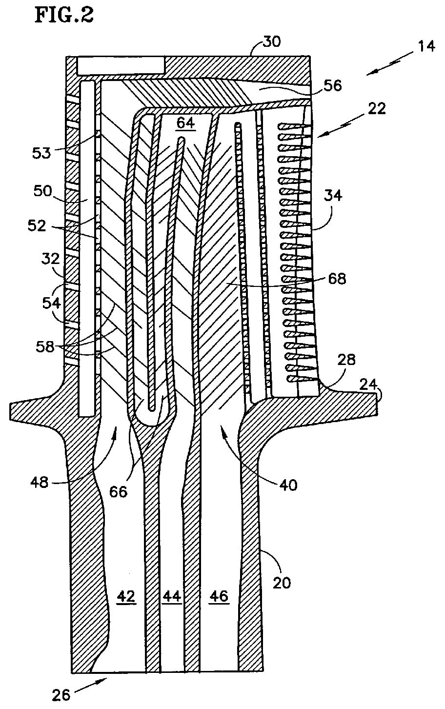
- FIG. 2 diagrammatically illustrates an airfoil 22 sectioned between the leading edge 32 and the trailing edge 34.
- the pressure side wall 36 and the suction side wall 38 extend between the base 28 and the tip 30 and meet at the leading edge 32 and the trailing edge 34.
- the internal passage configuration includes a first conduit 42, a second conduit 44, and a third conduit 46 extending through the root 20 into the airfoil 22. Fewer or more conduits may be used alternatively.
- the first conduit 42 is in fluid communication with a first radial passage 48.
- a second radial passage 50 is disposed forward of the first radial passage 48, contiguous with the leading edge 32, and is connected to the first radial passage 48 by a plurality of crossover apertures 52.
- the crossover apertures 52 are disposed in a rib 53 that extends between and separates the first radial passage 48 and the second radial passage 50.
- the second radial passage 50 is connected to the exterior of the airfoil 22 by a plurality of cooling apertures 54 disposed along the leading edge 32.
- the second radial passage 50 comprises one or more cavities. In other embodiments, the second radial passage 50 may be in direct fluid communication with the first conduit 42. At the outer radial end of the first radial passage 48 (i.e., the end of the first radial passage 48 opposite the first conduit 42), the first radial passage 48 is connected to an axially extending passage 56 that extends to the trailing edge 34 of the airfoil 22, adjacent the tip 30 of the airfoil 22.
- a portion of the crossover apertures 52 disposed in the rib 53 are oblong, each having a length 70, width 72, and height 74. In a preferred embodiment, substantially all of the crossover apertures 52 are oblong.
- the length 70 of each crossover aperture 52 extends through the rib 53.
- the height 74 and width 72 are substantially perpendicular to each other and to the length 70.
- the height 74 of each oblong crossover aperture 52 is greater than the width 72. In a preferred embodiment, the height 74 is approximately twice the width 72 in magnitude.
- the oblong crossover apertures 52 are aligned heightwise along the rib 53, such that the heights 74 of the oblong crossover apertures 52 are substantially collinear. In the embodiment shown in FIGS. 3 and 4, the oblong crossover apertures 52 are shown as having a constant width 72 and circular ends. The oblong crossover apertures 52 are not limited to this embodiment.
- the rib 53 is separated from the interior surface of the leading edge wall 78 by a distance "L".
- the oblong crossover apertures 52 may be described as having a hydraulic diameter "D".
- the separation of the rib 53 from the leading edge wall 78, and the size of the oblong crossover apertures 53 are such that the ratio of L/D is on average in the approximate range of 2.8 to 3.0. It is our experience that an L/D in this approximate range provides desirable impingement cooling.
- the first radial passage 48 includes a plurality of trip strips 58 attached to the interior surface of one or both of the pressure side wall 36 and the suction side wall 38.
- the trip strips 58 are disposed within the passage 48 at an angle ⁇ that is skewed relative to the cooling airflow direction 60 within passage 48; i.e., at an angle between perpendicular and parallel to the airflow direction 60.
- the trip strips 58 are oriented at angle of approximately 45° to the cooling airflow direction 60.
- the orientation of each trip strip 58 within the passage 48 is such that the trip strip 58 converges toward the rib 53 containing the crossover apertures 52, when viewed in the airflow direction 60.
- Each of the trip strips 58 has an end disposed adjacent the rib 53 (i.e., a "rib end"). At least a portion of the trip strips 58 have a rib end radially located between a pair of crossover apertures 52, preferably approximately midway between the pair of crossover apertures 52.
- the second conduit 44 is in fluid communication with a serpentine passage 64 disposed immediately aft of the first and second radial passages 50, 48, in the mid-body region of the airfoil 22.
- the serpentine passage 64 has an odd number of radial segments 66, which number is greater than one; e.g., 3, 5, etc.
- the odd number of radial segments 66 ensures that the last radial segment in the serpentine 64 ends adjacent the axially extending passage 56.
- Passage configurations other than the aforesaid serpentine passage 64 may be used within the mid-body region alternatively.
- the third conduit 46 is in fluid communication with one or more passages 68 disposed between the serpentine passage 64 and the trailing edge 34 of the airfoil 22.
- the rotor blade airfoil 22 is disposed within the core gas path of the turbine engine.
- the airfoil 22 is subject to high temperature core gas passing by the airfoil 22. Cooling air, that is substantially lower in temperature than the core gas, is fed into the airfoil 22 through the conduits 42, 44, 46 disposed in the root 20.
- Cooling air traveling through the first conduit 42 passes directly into the first radial passage 48, and subsequently into the axially extending passage 56 adjacent the tip 30 of the airfoil 22.
- a portion of the cooling air traveling within the first radial passage 48 encounters the trip strips 58 disposed within the passage 48.
- the trip strips 58 converging toward the rib 53 direct the portion of cooling airflow toward the rib 53.
- the position of the trip strips 58 relative to the crossover apertures 52 are such that the portion of cooling airflow directed toward the rib 53 is also directed toward the crossover apertures 52.
- the portion of cooling airflow travels through the crossover apertures 52 and into the second radial passage 50.
- the cooling air subsequently exits the second radial passage 50 via the cooling apertures 52 disposed in the leading edge 32 and impinges on the interior surface of the leading edge wall.
- prior art circular crossover apertures typically create a line of discrete regions of high heat transfer separated by larger areas of relatively low heat transfer.
- the oblong crossover apertures 52 of the present invention provide a more uniform radial heat transfer profile along the leading edge 32 that the aforesaid prior art.
- the regions of desirable relatively high heat transfer are larger, and the regions of undesirable relatively low heat transfer are smaller.
- the heat transfer within the regions of relatively low heat transfer appears to be increased by cooling air showering radially outward from the oblong crossover apertures 52.
Landscapes
- Engineering & Computer Science (AREA)
- Mechanical Engineering (AREA)
- General Engineering & Computer Science (AREA)
- Turbine Rotor Nozzle Sealing (AREA)
Abstract
Description
Claims (6)
- A rotor blade (14), comprising:a hollow airfoil (22) having a cavity defined by a suction side wall (38), a pressure side wall (36), a leading edge (32), a trailing edge (34), a base (28), and a tip (30);an internal passage configuration (40)disposed within the cavity, which configuration includes a first radial passage (48), a second radial passage (50), a rib (53) disposed between and separating the first radial passage (48) and second radial passage (50), and a plurality of crossover apertures (52) disposed within the rib (53), wherein a portion of the plurality of crossover apertures (52) are oblong having a length (70) extending through the rib (53), and a height (74) and a width (72), and wherein the height (74) of each oblong crossover aperture (52) is greater than the width (72);a root having a conduit (42) that is operable to permit airflow through the root and into the first radial passage (48).
- The rotor blade of claim 1, wherein substantially all of the crossover apertures (52) are oblong.
- The rotor blade of claim 2, wherein the height (74) of each crossover aperture (52) is approximately twice the magnitude of the width (72) of that crossover aperture (52).
- The rotor blade of any preceding claim, wherein the oblong crossover apertures (52) are aligned heightwise along the rib (53).
- The rotor blade of any preceding claim, wherein the second radial passage (50) is contiguous with the leading edge (32).
- The rotor blade of any preceding claim, wherein the rib (53) is separated from the leading edge (32) by a distance "L", and the oblong crossover apertures (52) have a hydraulic diameter "D", and the ratio of L/D is on average in the approximate range of 2.8 to 3.0.
Applications Claiming Priority (2)
| Application Number | Priority Date | Filing Date | Title |
|---|---|---|---|
| US855076 | 1992-03-23 | ||
| US10/855,076 US20050265840A1 (en) | 2004-05-27 | 2004-05-27 | Cooled rotor blade with leading edge impingement cooling |
Publications (3)
| Publication Number | Publication Date |
|---|---|
| EP1605138A2 true EP1605138A2 (en) | 2005-12-14 |
| EP1605138A3 EP1605138A3 (en) | 2007-10-03 |
| EP1605138B1 EP1605138B1 (en) | 2010-06-30 |
Family
ID=34941473
Family Applications (1)
| Application Number | Title | Priority Date | Filing Date |
|---|---|---|---|
| EP05253261A Ceased EP1605138B1 (en) | 2004-05-27 | 2005-05-27 | Cooled rotor blade with leading edge impingement cooling |
Country Status (4)
| Country | Link |
|---|---|
| US (1) | US20050265840A1 (en) |
| EP (1) | EP1605138B1 (en) |
| JP (1) | JP2005337257A (en) |
| DE (1) | DE602005022018D1 (en) |
Cited By (4)
| Publication number | Priority date | Publication date | Assignee | Title |
|---|---|---|---|---|
| FR2918105A1 (en) * | 2007-06-27 | 2009-01-02 | Snecma Sa | Turbine blade for aircraft, has air passage holes with impact distance along directing line, where distance is evolutionary in radial direction of blade to adapt cooling intensity at point of impact of fresh air on leading edge |
| JP2015511678A (en) * | 2012-03-22 | 2015-04-20 | アルストム テクノロジー リミテッドALSTOM Technology Ltd | Turbine blade |
| EP2604800A3 (en) * | 2011-12-15 | 2015-07-22 | General Electric Company | Nozzle vane for a gas turbine engine |
| WO2020242675A1 (en) * | 2019-05-30 | 2020-12-03 | Solar Turbines Incorporated | Turbine blade with serpentine channels |
Families Citing this family (9)
| Publication number | Priority date | Publication date | Assignee | Title |
|---|---|---|---|---|
| US7217094B2 (en) * | 2004-10-18 | 2007-05-15 | United Technologies Corporation | Airfoil with large fillet and micro-circuit cooling |
| US8840370B2 (en) | 2011-11-04 | 2014-09-23 | General Electric Company | Bucket assembly for turbine system |
| JP2013100765A (en) * | 2011-11-08 | 2013-05-23 | Ihi Corp | Impingement cooling mechanism, turbine blade, and combustor |
| US9279331B2 (en) | 2012-04-23 | 2016-03-08 | United Technologies Corporation | Gas turbine engine airfoil with dirt purge feature and core for making same |
| JP5567180B1 (en) * | 2013-05-20 | 2014-08-06 | 川崎重工業株式会社 | Turbine blade cooling structure |
| US10012090B2 (en) * | 2014-07-25 | 2018-07-03 | United Technologies Corporation | Airfoil cooling apparatus |
| CN107109949A (en) * | 2014-11-11 | 2017-08-29 | 西门子公司 | Turbo blade with axial leaf top cooling circuit |
| KR101906701B1 (en) * | 2017-01-03 | 2018-10-10 | 두산중공업 주식회사 | Gas turbine blade |
| US10787932B2 (en) * | 2018-07-13 | 2020-09-29 | Honeywell International Inc. | Turbine blade with dust tolerant cooling system |
Family Cites Families (10)
| Publication number | Priority date | Publication date | Assignee | Title |
|---|---|---|---|---|
| US3619082A (en) * | 1968-07-05 | 1971-11-09 | Gen Motors Corp | Turbine blade |
| US3767322A (en) * | 1971-07-30 | 1973-10-23 | Westinghouse Electric Corp | Internal cooling for turbine vanes |
| US5387086A (en) * | 1993-07-19 | 1995-02-07 | General Electric Company | Gas turbine blade with improved cooling |
| US5688104A (en) * | 1993-11-24 | 1997-11-18 | United Technologies Corporation | Airfoil having expanded wall portions to accommodate film cooling holes |
| JP2000265802A (en) * | 1999-01-25 | 2000-09-26 | General Electric Co <Ge> | Gas turbine blade cooling passage connection |
| US6174134B1 (en) * | 1999-03-05 | 2001-01-16 | General Electric Company | Multiple impingement airfoil cooling |
| US6290463B1 (en) * | 1999-09-30 | 2001-09-18 | General Electric Company | Slotted impingement cooling of airfoil leading edge |
| EP1213442B1 (en) * | 2000-12-05 | 2009-03-11 | United Technologies Corporation | Rotor blade |
| FR2829174B1 (en) * | 2001-08-28 | 2006-01-20 | Snecma Moteurs | IMPROVEMENTS IN COOLING CIRCUITS FOR GAS TURBINE BLADE |
| DE10332563A1 (en) * | 2003-07-11 | 2005-01-27 | Rolls-Royce Deutschland Ltd & Co Kg | Turbine blade with impingement cooling |
-
2004
- 2004-05-27 US US10/855,076 patent/US20050265840A1/en not_active Abandoned
-
2005
- 2005-05-27 EP EP05253261A patent/EP1605138B1/en not_active Ceased
- 2005-05-27 DE DE602005022018T patent/DE602005022018D1/en not_active Expired - Lifetime
- 2005-05-27 JP JP2005154978A patent/JP2005337257A/en active Pending
Cited By (9)
| Publication number | Priority date | Publication date | Assignee | Title |
|---|---|---|---|---|
| FR2918105A1 (en) * | 2007-06-27 | 2009-01-02 | Snecma Sa | Turbine blade for aircraft, has air passage holes with impact distance along directing line, where distance is evolutionary in radial direction of blade to adapt cooling intensity at point of impact of fresh air on leading edge |
| EP2604800A3 (en) * | 2011-12-15 | 2015-07-22 | General Electric Company | Nozzle vane for a gas turbine engine |
| US9151173B2 (en) | 2011-12-15 | 2015-10-06 | General Electric Company | Use of multi-faceted impingement openings for increasing heat transfer characteristics on gas turbine components |
| JP2015511678A (en) * | 2012-03-22 | 2015-04-20 | アルストム テクノロジー リミテッドALSTOM Technology Ltd | Turbine blade |
| US9932836B2 (en) | 2012-03-22 | 2018-04-03 | Ansaldo Energia Ip Uk Limited | Turbine blade |
| WO2020242675A1 (en) * | 2019-05-30 | 2020-12-03 | Solar Turbines Incorporated | Turbine blade with serpentine channels |
| US10895168B2 (en) | 2019-05-30 | 2021-01-19 | Solar Turbines Incorporated | Turbine blade with serpentine channels |
| CN113874600A (en) * | 2019-05-30 | 2021-12-31 | 索拉透平公司 | Turbine blades with serpentine channels |
| CN113874600B (en) * | 2019-05-30 | 2023-06-27 | 索拉透平公司 | Turbine blades with serpentine channels |
Also Published As
| Publication number | Publication date |
|---|---|
| DE602005022018D1 (en) | 2010-08-12 |
| US20050265840A1 (en) | 2005-12-01 |
| JP2005337257A (en) | 2005-12-08 |
| EP1605138A3 (en) | 2007-10-03 |
| EP1605138B1 (en) | 2010-06-30 |
Similar Documents
| Publication | Publication Date | Title |
|---|---|---|
| US7195448B2 (en) | Cooled rotor blade | |
| US6616406B2 (en) | Airfoil trailing edge cooling construction | |
| CN103104300B (en) | film hole trench | |
| CN101191424B (en) | Turbine blade and turbine blade cooling system and methods | |
| CN103080477B (en) | Gas-turbine blade | |
| EP1600604B1 (en) | Cooler rotor blade and method for cooling a rotor blade | |
| EP1605138B1 (en) | Cooled rotor blade with leading edge impingement cooling | |
| US20120070307A1 (en) | Turbine blades, turbine assemblies, and methods of manufacturing turbine blades | |
| CN101960097A (en) | Turbine blade and corresponding turbine and turbo machine with most advanced and sophisticated cooling | |
| US10465524B2 (en) | Turbine blade | |
| US7665968B2 (en) | Cooled rotor blade | |
| US20200291801A1 (en) | Turbine engine airfoil and method | |
| US20130084191A1 (en) | Turbine blade with impingement cavity cooling including pin fins | |
| EP3177811B1 (en) | Gas turbine engine compressor | |
| US7059825B2 (en) | Cooled rotor blade | |
| EP1605136B1 (en) | Cooled rotor blade | |
| EP2639405B1 (en) | Turbine blade tip cooling | |
| EP2752554A1 (en) | Blade for a turbomachine | |
| EP2562353A2 (en) | Axially cooled airfoil | |
| US5507621A (en) | Cooling air cooled gas turbine aerofoil | |
| US20130236329A1 (en) | Rotor blade with one or more side wall cooling circuits | |
| JP2001164902A (en) | Hollow airfoil | |
| RU2575842C2 (en) | Gas turbine blade | |
| EP3109404A1 (en) | Turbine assembly |
Legal Events
| Date | Code | Title | Description |
|---|---|---|---|
| PUAI | Public reference made under article 153(3) epc to a published international application that has entered the european phase |
Free format text: ORIGINAL CODE: 0009012 |
|
| AK | Designated contracting states |
Kind code of ref document: A2 Designated state(s): AT BE BG CH CY CZ DE DK EE ES FI FR GB GR HU IE IS IT LI LT LU MC NL PL PT RO SE SI SK TR |
|
| AX | Request for extension of the european patent |
Extension state: AL BA HR LV MK YU |
|
| PUAL | Search report despatched |
Free format text: ORIGINAL CODE: 0009013 |
|
| AK | Designated contracting states |
Kind code of ref document: A3 Designated state(s): AT BE BG CH CY CZ DE DK EE ES FI FR GB GR HU IE IS IT LI LT LU MC NL PL PT RO SE SI SK TR |
|
| AX | Request for extension of the european patent |
Extension state: AL BA HR LV MK YU |
|
| 17P | Request for examination filed |
Effective date: 20080111 |
|
| 17Q | First examination report despatched |
Effective date: 20080222 |
|
| AKX | Designation fees paid |
Designated state(s): DE GB |
|
| GRAP | Despatch of communication of intention to grant a patent |
Free format text: ORIGINAL CODE: EPIDOSNIGR1 |
|
| GRAS | Grant fee paid |
Free format text: ORIGINAL CODE: EPIDOSNIGR3 |
|
| GRAA | (expected) grant |
Free format text: ORIGINAL CODE: 0009210 |
|
| AK | Designated contracting states |
Kind code of ref document: B1 Designated state(s): DE GB |
|
| REG | Reference to a national code |
Ref country code: GB Ref legal event code: FG4D |
|
| REF | Corresponds to: |
Ref document number: 602005022018 Country of ref document: DE Date of ref document: 20100812 Kind code of ref document: P |
|
| PLBE | No opposition filed within time limit |
Free format text: ORIGINAL CODE: 0009261 |
|
| STAA | Information on the status of an ep patent application or granted ep patent |
Free format text: STATUS: NO OPPOSITION FILED WITHIN TIME LIMIT |
|
| 26N | No opposition filed |
Effective date: 20110331 |
|
| REG | Reference to a national code |
Ref country code: DE Ref legal event code: R097 Ref document number: 602005022018 Country of ref document: DE Effective date: 20110330 |
|
| REG | Reference to a national code |
Ref country code: DE Ref legal event code: R082 Ref document number: 602005022018 Country of ref document: DE Representative=s name: SCHMITT-NILSON SCHRAUD WAIBEL WOHLFROM PATENTA, DE |
|
| REG | Reference to a national code |
Ref country code: DE Ref legal event code: R082 Ref document number: 602005022018 Country of ref document: DE Representative=s name: SCHMITT-NILSON SCHRAUD WAIBEL WOHLFROM PATENTA, DE Ref country code: DE Ref legal event code: R081 Ref document number: 602005022018 Country of ref document: DE Owner name: UNITED TECHNOLOGIES CORP. (N.D.GES.D. STAATES , US Free format text: FORMER OWNER: UNITED TECHNOLOGIES CORP., HARTFORD, CONN., US |
|
| PGFP | Annual fee paid to national office [announced via postgrant information from national office to epo] |
Ref country code: DE Payment date: 20190418 Year of fee payment: 15 |
|
| REG | Reference to a national code |
Ref country code: DE Ref legal event code: R119 Ref document number: 602005022018 Country of ref document: DE |
|
| PG25 | Lapsed in a contracting state [announced via postgrant information from national office to epo] |
Ref country code: DE Free format text: LAPSE BECAUSE OF NON-PAYMENT OF DUE FEES Effective date: 20201201 |
|
| PGFP | Annual fee paid to national office [announced via postgrant information from national office to epo] |
Ref country code: GB Payment date: 20230420 Year of fee payment: 19 |
|
| GBPC | Gb: european patent ceased through non-payment of renewal fee |
Effective date: 20240527 |
|
| PG25 | Lapsed in a contracting state [announced via postgrant information from national office to epo] |
Ref country code: GB Free format text: LAPSE BECAUSE OF NON-PAYMENT OF DUE FEES Effective date: 20240527 |