EP1604864A2 - Ramp for loading vehicles - Google Patents
Ramp for loading vehicles Download PDFInfo
- Publication number
- EP1604864A2 EP1604864A2 EP05012511A EP05012511A EP1604864A2 EP 1604864 A2 EP1604864 A2 EP 1604864A2 EP 05012511 A EP05012511 A EP 05012511A EP 05012511 A EP05012511 A EP 05012511A EP 1604864 A2 EP1604864 A2 EP 1604864A2
- Authority
- EP
- European Patent Office
- Prior art keywords
- vehicles
- ramp
- crosspieces
- ramps
- transverse
- Prior art date
- Legal status (The legal status is an assumption and is not a legal conclusion. Google has not performed a legal analysis and makes no representation as to the accuracy of the status listed.)
- Withdrawn
Links
Images


Classifications
-
- B—PERFORMING OPERATIONS; TRANSPORTING
- B60—VEHICLES IN GENERAL
- B60P—VEHICLES ADAPTED FOR LOAD TRANSPORTATION OR TO TRANSPORT, TO CARRY, OR TO COMPRISE SPECIAL LOADS OR OBJECTS
- B60P1/00—Vehicles predominantly for transporting loads and modified to facilitate loading, consolidating the load, or unloading
- B60P1/43—Vehicles predominantly for transporting loads and modified to facilitate loading, consolidating the load, or unloading using a loading ramp mounted on the vehicle
-
- B—PERFORMING OPERATIONS; TRANSPORTING
- B65—CONVEYING; PACKING; STORING; HANDLING THIN OR FILAMENTARY MATERIAL
- B65G—TRANSPORT OR STORAGE DEVICES, e.g. CONVEYORS FOR LOADING OR TIPPING, SHOP CONVEYOR SYSTEMS OR PNEUMATIC TUBE CONVEYORS
- B65G69/00—Auxiliary measures taken, or devices used, in connection with loading or unloading
- B65G69/28—Loading ramps; Loading docks
- B65G69/30—Non-permanently installed loading ramps, e.g. transportable
-
- B—PERFORMING OPERATIONS; TRANSPORTING
- B66—HOISTING; LIFTING; HAULING
- B66F—HOISTING, LIFTING, HAULING OR PUSHING, NOT OTHERWISE PROVIDED FOR, e.g. DEVICES WHICH APPLY A LIFTING OR PUSHING FORCE DIRECTLY TO THE SURFACE OF A LOAD
- B66F7/00—Lifting frames, e.g. for lifting vehicles; Platform lifts
- B66F7/24—Lifting frames, e.g. for lifting vehicles; Platform lifts for raising or lowering vehicles by their own power
- B66F7/243—Ramps
Definitions
- the present invention relates to a ramp for vehicles.
- Removable ramps are known that are used for loading different kinds of vehicle, especially vehicles equipped with tracks, onto the loading surfaces of trucks or trailers used to transport them.
- Known ramps comprise an elongated structure composed of a pair of longitudinal members, which constitute its sides, between which crosspieces or plates are fixed that give rise to the running plane of the ramps.
- the ramps are made of light materials, for example aluminium, to enable easier manipulation thereof; furthermore, the structures of the crosspieces are modular and have broken-line cross sections, to create reinforcements suitable for withstanding the flexure due to the weight of the vehicles; the modular design of both the crosspieces and of the longitudinal members enables ramps to be made that have lengths that are adaptable to specific needs and the heights to be ascended and the angle of tilt to be determined that is to be provided for each type of vehicle.
- the known ramps have a first drawback that mainly occurs when the vehicles that drive up them are of the type provided with tracks: when the tracks start the ascent up the ramps fitted between the ground and the threshold of a loading surface, and are thus tilted, the latter, for an initial portion rest exclusively on two end points in which the contact with both the ground and with the ramps occurs, thus concentrating the vehicle's weight on these two points.
- the tracks apply a force of traction in these points that has a direction that is tangential to the contact surfaces, and thus to the running planes of the ramps, a force the reaction of which enables the vehicle to move and ascend along the latter.
- Each actuation of the brakes is transmitted to the ramps through the tracks, loading them in a repetitive manner with great overloading pulses.
- a second drawback is the fact that the ramps form ascent angles of significant degree and for this reason the vehicles may slide down the running plane, both during ascent and descent, thus creating abrasion that causes acceleration of damage to the ramps.
- An object of the present ramp for vehicles is to improve the prior art.
- a further object is to excogitate a ramp for vehicles that enables the ascent and descent of tracked vehicles from the bodies of vehicles designed for their transport without premature structural failures occurring.
- Another object is to devise a ramp for vehicles that improves adhesion of the rectilinear-motion members of the latter to the running plane.
- a ramp for vehicles, comprising a running-surface body provided with reinforcing means characterised in that at least a portion of said body is provided with further reinforcing means.
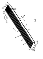
- 1 indicates two ramps for allowing the ascent or descent of a vehicle 2 onto or from a loading surface 4 suitable for the transport of the latter.
- the vehicle 2 is an excavating machine provided with tracks 5.
- Each of the ramps 1 is provided, at an end 101 facing the plane 3, with a respective element 6 joining and connecting the latter and is provided with a respective lip 7 engageable with a bracket 8 projecting from the rear edge of the plane 3, to hook the ramp 1 to the latter.
- each ramp 1 On the side opposite the end 101, in each ramp 1 a second end 201 is defined that is intended to be rested on the ground T and which has a portion T1 that is provided with further reinforcing means 9.
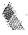
- Each ramp 1 comprises a pair of longitudinal members 10 that are parallel to each other and form the sides thereof and a plurality of crosspieces 11 that are fixed parallel to and contiguously with one another by fixing means 17 and which have a cross section that substantially forms a broken-line profiled element, that is alternatively open and shut.
- the further reinforcing means 9 comprises a series of crosspieces 111 that are still fixed parallel and contiguously to one another by the fixing means 17 and which have a cross section that has a closed perimeter, as shown in the detail in Figure 5.
- the crosspieces 11 and 111 together form a running plane 311 on which the vehicles 2 may travel.
- the ends of the crosspieces 11 and 111 are housed in respective longitudinal guides 12 that are provided on the internal faces of the longitudinal members 10.
- the crosspieces 111 comprise segments of profiled element and the perimeter of the section of the latter defines a first side 13 and a second side 14 that are substantially parallel to one another; the sides 13 and 14 are joined with a respective transverse third side 15 and a respective transverse fourth side 16 and are provided with the aforementioned fixing means 17.
- the latter in its preferred embodiment, respectively comprises a female element 117 that has a T-shaped transverse section and a male element 118 that has the same section and dimensions such as to be able to be slideably inserted into the female element 117 of a contiguous crosspiece 111.
- the third side 15 has two portions 115 tilted and converging towards the fourth side 16 and which form a concavity 18 that faces outwards and defines with the running plane 311, tooth means 113 that also faces outwards and on a side opposite the fourth side 16 and is oriented to promote the ascent and descent of the vehicles 2.
- the length of the portion is determined on an individual basis, according to the type of vehicles for which the ramps 1 are used or can be previously determined in proportion to the wheelbase P of the vehicles that have to climb up or down the ramps 1, the term wheelbase P being defined, as is known, as the distance between two axles M1 and M2 of the vehicles on which the normal wheels are fitted for transfer or the toothed wheels 105 are fitted on which the tracks 5 are closed.
- the portion T1 opposes a mechanical resistance that is noticeably greater than that of known ramps, and the presence of the oriented tooth means 113 enables slipping of the tracks 5 or of normal wheels with pneumatic tyres to be avoided, both during the ascent and descent of vehicles up and down the ramps 1.
- the portion T1 comprises, in the preferred embodiment, a first monobloc profiled end element, indicated by 211, which is composed of a plurality of crosspieces 111 that have a closed-perimeter section, and of a number of further single crosspieces 111 that are fixed together and are interposed between the monobloc profiled element 211 and the crosspieces 11; the number of the single crosspieces 111 is variable and determines the total length of the ramp 1.
- the further reinforcing means (9) comprises a preset number of further crosspieces 111 that have cross sections that have a thickness that is noticeably greater than the thickness of the sections of the crosspieces 1.
- the further crosspieces 111 have solid transverse cross sections.
Landscapes
- Engineering & Computer Science (AREA)
- Mechanical Engineering (AREA)
- Life Sciences & Earth Sciences (AREA)
- Geology (AREA)
- Structural Engineering (AREA)
- Transportation (AREA)
- Auxiliary Methods And Devices For Loading And Unloading (AREA)
- Vehicle Step Arrangements And Article Storage (AREA)
- Body Structure For Vehicles (AREA)
Abstract
Description
Claims (15)
- Ramp (1) for vehicles (2), comprising a running-surface body provided with reinforcing means characterised in that at least a portion of said body is provided with further reinforcing means (9).
- Ramp (1) for vehicles (2) according to claim 1 wherein said body defines a second ground support (T) end (201) and a first end (101) opposite said second end (201), positionable during use at a greater height than said second end (201).
- Ramp (1) for vehicles (2) according to any one of claims 1 or 2 wherein said second end (201) has a portion (T1) of said body comprising said second end (201) that is provided with said further reinforcing means (9).
- Ramp (1) for vehicles (2) according to claim 1 wherein said body comprises:a plurality of crosspieces (11) brought up parallel to one another and fixed together transversely to a travel direction that define a running surface (311),containing means (10, 12) of the ends of said crosspieces .
- Ramp (1) for vehicles (2) according to claim 1 or 2 wherein said further reinforcing means (9) comprises a preset number of further crosspieces (111) brought up to one another and parallel to said crosspieces (11), said further crosspieces (111) having transverse closed-perimeter sections.
- Ramp (1) for vehicles (2) according to claim 1 or 2 wherein said further reinforcing means (9) comprises a preset number of further crosspieces (111) that have cross sections having significantly greater thicknesses than the thickness of the sections of said crosspieces (11).
- Ramp (1) for vehicles (2) according to claim 1 or 2 wherein said preset number of said further crosspieces (111) has solid cross sections.
- Ramp (1) for vehicles (2) according to any one of claims 1 to 7 wherein said cross sections of at least said further crosspieces (111) form longitudinal raised tooth means (113).
- Ramp (1) for vehicles (2) according to claim 8 wherein said tooth means (113) is orientated to promote the ascent of the vehicles (2) onto said ramp (1).
- Ramp (1) for vehicles (2) according to any one of claims 1 to 9 wherein said portion (T1) has a length that is proportionate to the wheelbase (P) of the vehicles (2).
- Ramp (1) for vehicles (2) according to any one of claims 1 to 10 wherein said portion (T1) comprises a monobloc element (211) and a presettable number of further crosspieces (111), for the presetting of the length of said ramp (1).
- Crosspiece (111) for ramps (1) for vehicles (2) characterised in that it has a closed-perimeter box transverse section that defines a first side (13) and a second side (14) that are substantially parallel to one another and are transversely orthogonal to a running plane (311), said first side (13) and second side (14) being joined to a respective transverse third side (15) and a transverse fourth side (16), contiguous crosspiece (111) joining means being provided that is placed on said first side (13) and second side (14).
- Crosspiece (111) according to claim 12 wherein said third transverse side (15) has two converging portions (115) tilted to said fourth side (16) and forming a concavity (18) that generates tooth means (113) facing outwardly and opposite said fourth side (16).
- Crosspiece (111) according to claim 12 wherein said fixing means (17) comprises male elements (118) and female elements (117) couplable with corresponding female elements (117) and male elements (118) of contiguous crosspieces (111).
- Use of a profiled element for crosspieces (111) according to any one of claims from 11 to 14 for the formation of running bodies of ramps (1) for vehicles (2).
Applications Claiming Priority (2)
| Application Number | Priority Date | Filing Date | Title |
|---|---|---|---|
| ITMO20040147 | 2004-06-11 | ||
| ITMO20040147 ITMO20040147A1 (en) | 2004-06-11 | 2004-06-11 | RAMP FOR VEHICLES |
Publications (2)
| Publication Number | Publication Date |
|---|---|
| EP1604864A2 true EP1604864A2 (en) | 2005-12-14 |
| EP1604864A3 EP1604864A3 (en) | 2006-02-15 |
Family
ID=34937364
Family Applications (1)
| Application Number | Title | Priority Date | Filing Date |
|---|---|---|---|
| EP05012511A Withdrawn EP1604864A3 (en) | 2004-06-11 | 2005-06-10 | Ramp for loading vehicles |
Country Status (2)
| Country | Link |
|---|---|
| EP (1) | EP1604864A3 (en) |
| IT (1) | ITMO20040147A1 (en) |
Cited By (1)
| Publication number | Priority date | Publication date | Assignee | Title |
|---|---|---|---|---|
| WO2011051522A3 (en) * | 2009-10-06 | 2011-08-11 | Gueell Perpinya Francisco Javier | Clip-assembled, weld-free folding or fixed ramp for overcoming changes in level |
Family Cites Families (5)
| Publication number | Priority date | Publication date | Assignee | Title |
|---|---|---|---|---|
| US4042992A (en) * | 1976-08-30 | 1977-08-23 | Herbert Management Co., Inc. | Portable reinforced loading ramp |
| GB2088821A (en) * | 1980-12-05 | 1982-06-16 | Healy Richard | Car ramp |
| FR2611682B1 (en) * | 1987-03-06 | 1992-01-24 | Lefevre Pierre | MOVABLE SUPPORT OR GATEWAY FOR BRINGING A VEHICLE INTO THE RAISED POSITION |
| US5446937A (en) * | 1992-09-08 | 1995-09-05 | Pemko Manufacturing Company | Modular ramp system |
| SE525008C2 (en) * | 2003-03-26 | 2004-11-09 | Carl Keruboeoe Ab | threshold Ramp |
-
2004
- 2004-06-11 IT ITMO20040147 patent/ITMO20040147A1/en unknown
-
2005
- 2005-06-10 EP EP05012511A patent/EP1604864A3/en not_active Withdrawn
Cited By (1)
| Publication number | Priority date | Publication date | Assignee | Title |
|---|---|---|---|---|
| WO2011051522A3 (en) * | 2009-10-06 | 2011-08-11 | Gueell Perpinya Francisco Javier | Clip-assembled, weld-free folding or fixed ramp for overcoming changes in level |
Also Published As
| Publication number | Publication date |
|---|---|
| ITMO20040147A1 (en) | 2004-09-11 |
| EP1604864A3 (en) | 2006-02-15 |
Similar Documents
| Publication | Publication Date | Title |
|---|---|---|
| USRE34889E (en) | Vehicle service ramp | |
| US6880194B2 (en) | Portable ramp assembly | |
| US5845356A (en) | Loading ramp and handling apparatus | |
| EP2796395B1 (en) | Device for the blocking of the wheel of a truck at a positioning place near a facade with a loading and unloading platform | |
| US20210316974A1 (en) | Vehicle Leveler with Wheel Chock | |
| CA2626241A1 (en) | Auto-rack railroad car vehicle wheel chock | |
| CA2913053A1 (en) | Low floor vehicles for transporting passengers | |
| WO2007071831A1 (en) | Transfer plate and method for loading a cargo space | |
| US4154348A (en) | Side-loading transport of automobiles by rail | |
| CA3194624C (en) | Wheel chock with longitudinal extension | |
| NL8103294A (en) | DEVICE FOR STOPPING CARGO. | |
| US4237794A (en) | Automobile securement mechanism to freight car | |
| EP1604864A2 (en) | Ramp for loading vehicles | |
| EP0870706B1 (en) | Loading floor of a commercial vehicle with loading ramp(s) | |
| US20200214914A1 (en) | A vehicular lift | |
| CA3127263C (en) | Vehicle leveler with wheel chock | |
| US20250296496A1 (en) | Auto slide | |
| RU241721U1 (en) | Truck restraint device | |
| CA2890811C (en) | Traction device | |
| US11753261B2 (en) | Vehicle leveler with safety features | |
| CN216271618U (en) | Conveying device for assembly and carrying assembly line of vehicle parts | |
| DE29820297U1 (en) | Transfer system for the horizontal transfer of load carriers in the logistics area of freight and passenger transport | |
| GB2644341A (en) | Traction bar, ramp apparatus and haulage vehicle | |
| EP1762514A1 (en) | Loading ramp | |
| CA3115379A1 (en) | Vehicle leveler with safety features |
Legal Events
| Date | Code | Title | Description |
|---|---|---|---|
| PUAI | Public reference made under article 153(3) epc to a published international application that has entered the european phase |
Free format text: ORIGINAL CODE: 0009012 |
|
| AK | Designated contracting states |
Kind code of ref document: A2 Designated state(s): AT BE BG CH CY CZ DE DK EE ES FI FR GB GR HU IE IS IT LI LT LU MC NL PL PT RO SE SI SK TR |
|
| AX | Request for extension of the european patent |
Extension state: AL BA HR LV MK YU |
|
| PUAL | Search report despatched |
Free format text: ORIGINAL CODE: 0009013 |
|
| AK | Designated contracting states |
Kind code of ref document: A3 Designated state(s): AT BE BG CH CY CZ DE DK EE ES FI FR GB GR HU IE IS IT LI LT LU MC NL PL PT RO SE SI SK TR |
|
| AX | Request for extension of the european patent |
Extension state: AL BA HR LV MK YU |
|
| 17P | Request for examination filed |
Effective date: 20060831 |
|
| AKX | Designation fees paid |
Designated state(s): AT BE BG CH CY CZ DE DK EE ES FI FR GB GR HU IE IS IT LI LT LU MC NL PL PT RO SE SI SK TR |
|
| D17P | Request for examination filed (deleted) | ||
| REG | Reference to a national code |
Ref country code: DE Ref legal event code: 8566 |
|
| 17Q | First examination report despatched |
Effective date: 20061214 |
|
| GRAP | Despatch of communication of intention to grant a patent |
Free format text: ORIGINAL CODE: EPIDOSNIGR1 |
|
| STAA | Information on the status of an ep patent application or granted ep patent |
Free format text: STATUS: THE APPLICATION IS DEEMED TO BE WITHDRAWN |
|
| 18D | Application deemed to be withdrawn |
Effective date: 20100615 |