EP1604857A2 - Vehicle and one piece shroud - Google Patents
Vehicle and one piece shroud Download PDFInfo
- Publication number
- EP1604857A2 EP1604857A2 EP05104944A EP05104944A EP1604857A2 EP 1604857 A2 EP1604857 A2 EP 1604857A2 EP 05104944 A EP05104944 A EP 05104944A EP 05104944 A EP05104944 A EP 05104944A EP 1604857 A2 EP1604857 A2 EP 1604857A2
- Authority
- EP
- European Patent Office
- Prior art keywords
- fan shroud
- radiator
- frame
- hood
- seal
- Prior art date
- Legal status (The legal status is an assumption and is not a legal conclusion. Google has not performed a legal analysis and makes no representation as to the accuracy of the status listed.)
- Granted
Links
Images


Classifications
-
- B—PERFORMING OPERATIONS; TRANSPORTING
- B60—VEHICLES IN GENERAL
- B60K—ARRANGEMENT OR MOUNTING OF PROPULSION UNITS OR OF TRANSMISSIONS IN VEHICLES; ARRANGEMENT OR MOUNTING OF PLURAL DIVERSE PRIME-MOVERS IN VEHICLES; AUXILIARY DRIVES FOR VEHICLES; INSTRUMENTATION OR DASHBOARDS FOR VEHICLES; ARRANGEMENTS IN CONNECTION WITH COOLING, AIR INTAKE, GAS EXHAUST OR FUEL SUPPLY OF PROPULSION UNITS IN VEHICLES
- B60K11/00—Arrangement in connection with cooling of propulsion units
- B60K11/02—Arrangement in connection with cooling of propulsion units with liquid cooling
Definitions
- This invention relates generally to internal combustion engine cooling systems, and more particularly to shrouds for fans that force a flow of cooling air through or across the radiator of a utility vehicle such as a tractor.
- Utility vehicles such as tractors with internal combustion engines have engine cooling systems that draw air from a front grill through a radiator into the engine compartment.
- the engine cooling system typically includes a radiator assembly with a cooling fan surrounded by a shroud.
- the cooling fan may be provided to force flow of cooling air across the radiator.
- the radiator may be disposed forwardly of the cooling fan, and the cooling fan may be disposed forwardly of the engine.
- Optimum performance of the engine cooling system requires that air flow be blocked or minimized around the first or engine side of the radiator assembly (i.e., the hot engine compartment) to the second or cool side of the radiator assembly (i.e., the front grill).
- Efforts to seal the engine side from the cool side have involved various combinations of outward extensions from the radiator area, along with sealing materials such as foam or rubber to fill gaps between the radiator assembly and the vehicle hood and/or side panels.
- seals may include foam or rubber material that fills gaps between the internal surface of the vehicle hood and the radiator assembly. Several pieces and/or sizes of sealing material may be needed because the size of the gaps may vary.
- An improved and simplified sealing arrangement is needed between the engine side and cool side of a tractor radiator assembly.
- the radiator assembly includes structural components that support the radiator and fan shroud and/or attach those structures to the frame or body of the vehicle, parts that seal the radiator assembly and air intake passages, and auxiliary items such as coolant recovery bottles.
- a typical radiator package has a large number of parts and requires substantial assembly time, at a significant cost.
- a one piece fan shroud for a tractor has first and second faces, a frame with top, left and right sides, a bottom, and an upper wall extending from the top of the frame.
- the upper wall, left and right sides of the fan shroud are dimensioned to match the internal geometry and seal with an internal surface of a tractor hood.
- a preferably rubber seal may extend around the upper wall and the left and right sides of the frame.
- fan shroud 10 is a one piece structure positioned on and/or over the frame or chassis of a utility vehicle such as a tractor.
- fan shroud 10 is injection molded glass reinforced plastic.
- the fan shroud may be molded or formed from a polymeric material such as glass fiber mineral reinforced, highly chemically coupled polypropylene.
- the fan shroud may have a nominal material wall thickness of between about 2 mm and about 10 mm, and most preferably about 3.5 mm.
- the fan shroud may have ribs 19, 29 to enhance structural integrity or stiffness of the material.
- the fan shroud may be made from sheet metal.
- fan shroud 10 may have a generally rectangular or square frame 20 with four sides: top 12, left and right sides 13a and 13b, and bottom 14.
- frame 20 When fan shroud 10 is positioned on a vehicle such as a tractor, frame 20 is oriented in a generally vertical plane, with a first face 50 facing the radiator, and a second face 51 facing the engine of the vehicle.
- bottom 14 when fan shroud 10 is viewed from the side, such as in the side cross section view of Fig. 2, bottom 14 has a thicker cross section than top 12, giving frame 20 a slightly wedge shape appearance.
- the fan shroud may have a generally cylindrical fan wall 11 projecting from second face 51 of the frame.
- the fan wall may surround a cooling fan (not shown) that rotates on a generally longitudinal axis.
- panels 24, 28 may connect the cylindrical fan wall to frame 20.
- the fan which may be driven by an internal combustion engine, or may be electrically or hydraulically powered, and may have a plurality of blades which rotate to cause air to move through a radiator.
- fan shroud 10 may be fastened to and at least partially supported by the radiator.
- the fan shroud may be fastened to the radiator using a plurality of fasteners through openings 21, 25.
- the radiator may be attached to the frame using pegs and plastic or rubber isolators between the frame and radiator.
- rod 41 may be used to support or stabilize the fan shroud.
- rod 41 may extend from the second face of the fan shroud, and the rod may be connected to bracket 42 attached to engine 43.
- the fan shroud may be fastened directly to the vehicle frame or chassis.
- upper wall 18 extends from top 12 of the frame.
- Upper wall 18 may extend vertically from the top of the frame, or may extend at an angle ⁇ with respect to the generally vertically aligned frame.
- upper wall 18 may be at an angle of between about 10 degrees and about 60 degrees toward the second face, and most preferably about 30 degrees with respect to a vertical plane.
- one or more passages may extend through upper wall 18.
- air intake opening 15 may extend through upper wall 18 to provide air for combustion.
- Air intake opening 15 may have inlet flange 22 extending or projecting outwardly from the cool air side of upper wall 18, and outlet flange 23 extending or projecting outwardly from the engine side of upper wall 18.
- the inlet and outlet flanges may project sufficiently from upper wall 18 to enable connection of air intake ducts or hoses to the flanges.
- each of the inlet and outlet flanges may project at least about one inch from upper wall 18.
- the inlet flange may extend at least partially over the radiator 32.
- the air intake opening may have a generally oblong shape in cross section.
- opening 16 may extend through upper wall 18 for radiator hose 54 to extend there through.
- Fig. 3 shows an embodiment of fan shroud 10 mounted in the front end of a tractor.
- the tractor has a frame 38 and hood 30.
- the hood may be a one piece metal or polymer structure with a top 36, sides 31, and front or grill 37.
- the hood may be hinged, or may slide or lift to open.
- Radiator 32 is mounted to frame 38.
- radiator 32 may have a top tank 44 and a radiator cap 33.
- Upper wall 18 and sides 13a, 13b are dimensioned to match the internal geometry of hood 30.
- small or substantially zero means less than about one inch measured from upper wall 18 and sides 13a, 13b to the top and sides of the closed hood.
- any variation in the clearance should be plus or minus about 0,635 cm (1 ⁇ 2 inch). Because upper wall 18 and sides 13a, 13b match the internal contour of the hood, they may seal with the hood.
- a seal 34 may be provided around the upper wall and sides of the fan shroud. The seal helps reduce or prevent hot air from circulating from the engine to the cool air side of the radiator.
- seal 34 may be a one piece rubber or elastomer bulb seal that seals the perimeter of three surfaces of the fan shroud with the tractor hood when the hood is closed. Seal 34 may be compressed when the hood is closed. Additionally, seal 39 may be provided between the front 37 of the hood and a corresponding surface on or above frame 38.
- the internal or inwardly facing surfaces of the top and sides of hood 30 may have a ledge 35 or other surface that mates with or matches the profile of the upper wall and sides of the fan shroud.
- the ledge or other surface may enhance the seal formed between the fan shroud and tractor hood.
- a rubber or elastomer seal may be on the hood, to form a seal with a mating surface on the top and sides of the fan shroud.
Landscapes
- Engineering & Computer Science (AREA)
- Chemical & Material Sciences (AREA)
- Combustion & Propulsion (AREA)
- Transportation (AREA)
- Mechanical Engineering (AREA)
- Cooling, Air Intake And Gas Exhaust, And Fuel Tank Arrangements In Propulsion Units (AREA)
- Body Structure For Vehicles (AREA)
Abstract
Description
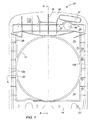
- Fig. 1
- is a rear view of a fan shroud according to a first embodiment of the invention.
- Fig. 2
- is a section view of the fan shroud of Fig. 1, along line A-A.
- Fig. 3
- is a perspective view, partially in section, of a tractor front end with a radiator assembly including a fan shroud according to an embodiment of the invention.
- Fig. 4
- is a partial section view of the top of the fan shroud and tractor hood of Fig. 3.
Claims (9)
- A vehicle, preferably a tractor, having a frame (38), a radiator (32) located on a front of the frame (38), a hood (30) attached to the front of the frame and having internal top, left and right sides, and a one piece fan shroud (10) attached to the radiator (32), characterized in that the one piece fan shroud (10) has three surfaces that seal with the internal top, left and right sides of the hood (30).
- The vehicle according to claim 1, characterized in that the one piece fan shroud (10) has a seal (34) around the three surfaces thereof, the seal (34) preferably being made from rubber and/or being a bulb seal.
- The vehicle according to claim 1 or 2, characterized in that the one piece fan shroud (10) is oriented in a generally vertical alignment, and further comprising an upper wall (18) extending from the fan shroud (10) at an angle of between about 10 degrees and 60 degrees from the generally vertical alignment of the fan shroud (10).
- The vehicle according to one or several of the previous claims, further comprising a ledge (35) around the internal top, left and right sides of the hood (30).
- The vehicle according to one or several of the previous claims, further comprising an air intake passage through the fan shroud (10), the air intake passage preferably having a flange extending at least partially over the radiator (32).
- The vehicle according to one or several of the previous claims, characterized in that the fan shroud (10) is injection molded glass reinforced plastic.
- The vehicle according to one or several of the previous claims, characterized in that the fan wall (11) is generally cylindrical.
- The vehicle according to one or several of the previous claims, characterized in that the radiator (32) is mounted on the frame (38) on the front end of the vehicle having a hinged hood (30), the seal (34) mating with the internal surfaces of the hinged hood (30).
- A one piece shroud (10) of a vehicle according to one or several of the previous claims.
Applications Claiming Priority (2)
| Application Number | Priority Date | Filing Date | Title |
|---|---|---|---|
| US866289 | 2001-05-25 | ||
| US10/866,289 US7418994B2 (en) | 2004-06-11 | 2004-06-11 | Fan shroud with integral hood seal |
Publications (3)
| Publication Number | Publication Date |
|---|---|
| EP1604857A2 true EP1604857A2 (en) | 2005-12-14 |
| EP1604857A3 EP1604857A3 (en) | 2007-05-16 |
| EP1604857B1 EP1604857B1 (en) | 2010-12-08 |
Family
ID=34940098
Family Applications (1)
| Application Number | Title | Priority Date | Filing Date |
|---|---|---|---|
| EP05104944A Ceased EP1604857B1 (en) | 2004-06-11 | 2005-06-07 | Vehicle and one piece shroud |
Country Status (3)
| Country | Link |
|---|---|
| US (1) | US7418994B2 (en) |
| EP (1) | EP1604857B1 (en) |
| DE (1) | DE602005025173D1 (en) |
Cited By (5)
| Publication number | Priority date | Publication date | Assignee | Title |
|---|---|---|---|---|
| WO2010026353A1 (en) | 2008-09-08 | 2010-03-11 | Renault S.A.S. | Device for attaching a power supply relay housing of a motor-fan system onto a nozzle supporting an automobile motor-fan system |
| JP2014008900A (en) * | 2012-06-29 | 2014-01-20 | Mitsubishi Agricultural Machinery Co Ltd | Work vehicle |
| EP2384954A4 (en) * | 2009-01-09 | 2015-04-08 | Yanmar Co Ltd | Bonnet structure |
| US9561717B2 (en) | 2013-07-19 | 2017-02-07 | Agco International Gmbh | Fan shroud on an agricultural vehicle |
| EP3711996A4 (en) * | 2017-11-15 | 2021-07-21 | Hunan CRRC Times Electric Vehicle Co., Ltd | COOLING SYSTEM AND METHOD FOR ENGINE AND CONTROL UNIT |
Families Citing this family (16)
| Publication number | Priority date | Publication date | Assignee | Title |
|---|---|---|---|---|
| JP4613082B2 (en) * | 2005-03-14 | 2011-01-12 | ヤンマー株式会社 | Bonnet structure of work vehicle |
| DE102005039090A1 (en) * | 2005-08-06 | 2007-02-08 | Behr Gmbh & Co. Kg | Assembly support system |
| JP4578410B2 (en) * | 2006-01-16 | 2010-11-10 | ヤンマー株式会社 | Work vehicle front guard |
| US20080047504A1 (en) * | 2006-08-02 | 2008-02-28 | Guido Benvenuto | Fan shroud ring and method for its manufacture |
| US8925510B2 (en) * | 2008-12-17 | 2015-01-06 | Ford Global Technologies, Llc | Automotive air induction system |
| US8403089B2 (en) * | 2008-12-23 | 2013-03-26 | Deere & Company | Use of fan shroud to ventilate engine compartment |
| JP2011073537A (en) * | 2009-09-30 | 2011-04-14 | Honda Motor Co Ltd | Shroud structure of cooling device |
| US8276699B2 (en) * | 2010-09-30 | 2012-10-02 | Deere & Company | Mounting arrangement for tractor front grille to shroud |
| US8893834B2 (en) * | 2011-09-23 | 2014-11-25 | Caterpillar Inc. | Airflow baffle system for articulating hood with multiple hinge locations |
| US8783400B2 (en) * | 2012-06-06 | 2014-07-22 | Honda Motor Co., Ltd. | Fan cover structure for a radiator assembly |
| US9303715B2 (en) | 2013-03-10 | 2016-04-05 | Oshkosh Defense, Llc | Limiting system for a vehicle suspension component |
| US10414266B1 (en) * | 2017-04-28 | 2019-09-17 | Oshkosh Defense, Llc | Vehicle cooling systems and methods |
| US12491943B1 (en) | 2013-03-10 | 2025-12-09 | Oshkosh Defense, Llc | Systems and methods for a military vehicle |
| JP7211922B2 (en) * | 2019-09-27 | 2023-01-24 | 株式会社クボタ | work vehicle |
| US11351847B2 (en) | 2020-03-31 | 2022-06-07 | Toyota Motor Engineering & Manufacturing North America, Inc. | Clipless hood seal |
| GB202020277D0 (en) * | 2020-12-21 | 2021-02-03 | Agco Int Gmbh | Utility vehicle cooling fan installation |
Citations (1)
| Publication number | Priority date | Publication date | Assignee | Title |
|---|---|---|---|---|
| US5927390A (en) | 1996-12-13 | 1999-07-27 | Caterpillar Inc. | Radiator arrangement with offset modular cores |
Family Cites Families (15)
| Publication number | Priority date | Publication date | Assignee | Title |
|---|---|---|---|---|
| US2715448A (en) * | 1952-01-03 | 1955-08-16 | Chrysler Corp | Front sheet metal construction for automotive vehicles |
| US3636684A (en) | 1969-08-25 | 1972-01-25 | Deere & Co | Engine enclosure for a harvesting machine |
| US3987766A (en) | 1975-08-11 | 1976-10-26 | Deere & Company | Engine enclosure and heat deflector arrangement |
| US4018270A (en) | 1975-11-06 | 1977-04-19 | International Harvester Company | Automotive fan shroud for screening debris |
| US4086976A (en) | 1977-02-02 | 1978-05-02 | International Harvester Company | Isolated clean air chamber and engine compartment in a tractor vehicle |
| US4398508A (en) | 1981-02-20 | 1983-08-16 | Volvo White Truck Corporation | Engine cooling fan construction |
| US4454926A (en) | 1982-03-08 | 1984-06-19 | International Harvester Co. | Air intake on a tractor engine hood |
| US4886135A (en) | 1987-05-01 | 1989-12-12 | Kubota, Ltd. | Engine cooling structure for agricultural tractor |
| JPH02196134A (en) * | 1989-01-20 | 1990-08-02 | Mitsubishi Electric Corp | Cooling system for generating set |
| JP2756344B2 (en) * | 1990-04-07 | 1998-05-25 | ヤンマーディーゼル株式会社 | Tractor bonnet mechanism |
| US5427502A (en) | 1994-03-28 | 1995-06-27 | Deere & Company | Fan shroud aspirator |
| DE69713708T2 (en) | 1996-10-22 | 2002-10-17 | Denso Corp., Kariya | Heat exchangers for motor vehicles |
| US6298906B1 (en) | 1997-12-02 | 2001-10-09 | Caterpillar Inc. | Apparatus for securing and sealing a radiator to an engine cowling of a work machine |
| US6883589B2 (en) * | 2000-01-31 | 2005-04-26 | Denso Corporation | Front end structure |
| US20040216934A1 (en) | 2003-01-27 | 2004-11-04 | Kubota Corporation | Working vehicle having a hood |
-
2004
- 2004-06-11 US US10/866,289 patent/US7418994B2/en not_active Expired - Lifetime
-
2005
- 2005-06-07 DE DE602005025173T patent/DE602005025173D1/en not_active Expired - Lifetime
- 2005-06-07 EP EP05104944A patent/EP1604857B1/en not_active Ceased
Patent Citations (1)
| Publication number | Priority date | Publication date | Assignee | Title |
|---|---|---|---|---|
| US5927390A (en) | 1996-12-13 | 1999-07-27 | Caterpillar Inc. | Radiator arrangement with offset modular cores |
Cited By (6)
| Publication number | Priority date | Publication date | Assignee | Title |
|---|---|---|---|---|
| WO2010026353A1 (en) | 2008-09-08 | 2010-03-11 | Renault S.A.S. | Device for attaching a power supply relay housing of a motor-fan system onto a nozzle supporting an automobile motor-fan system |
| FR2935765A1 (en) * | 2008-09-08 | 2010-03-12 | Renault Sas | DEVICE FOR FIXING A POWER SUPPLY RELAY HOUSING OF A MOTORBIKE GROUP ON A NOZZLE SUPPORTING A MOTORBIKE GROUP OF A MOTOR VEHICLE. |
| EP2384954A4 (en) * | 2009-01-09 | 2015-04-08 | Yanmar Co Ltd | Bonnet structure |
| JP2014008900A (en) * | 2012-06-29 | 2014-01-20 | Mitsubishi Agricultural Machinery Co Ltd | Work vehicle |
| US9561717B2 (en) | 2013-07-19 | 2017-02-07 | Agco International Gmbh | Fan shroud on an agricultural vehicle |
| EP3711996A4 (en) * | 2017-11-15 | 2021-07-21 | Hunan CRRC Times Electric Vehicle Co., Ltd | COOLING SYSTEM AND METHOD FOR ENGINE AND CONTROL UNIT |
Also Published As
| Publication number | Publication date |
|---|---|
| US20050274491A1 (en) | 2005-12-15 |
| US7418994B2 (en) | 2008-09-02 |
| EP1604857B1 (en) | 2010-12-08 |
| DE602005025173D1 (en) | 2011-01-20 |
| EP1604857A3 (en) | 2007-05-16 |
Similar Documents
| Publication | Publication Date | Title |
|---|---|---|
| US7418994B2 (en) | Fan shroud with integral hood seal | |
| CN103826896B (en) | For having the air flow baffle system of the hinged cap of multiple hinge position | |
| US7779793B2 (en) | Engine-driven work machine resiliently supported on a frame | |
| US6435264B1 (en) | Cooling system for working vehicle | |
| EP2436547B1 (en) | Mounting arrangement for tractor front grille to shroud | |
| KR950023566A (en) | Bonnet with intake vent for radiator and engine | |
| EP1582715A1 (en) | Vehicle Cooling Package | |
| US6508506B2 (en) | Front end structure of vehicle | |
| US5199522A (en) | Air inlet for vehicle engine | |
| JP2005096684A (en) | Wind guide structure at the front of the body | |
| CN102271989A (en) | Bonnet structure | |
| JP2001213355A (en) | Front end panel | |
| EP1652756B1 (en) | Vehicle Hood | |
| EP2479417B1 (en) | Air cleaner device | |
| US8807113B2 (en) | Device and method for integrating an air cleaner into a radiator fan shroud | |
| JP5805023B2 (en) | Work vehicle | |
| US9914340B1 (en) | Vehicle cowl attachment | |
| US20210254585A1 (en) | Engine air intake device | |
| US11305639B2 (en) | Body structure with integrated air channel | |
| KR102496655B1 (en) | Front end module for electric vehicle | |
| US7370388B2 (en) | Air cleaner for portable engine | |
| CN203612062U (en) | Top cover heat radiation structure and automobile | |
| EP0515737B1 (en) | Air inlet for vehicle engine | |
| JPH02128919A (en) | Tractor bonnet seal structure | |
| US20210340940A1 (en) | Engine air intake device |
Legal Events
| Date | Code | Title | Description |
|---|---|---|---|
| PUAI | Public reference made under article 153(3) epc to a published international application that has entered the european phase |
Free format text: ORIGINAL CODE: 0009012 |
|
| AK | Designated contracting states |
Kind code of ref document: A2 Designated state(s): AT BE BG CH CY CZ DE DK EE ES FI FR GB GR HU IE IS IT LI LT LU MC NL PL PT RO SE SI SK TR |
|
| AX | Request for extension of the european patent |
Extension state: AL BA HR LV MK YU |
|
| PUAL | Search report despatched |
Free format text: ORIGINAL CODE: 0009013 |
|
| AK | Designated contracting states |
Kind code of ref document: A3 Designated state(s): AT BE BG CH CY CZ DE DK EE ES FI FR GB GR HU IE IS IT LI LT LU MC NL PL PT RO SE SI SK TR |
|
| AX | Request for extension of the european patent |
Extension state: AL BA HR LV MK YU |
|
| 17P | Request for examination filed |
Effective date: 20071116 |
|
| AKX | Designation fees paid |
Designated state(s): DE FR GB |
|
| 17Q | First examination report despatched |
Effective date: 20080128 |
|
| GRAP | Despatch of communication of intention to grant a patent |
Free format text: ORIGINAL CODE: EPIDOSNIGR1 |
|
| GRAS | Grant fee paid |
Free format text: ORIGINAL CODE: EPIDOSNIGR3 |
|
| GRAA | (expected) grant |
Free format text: ORIGINAL CODE: 0009210 |
|
| AK | Designated contracting states |
Kind code of ref document: B1 Designated state(s): DE FR GB |
|
| REG | Reference to a national code |
Ref country code: GB Ref legal event code: FG4D |
|
| REF | Corresponds to: |
Ref document number: 602005025173 Country of ref document: DE Date of ref document: 20110120 Kind code of ref document: P |
|
| PLBE | No opposition filed within time limit |
Free format text: ORIGINAL CODE: 0009261 |
|
| STAA | Information on the status of an ep patent application or granted ep patent |
Free format text: STATUS: NO OPPOSITION FILED WITHIN TIME LIMIT |
|
| 26N | No opposition filed |
Effective date: 20110909 |
|
| REG | Reference to a national code |
Ref country code: DE Ref legal event code: R097 Ref document number: 602005025173 Country of ref document: DE Effective date: 20110909 |
|
| REG | Reference to a national code |
Ref country code: FR Ref legal event code: PLFP Year of fee payment: 12 |
|
| REG | Reference to a national code |
Ref country code: FR Ref legal event code: PLFP Year of fee payment: 13 |
|
| PGFP | Annual fee paid to national office [announced via postgrant information from national office to epo] |
Ref country code: CZ Payment date: 20170623 Year of fee payment: 13 |
|
| REG | Reference to a national code |
Ref country code: FR Ref legal event code: PLFP Year of fee payment: 14 |
|
| REG | Reference to a national code |
Ref country code: DE Ref legal event code: R119 Ref document number: 602005025173 Country of ref document: DE |
|
| PG25 | Lapsed in a contracting state [announced via postgrant information from national office to epo] |
Ref country code: DE Free format text: LAPSE BECAUSE OF NON-PAYMENT OF DUE FEES Effective date: 20190101 |
|
| PGFP | Annual fee paid to national office [announced via postgrant information from national office to epo] |
Ref country code: FR Payment date: 20210625 Year of fee payment: 17 |
|
| PGFP | Annual fee paid to national office [announced via postgrant information from national office to epo] |
Ref country code: GB Payment date: 20210628 Year of fee payment: 17 |
|
| GBPC | Gb: european patent ceased through non-payment of renewal fee |
Effective date: 20220607 |
|
| PG25 | Lapsed in a contracting state [announced via postgrant information from national office to epo] |
Ref country code: FR Free format text: LAPSE BECAUSE OF NON-PAYMENT OF DUE FEES Effective date: 20220630 |
|
| PG25 | Lapsed in a contracting state [announced via postgrant information from national office to epo] |
Ref country code: GB Free format text: LAPSE BECAUSE OF NON-PAYMENT OF DUE FEES Effective date: 20220607 |