EP1604607A1 - Biegbarer Abschnitt eines Einführtubus eines Endoskopes und Verfahren zu dessen Herstellung - Google Patents
Biegbarer Abschnitt eines Einführtubus eines Endoskopes und Verfahren zu dessen Herstellung Download PDFInfo
- Publication number
- EP1604607A1 EP1604607A1 EP05011624A EP05011624A EP1604607A1 EP 1604607 A1 EP1604607 A1 EP 1604607A1 EP 05011624 A EP05011624 A EP 05011624A EP 05011624 A EP05011624 A EP 05011624A EP 1604607 A1 EP1604607 A1 EP 1604607A1
- Authority
- EP
- European Patent Office
- Prior art keywords
- bendable
- pipe
- connecting means
- pipe segment
- segments
- Prior art date
- Legal status (The legal status is an assumption and is not a legal conclusion. Google has not performed a legal analysis and makes no representation as to the accuracy of the status listed.)
- Granted
Links
Images


Classifications
-
- A—HUMAN NECESSITIES
- A61—MEDICAL OR VETERINARY SCIENCE; HYGIENE
- A61B—DIAGNOSIS; SURGERY; IDENTIFICATION
- A61B1/00—Instruments for performing medical examinations of the interior of cavities or tubes of the body by visual or photographical inspection, e.g. endoscopes; Illuminating arrangements therefor
- A61B1/005—Flexible endoscopes
- A61B1/0051—Flexible endoscopes with controlled bending of insertion part
- A61B1/0055—Constructional details of insertion parts, e.g. vertebral elements
-
- A—HUMAN NECESSITIES
- A61—MEDICAL OR VETERINARY SCIENCE; HYGIENE
- A61B—DIAGNOSIS; SURGERY; IDENTIFICATION
- A61B1/00—Instruments for performing medical examinations of the interior of cavities or tubes of the body by visual or photographical inspection, e.g. endoscopes; Illuminating arrangements therefor
- A61B1/00064—Constructional details of the endoscope body
- A61B1/0011—Manufacturing of endoscope parts
-
- A—HUMAN NECESSITIES
- A61—MEDICAL OR VETERINARY SCIENCE; HYGIENE
- A61B—DIAGNOSIS; SURGERY; IDENTIFICATION
- A61B1/00—Instruments for performing medical examinations of the interior of cavities or tubes of the body by visual or photographical inspection, e.g. endoscopes; Illuminating arrangements therefor
- A61B1/005—Flexible endoscopes
- A61B1/008—Articulations
Definitions
- the invention relates to a bendable portion which at the distal end of a Insertion tube of an endoscope is arranged, comprising a plurality of tube segments, each of these tube segments having connection means connected to the connection means the adjacent pipe segment cooperate, as well as control cables, with which the Turning the bendable section is controllable, and to a method for producing a such bendable section.
- EP 1 090 581 B1 describes a bendable section which has two control cables has, d. h., The bendable portion is bendable only in one plane, whereas the other the above documents bendable sections with four control trains show that the Turning the bendable section in two planes and consequently a spatial Allow turning.
- All of these known bendable sections consist of a plurality of connecting parts. or joint rings, more generally, of pipe segments, the one above the other Connecting means are mutually pivotally connected to each other, these Connecting means are respectively arranged on the end faces of the pipe segments.
- connection means on the respective end faces of the individual Pipe segments is now dependent on whether the bendable section can only be bent in one plane should be or be spatially, so in two levels bendable. Should the bendable Section only, as shown in EP 1 090 581 B1, be bendable in one plane, then are at each end face, so seen in the distal or in the proximal direction, two in each case Connecting means arranged, these connecting parts by 180 ° in the circumferential direction offset from each other.
- the pivot axes of these connecting means to the individual Pipe segments each extend, viewed in the axial direction, on a continuous Surface line.
- the connecting means are projecting as over the respective end faces of the pipe segments Lugs formed, for example, have holes in which radially ein Hopkins Bolts are inserted. This means that these connecting means, especially the lug-shaped projections, must overlap and therefore to the outside or to are bent inside of the lateral surface of the pipe segments.
- These fasteners like but the bolts arranged therein are then on the outer and / or inner circumference the bendable portion out, but in particular the bolts protrude into the interior of the bendable section into it.
- control cables are guided inside the bendable section, as in DE 42 34 833 A1 and EP 1 090 581 B1, in guides, on the insides individual pipe segments are provided.
- DE 101 43 966 A1 as well as EP 0 439 931 B1 are such guides directly to those in the interior of the bendable section standing bolt heads of the connecting means formed, similar to eyelets.
- the interior of taxpicks form, otherwise the installation of lighting equipment also required, for example Fiber optic strands and electrical leads for the optics and sensor unit at the distal end Hinder the end of the bendable section.
- the interior but also for Installations are kept free for rinsing and suction operations and, if necessary, on distal end-acting surgical tools are needed.
- a third object of the present invention is to provide a process for producing the same bendable section from a given rigid pipe to create it allows the individual pipe segments with their connecting means no longer under Use of further connecting means, for example bolts and rivets etc., must be joined together, but, so to speak, in a procedural step, ready to use and reusable.
- the first object is achieved in a bendable portion of the type described above, characterized in that the respective connecting means of a pipe segment are formed on the end sides in the axial direction above and within the shell of the pipe segment lying and not exceed the thickness of the shell, wherein the connecting means, the are provided on the respective end faces of adjacent pipe segments and facing each other, complement each other in the manner of a hinge-shaped connection.
- These connecting means according to the invention are neither outwardly nor inwardly beyond the outer and inner circumferential surface of the pipe segments and there are also no additional means provided which hold the connecting means together and thereby form projections. It can therefore be omitted on bolt and / or rivet-shaped means forming radially aligned pivot axes and the respective connecting means pivotally connected to each other.
- the connecting means are rather formed within the shell thickness of the pipe segments and are in the axial direction into one another and are mutually pivotable.
- care is taken that both the outer and the inner circumferential surface of the pipe segments and thus in particular the interior of the bendable portion has no projections, there are smooth-surfaced outer and inner sides.
- the connecting means formed on the one end face of a pipe segment are designed in the manner of a pin projecting towards the end face of an adjacent pipe segment, and the connecting means arranged on the other end face of the pipe segment are designed as claws encompassing the pin of an adjacent pipe segment, both the pin and the claws are parts of the shell of the respective pipe segment.
- This above-described design of the connecting parts makes it possible to produce a tube segments together, holding and simultaneously pivotable connection without additional means in the form of bolts o. ⁇ . Must be used.
- the claw-shaped connecting means form, so to speak, a clamp to the pin-shaped connecting means of the other pipe segment, so that a pipe segments holding together connection is made without an additional, separate part must be used as a connecting means.
- the respectively arranged on one of the end faces of a pipe segment connecting means are designed either as a pin or as claws, in which case provided on the other end side of the same pipe segment connecting means are formed conversely either as claws or pins.
- each provided on a certain end face of a pipe segment connecting means which are offset by 180 ° so offset in the circumferential direction, identical, then corresponding to the corresponding pin or claw-shaped connection means at the end face of a pipe segment opposite end face of a other pipe segment.
- This respectively identical design of the connecting means on one and the same end face of a pipe segment simplifies the production of such pipe segments.
- the pin arranged on the end face of a pipe segment is designed in the manner of a circular disk and the jaws arranged on the end face of the adjacent pipe segment enclose therebetween a circular recess which corresponds to the dimensions of the circular disk-shaped pin, and wherein the jaws are the pin pick up in this recess.
- Such a shape of the connecting means ensures that they are within the dimensions of the shell of the pipe segment and in particular ensures that the claws can be deducted neither in the axial direction in the radial direction of the pin.
- first tube segment arranged at the proximal end of the bendable section and the last tube segment arranged at the distal end of the bendable section have no connection means in the manner of pins and / or claws at their end faces forming the ends of the bendable tube section.
- first and last pipe segments of the bendable section are respectively formed according to their respective provisions.
- the last tube segment is provided at the distal end of the bendable portion for receiving an optic and a sensor, etc. and in particular for penetrating into a body cavity and is therefore subject to a special training.
- the tube segment provided at the proximal end of the bendable section which in a special and not described form is connected to the proximal part of the tubular insertion tube of the endoscope.
- the outer diameter of the inner diameter of the outer bendable portion is adapted so that the inner bendable portion in the outer bendable portion is inserted, wherein the inner bendable portion has in its outer peripheral surface at least two 180 ° circumferentially offset from each other and extending over the individual pipe segments in the axial direction grooves, in each of which a control cable is guided, wherein the two grooves are each offset in the circumferential direction by 90 ° relative to the connecting means.
- the installation of the cables in the double-walled bendable section is relatively simple, the cables must not be passed through eye-shaped guides or threaded into this, but the cables can be inserted into the respective grooves when inserting the inner bendable portion in the outer bendable portion and incorporated in one operation, on the other hand, but only after the assembly of the outer and inner bendable portion are inserted into the grooves.
- four axially extending grooves are provided on the outer peripheral surface of the inner bendable portion, which are each offset by 90 ° in the circumferential direction to each other, at the same time the paired at the respective end faces of the pipe segments connecting parts are offset by 90 ° to each other ,
- the arrangement of four cables is required if the bendable portion in two planes, so it should be spatially bendable, but then also the connecting means must each be arranged alternately, offset in the circumferential direction by 90 ° to each other at the respective pipe segments, thus a spatial turn the bendable section can be made possible.
- the nested inner and outer bendable sections do not move against each other, whereby the flexibility or pivotability of the respective pipe segments against each other ver, but could be hindered at least, the individual pipe segments of the inner and outer sections, if they are exactly opposite, So a complete congruence of the bendable sections is made, each fixed by a spot weld together. Such a spot weld is easy to perform and guarantees the immobility of the respective bendable sections to each other.
- the rigid pipe is rotated in the cutting device under the stationary laser beam and / or moved axially.
- the cut out of the tube wall parts can be broken out of this by means of ultrasound. This method has the advantage that no mechanically acting tools must be used.
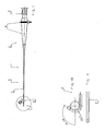
- endoscope 1 consists essentially of a for handling and Actuation of certain proximal portion 2, the eyepiece 3 and a manual operation part. 4 and further comprising a distal one provided for insertion into a body cavity Section 5, which is designed as an insertion tube 6 and which at its distal end 7 a has bendable section 8.
- This bendable section 8 is different from one
- flexible trained insertion tube 6 in that it is controllably bendable, So from the manual control part 4 can be bent in desired directions, as in Figures 1A and 1B shown.
- the pipe segments 9 described in this embodiment are double-walled trained, d. h., They consist of an outer and an inner, each to each other identically formed pipe segment 9 'and 9 ", the only different diameters and possibly also have different wall thicknesses and in a simple manner be pushed into each other.
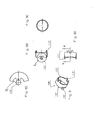
- FIGS. 5A to 5D and FIGS. 8 to 8D the individual elements are shown Pipe segments 9 'at their respective end faces 12 and 13 in the axial direction projecting Connecting means 11, wherein these connecting means 11 two different Have embodiments. So that's on the front side 12 of a pipe segment 9 ' protruding connecting means 11 formed as a pin 14, which in the manner of a circular Disc is cut out of the jacket 15 'of the tube segment 9'.
- the provided on the opposite end face 13 connecting means 11 is against formed as the pin 14 encompassing claws 16, in pairs on the front side 13th are provided. These claws 16 form between them a circular recess, the have the dimensions of the circular disc-shaped pin 14. Also these claws 16 are cut out of the jacket 15 'of the pipe segment 9'.
- the Connecting means 11, they are designed as claws 16 or pin 14, within the Outer or inner circumference of the bendable portion 8 'are, so neither to the inside protrude outwardly and thus the thickness of the shell 15 'of a pipe segment 9' or of the bendable portion 8 'do not exceed. This has the consequence that both the Inner wall and the outer wall of the bendable portion formed smooth surface is.
- the inner bendable portion 8 has at least in its outer peripheral surface two offset by 180 ° in the circumferential direction against each other and arranged over the individual Pipe segments 9 "extending in the axial direction of grooves 23 and 24, in which the here Control cables 10, not shown, run.
- Figs. 7A to 7D show the bendable portion 8 consisting of the outer one bendable portion 8 'and the inner bendable portion 8 "inserted therein.
- the Fig. 7B it can be seen that the total length of the bendable inner Section 8 "is slightly shorter than the total length of the outer bendable section 8 ', This is because the proximal and distal end portions 17 "and 18" shorter, respectively are formed as the corresponding end portions 17 'and 18' of the outer bendable Section 8 '. This difference depends only on purely constructive conditions with The different functions of the end sections are related and none here Role-play.
- a single tube segment 9 'of the outer bendable section is shown 8 ', the special design of the pin or claw-shaped connection means 14 and 16 can be seen.
- Shell 15 'of the tube segment 9' recesses 25 are provided, in which the claws 16 formed connecting means 11 of the opposite tube segment 9 'stand.
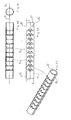
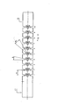
- Fig. 14 shows a bendable section 8 showing nine pipe segments and two end sections, namely the nine respectively identically formed intermediate pipe segments 9 and the respective end pipe segments 17 and 18, respectively, and thus having ten hinge points.
- the drawn in this figure angle ⁇ and ⁇ 1 and the distance a from pin to pin of two adjacent pipe segments 9 can be chosen smaller and / or larger, thereby changing the flexibility of the bendable portion 8.
- the dimensions of these angles and distances can be set by the skilled person as desired.
- the above-described embodiment of the bendable portion 8 is due to the each offset by 180 ° arranged connecting means 11 and due to the presence of only two, each offset by 90 ° to the connecting means around the circumference arranged control cables only in one plane bendable, but it may also be desirable be that the bendable portion in a second, perpendicular to the first plane Level should be bendable, so that ultimately a spatial movement of the bendable Section becomes possible.
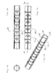
- the tube segments 109 "of the inner bendable Section 108 " show that adjacent to the 180 ° opposite axially extending grooves 123 and 124 for the control cables for moving the bendable Section in a first plane in each case by 90 ° offset two further grooves 123 'and 124' are present for the control cables for bending the bendable section in the second Level are provided.
- FIGS. 11A to 11D show the corresponding pipe segments 109 ". composite inner bendable portion 108 " outer bendable section made of those shown in Figs. 9 to 9C Pipe segments 109 'has been omitted.
- the invention also provides a method for producing the above-described bendable Sections available, the method is characterized in that first rigid pipes 208 'and 208 ", respectively, as shown in FIGS. 3 and 4 are provided each have the desired outer and inner diameter, depending on whether from it inner bendable section 8 "or an outer bendable section 8 'is to be created Inner bendable section 8 "arise, already has to be provided rigid pipe the axially required grooves 23, 24, 23 ', 24', 123, 124, 123 'required for the control cables and 124 'up.
- Such a rigid tube 208 'or 208 "becomes a laser cutting device used, with two alternatives are conceivable, namely that the tube is fixed and the Laser cutting device moves around the pipe and also opposite the pipe in axial direction can be moved, or the laser cutting device in one fixed position is arranged and moved the rigid pipe both in the axial direction as well as can be twisted.
- the laser cutting device is programmed so that either the tube relative to the laser beam or the laser beam relative to the Tube is moved or rotated in the axial and radial directions and the laser beam on a section line SL is performed, which represented in the figures and the pipe segments with the connecting means forming sections produces.
- Fig. 12 is such developed cut line SL for the laser guide and
- Fig. 13 shows the hatched shown and after performing the laser cut on that shown in Fig. 12 Cut line from the rigid tube cut wall parts WT, either be broken out mechanically or by ultrasound.
Abstract
Description
Diese erfindungsgemäßen Verbindungsmittel stehen weder nach außen noch nach innen über die äußere bzw. innere Mantelfläche der Rohrsegmente hervor und es sind auch keine zusätzlichen Mittel vorgesehen, die die Verbindungsmittel aneinanderhalten und dadurch Vorsprünge bilden. Es kann also auf bolzen- und/oder nietenförmige Mittel, die radial ausgerichtete Schwenkachsen bilden und die jeweiligen Verbindungsmittel miteinander schwenkbar verbinden, verzichtet werden. Die Verbindungsmittel sind vielmehr innerhalb der Manteldicke der Rohrsegmente ausgebildet und stehen in axialer Richtung ineinander ein und sind gegeneinander verschwenkbar. Durch diese erfindungsgemäße Ausbildung wird dafür Sorge getragen, daß sowohl die äußere als auch die innere Mantelfläche der Rohrsegmente und damit insbesondere der Innenraum des biegbaren Abschnittes keinerlei Vorsprünge aufweist, es entstehen glattflächige Außen- und Innenseiten.
Diese vorbeschriebene Ausbildung der Verbindungsteile erlaubt es, eine die Rohrsegmente aneinander, haltende und gleichzeitig verschwenkbare Verbindung herzustellen, ohne daß zusätzliche Mittel in Form von Bolzen o. ä. eingesetzt werden müssen. Die klauenförmigen Verbindungsmittel bilden sozusagen eine Klammer zu dem zapfenförmigen Verbindungsmittel des anderen Rohrsegmentes, so daß ein die Rohrsegmente aneinander haltende Verbindung zustande kommt, ohne daß ein zusätzliches, separates Teil als Verbindungsmittel eingesetzt werden muß.
Nach dieser Ausbildung sind die jeweils an einer bestimmten Stirnseite eines Rohrsegmentes vorgesehen Verbindungsmittel, die sich ja um 180° in Umfangsrichtung versetzt gegenüberliegen, identisch ausgebildet, entsprechend dann auch die dazu korrespondierenden zapfen- oder klauenförmigen Verbindungsmittel an der einer solchen Stirnseite eines Rohrsegmentes gegenüberliegenden Stirnseite eines anderen Rohrsegmentes. Diese jeweils identische Ausbildung der Verbindungsmittel an ein und derselben Stirnseite eines Rohrsegmentes vereinfacht die Herstellung solcher Rohrsegmente.
Eine solche Formgebung der Verbindungsmittel gewährleistet, daß diese innerhalb der Abmessungen des Mantels des Rohrsegmentes liegen und gewährleistet insbesondere, daß die Klauen weder in axialer Richtung noch in radialer Richtung von dem Zapfen abgezogen werden können.
Diese jeweiligen ersten und letzten Rohrsegmente des biegbaren Abschnittes sind jeweils ihren entsprechenden Bestimmungen gemäß ausgebildet. So ist das letzte Rohrsegment am distalen Ende des biegbaren Abschnittes zur Aufnahme einer Optik und eines Sensors etc. und insbesondere zum Eindringen in eine Körperhöhle vorgesehen und unterliegt deshalb einer speziellen Ausbildung. Ebenso verhält es sich mit dem am proximalen Ende des biegbaren Abschnittes vorgesehenen Rohrsegment, dieses ist in einer besonderen und hier nicht beschriebenen Form mit dem proximalen Teil des rohrförmigen Einführtubus des Endoskopes verbunden.
Durch die besondere Ausbildung des biegbaren Abschnittes in einer sozusagen doppelwandigen Form, ergibt sich unter Ausbildung der Nuten in der äußeren Umfangsfläche des inneren biegbaren Abschnittes eine sichere Führung für die Steuerzüge, gleichzeitig wird erreicht, daß der Innenraum des doppelwandigen biegbaren Abschnittes, insbesondere also der Innenraum des inneren biegbaren Abschnittes frei bleibt von Seilzügen, wodurch das Einführen von sonstigen Schläuchen, elektrischen Leitungen, etc. sehr vereinfacht wird. Auch ist der Einbau der Seilzüge im doppelwandigen biegbaren Abschnitt verhältnismäßig einfach, müssen die Seilzüge doch nicht durch ösenförmige Führungen hindurchgeführt bzw. in diese eingefädelt werden, vielmehr können die Seilzüge beim Einschieben des inneren biegbaren Abschnittes in den äußeren biegbaren Abschnitt bereits in die jeweiligen Nuten eingelegt und in einem Arbeitsgang eingebaut, andererseits aber auch erst nach dem Zusammenbau des äußeren und inneren biegbaren Abschnittes in die Nuten eingeschoben werden.
Die Anordnung von vier Seilzügen ist erforderlich, wenn der biegbare Abschnitt in zwei Ebenen, also räumlich biegbar sein soll, gleichzeitig müssen dann aber auch die Verbindungsmittel jeweils alternierend, in Umfangsrichtung um 90° versetzt zueinander an den jeweiligen Rohrsegmenten angeordnet sein, damit ein räumliches Abbiegen des biegbaren Abschnittes ermöglicht werden kann.
Eine solche Punktschweißung ist einfach durchzuführen und garantiert die Unverschiebbarkeit der jeweiligen biegbaren Abschnitte zueinander.
Diese Form der Durchführung des Verfahrens erlaubt eine einfachere Konstruktion der Laserschneidevorrichtung.
Dieses Verfahren weist den Vorteil auf, daß keine mechanisch wirkenden Werkzeuge eingesetzt werden müssen.
- Fig. 1:
- eine Seitenansicht auf ein Endoskop, speziell ein Nasopharyngoskop
- Fig. 1A:
- eine etwas vergrößerte Ansicht des distalen Endes eines Einführtubus,
- Fig. 1B:
- eine Ansicht auf das distale Ende gemäß Fig. 1A in einer um ca. 125° abgebogenen Stellung,
- Fig. 2A:
- eine nochmals vergrößerte Ansicht auf das distale Ende gemäß Fig. 1A, versehen mit einer teilweise aufgebrochenen schlauchförmigen Kunststoffumhüllung,
- Fig. 2B:
- eine Ansicht auf das distale Ende gemäß Fig. 2A, jedoch in einer abgebogenen Stellung,
- Fig. 3:
- eine Ansicht auf ein biegesteifes Rohr vor der Ausbildung zu einem äußeren biegbaren Abschnitt des Einführtubus,
- Fig. 4:
- eine Ansicht auf ein biegesteifes Rohr vor der Ausbildung zu einem inneren biegbaren Abschnitt des Einführtubus,
- Fig. 5A:
- eine Draufsicht auf den äußeren biegbaren Abschnitt,
- Fig. 5B:
- einen Längsschnitt gemäß Linie B-B in Fig. 5A,
- Fig. 5C:
- eine Stirnansicht auf den äußeren biegbaren Abschnitt,
- Fig. 5D:
- eine perspektivische Seitenansicht des äußeren biegbaren Abschnitts gemäß Fig. 5A,
- Fig. 6A:
- eine Draufsicht auf den inneren biegbaren Abschnitt des Einführtubus,
- Fig. 6B:
- einen Schnitt durch den inneren biegbaren Abschnitt gemäß Linie B-B in Fig. 6A,
- Fig. 6C:
- eine Stirnansicht auf den inneren biegbaren Abschnitt,
- Fig. 6D:
- eine perspektivische Seitenansicht des inneren biegbaren Abschnitts gemäß Fig. 6A,
- Fig. 7A:
- eine Draufsicht auf das biegbare distale Ende des Einführtubus, bestehend aus äußerem und innerem biegbaren Abschnitt,
- Fig. 7B:
- einen Schnitt gemäß Linie B-B durch das biegbare distale Ende gemäß Fig. 7A,
- Fig. 7C:
- eine Stirnansicht auf das biegbare distale Ende mit äußerem und innerem biegbaren Abschnitt,
- Fig. 7D:
- eine perspektivische Seitenansicht auf das biegbare distale Ende gemäß Fig. 7A,
- Fig. 8:
- eine perspektivische Darstellung auf ein einzelnes Rohrsegment des äußeren biegbaren Abschnitts,
- Fig. 8A:
- eine Draufsicht auf das Rohrsegment gemäß Fig. 8,
- Fig. 8B:
- einen Schnitt gemäß Linie B-B in Fig. 8A durch das Rohrsegment,
- Fig. 8C:
- eine Stirnansicht auf das Rohrsegment,
- Fig. 8D:
- eine vergrößerte Darstellung des Details D gemäß Fig. 8B,
- Fig. 9:
- eine perspektivische Seitenansicht auf ein Rohrsegment des äußeren Abschnitts, bei dem die Verbindungsmittel an einer ersten Stirnseite um 90° zu den Verbindungsmitteln an der anderen Stirnseite versetzt angeordnet sind,
- Fig. 9A:
- eine Draufsicht auf das Rohrsegment gemäß Fig. 9,
- Fig. 9B:
- einen Schnitt gemäß Linie B-B in Fig. 9A durch das Rohrsegment,
- Fig. 9C:
- eine Stirnansicht des Rohrsegmentes,
- Fig. 9D:
- eine vergrößerte Darstellung des Details D in Fig. 9B
- Fig. 10:
- eine perspektivische Seitenansicht auf ein Rohrsegment des inneren biegbaren Abschnitts mit entsprechender Anordnung der zueinander versetzten Verbindungsmittel gemäß Fig. 9,
- Fig. 10A:
- eine Draufsicht auf das Rohrsegment gemäß Fig. 10,
- Fig. 10B:
- einen Schnitt durch das Rohrsegment gemäß Linie B-B in Fig. 10A,
- Fig. 10C:
- eine Stirnansicht auf das Rohrsegment,
- Fig. 10D:
- eine Ansicht der gegenüberliegenden Stirnseite des Rohrsegmentes,
- Fig. 11A:
- eine Draufsicht auf einen inneren biegbaren Abschnitt für 4-fach Seilzüge,
- Fig. 11B:
- einen Schnitt durch den inneren biegbaren Abschnitt gemäß Linie B-B in Fig. 11A,
- Fig. 11C:
- eine Stirnansicht auf den inneren biegbaren Abschnitt,
- Fig. 11D:
- eine perspektivische Seitenansicht auf den inneren biegbaren Abschnitt für 4-fach Seilzüge,
- Fig. 12:
- Darstellung der Laserschnittlinie in abgewickelter Form,
- Fig. 13:
- Darstellung der aus dem Rohr herauszubrechenden freigeschnittenen Wandteile und
- Fig. 14:
- Darstellung eines biegbaren Abschnitts mit Abstands -und Winkelangaben.
Claims (11)
- Biegbarer Abschnitt (8, 8', 8"), der am distalen Ende (7) eines Einführtubus (6) eines Endoskopes (1) angeordnet ist, umfassend eine Mehrzahl von Rohrsegmenten (9, 9', 9", 109', 109"), wobei jedes dieser Rohrsegmente (9, 9', 9", 109', 109") Verbindungsmittel (11, 111', 111'') aufweist, die mit den Verbindungsmitteln (11, 111', 111") des benachbarten Rohrsegmentes (9, 9', 9", 109', 109") zusammenwirken, sowie Steuerzüge (10), mit denen die Abbiegung des biegbaren Abschnittes (8, 8', 8") steuerbar ist, dadurch gekennzeichnet, daß die jeweiligen Verbindungsmittel (11, 111', 111") eines Rohrsegmentes (9, 9', 9", 109', 109") an dessen Stirnseiten (12, 112', 112" bzw. 13, 113', 113") in axialer Richtung vorstehend und innerhalb des Mantels (15, bzw. 15") des Rohrsegmentes (9, 9', 9", 109', 109") liegend ausgebildet sind und die Dicke des Mantels (15, 15") nicht überschreiten, wobei die Verbindungsmittel (11, 111', 111"), die an den jeweiligen Stirnseiten (12, 112', 112" bzw. 13, 113', 113") benachbarter Rohrsegmente (9, 9', 9", 109', 109") vorgesehen sind und sich gegenüberliegen, sich nach Art einer scharnierförmigen Verbindung ergänzen.
- Biegbarer Abschnitt nach Anspruch 1, dadurch gekennzeichnet, daß die an der einen Stirnseite (12, 112', 112") eines Rohrsegmentes (9, 9', 9", 109', 109") ausgebildeten Stirnseite (12, 112', 112") eines Rohrsegmentes (9, 9', 9", 109', 109") ausgebildeten Verbindungsmittel (11, 111', 111") nach Art eines zur Stirnseite (13, 113', 113") eines benachbarten Rohrsegmentes (9, 9', 9", 109', 109") gerichtete und vorstehende Zapfen (14, 114', 114") ausgebildet sind, und daß die an der anderen Stirnseite (13, 113', 113") des Rohrsegmentes (9, 9', 9") angeordneten Verbindungsmittel (11, 111', 111") als den Zapfen (14, 114', 114") eines benachbarten Rohrsegmentes (9, 9', 9") umgreifende Klauen (16, 116', 116") ausgebildet sind, wobei sowohl der Zapfen (14, 114', 114") als auch die Klauen (16, 116', 116") Teile des Mantels (15', 15") des jeweiligen Rohrsegmentes (9, 9', 9", 109', 109") sind.
- Biegbarer Abschnitt nach Anspruch 2, dadurch gekennzeichnet, daß die jeweils an einer der Stirnseiten (12, 112', 112" bzw. 13, 113', 113") eines Rohrsegmentes (9, 9', 9", 109', 109") angeordneten Verbindungsmittel (11, 111', 111") entweder als Zapfen (14, 114', 114") oder als Klauen (16, 116', 116") ausgebildet sind, wobei dann die an der anderen Stirnseite (13, 113', 113" bzw. 14, 114', 114") des selben Rohrsegmentes (9, 9', 9", 109', 109") vorgesehenen Verbindungsmittel (11, 111', 111") entweder als Klauen (16, 116', 116") oder als Zapfen (14, 114', 114") ausgebildet sind.
- Biegbarer Abschnitt nach Anspruch 2, dadurch gekennzeichnet, daß der an der Stirnseite (12, 112', 112") eines Rohrsegmentes (9, 9', 9", 109', 109") angeordnete Zapfen (14, 114', 114") nach Art einer kreisförmigen Scheibe ausgebildet ist und daß die an der Stirnseite (13, 113', 113") des benachbarten Rohrsegmentes (9, 9', 9", 109', 109") vorgesehenen Klauen (16, 116', 116") eine kreisförmige Ausnehmung zwischen sich einschließen, welche die Abmessungen des kreisscheibenförmigen Zapfens (14, 114', 114") aufweist, und wobei die Klauen (16, 116', 116") den Zapfen (14, 114', 114") in dieser Ausnehmung aufnehmen.
- Biegbarer Abschnitt nach einem der vorstehenden Ansprüche, dadurch gekennzeichnet, daß das am proximalen Ende des biegbaren Abschnittes (8, 8', 8") angeordnete erste Rohrsegment (17', 17") und das am distalen Ende des biegbaren Abschnittes (8, 8', 8") angeordnete letzte Rohrsegment (18', 18") jeweils an ihren die Enden (19', 19" bzw. 20', 20") des biegbaren Rohrsabschnitts bildenden Stirnseiten (21', 21" bzw. 22',22") keine Verbindungsmittel nach Art von Zapfen und/oder Klauen aufweisen.
- Biegbarer Abschnitt nach einem der vorstehenden Ansprüche, dadurch gekennzeichnet, daß in dem biegbaren Abschnitt (8') ein hinsichtlich der Anzahl der Rohrsegmente (9') und der Anordnung der Verbindungsmittel (11) an diesen Rohrsegmenten (9') identisch ausgebildeter zweiter, innerer biegbarer Abschnitt (8") eingesetzt ist, dessen Außendurchmesser dem Innendurchmesser des äußeren biegbaren Abschnittes (8') so angepaßt ist, daß der innere biegbare Abschnitt (8") in den äußeren biegbaren Abschnitt (8') einschiebbar ist, und wobei der innere biegbare Abschnitt (8") in seiner äußeren Umfangsfläche mindestens zwei um 180° in Umfangsrichtung gegeneinander versetzt angeordnete und über die einzelnen Rohrsegmente (9", 109") in axialer Richtung verlaufende Nuten (23 bzw. 24) aufweist, in welchen jeweils ein Steuerzug (10) geführt ist, wobei die beiden Nuten (23 bzw. 24) jeweils in Umfangsrichtung um 90° versetzt gegenüber den Verbindungsmitteln (11) angeordnet sind.
- Biegbarer Abschnitt nach Anspruch 6, dadurch gekennzeichnet, daß an der äußeren Umfangsfläche des inneren biegbaren Abschnitts (8") vier axial verlaufende Nuten (123, 123'; 124, 124') vorgesehen sind, die jeweils um 90° in Umfangsrichtung zueinander versetzt angeordnet sind, wobei gleichzeitig die an den jeweiligen Stirnseiten (112', 112" bzw. 113', 113") eines Rohrsegmentes (109', 109") paarweise angeordneten Verbindungsteile (111', 111 ") um 90° zueinander versetzt sind.
- Biegbarer Abschnitt nach einem der Ansprüche 6 oder 7, dadurch gekennzeichnet, daß die einzelnen Rohrsegmente (9, 9', 9", 109', 109") der inneren und der äußeren biegbaren Abschnitte (8, 8' bzw. 8") im Zustand ihrer vollständigen Kongruenz zueinander, jeweils miteinander durch eine Punktschweißung aneinander fixiert sind.
- Verfahren zur Herstellung eines biegbaren Abschnittes, der eine Vielzahl von Rohrsegmenten aufweist, welche in einer Reihe hintereinander angeordnet und miteinander über Verbindungsteile gegeneinander schwenkbar miteinander verbunden sind, wobei das Verfahren folgende Schritte umfaßt:f) Bereitstellen eines biegesteifen Rohres, das Abmessungen aufweist, die den gewünschten Abmessungen des biegbaren Abschnittes entsprechen,g) Bereitstellen einer Laser-Schneidevorrichtung,h) Einsetzen des biegesteifen Rohres in die Laser-Schneidevorrichtung,i) Führung des Laserstrahles der Laser-Schneidevorrichtung entsprechend den aufgrund der Konfiguration der Rohrsegmente und der jeweiligen Verbindungsmittel vorgegebenen Schnittlinien, wobei der Laserstrahl stets radial auf das Rohr gerichtet ist, undj) Herausbrechen der aus dem biegesteifen Rohr herausgeschnittenen Wandteile zur Ermöglichung der Verschwenkbarkeit der einzelnen Rohrsegmente zueinander.
- Verfahren nach Anspruch 9, dadurch gekennzeichnet, daß das biegesteife Rohr in der Schneidevorrichtung unter dem ortsfesten Laserstrahl gedreht und/oder axial verschoben wird.
- Verfahren nach Anspruch 9, dadurch gekennzeichnet, daß die aus dem Rohr herausgeschnittenen Wandteile mittels Ultraschalls herausgebrochen werden.
Applications Claiming Priority (2)
| Application Number | Priority Date | Filing Date | Title |
|---|---|---|---|
| DE102004027850A DE102004027850A1 (de) | 2004-06-08 | 2004-06-08 | Biegbarer Abschnitt eines Einführtubus eines Endoskopes und Verfahren zu dessen Herstellung |
| DE102004027850 | 2004-06-08 |
Publications (2)
| Publication Number | Publication Date |
|---|---|
| EP1604607A1 true EP1604607A1 (de) | 2005-12-14 |
| EP1604607B1 EP1604607B1 (de) | 2006-10-04 |
Family
ID=34937051
Family Applications (1)
| Application Number | Title | Priority Date | Filing Date |
|---|---|---|---|
| EP05011624A Not-in-force EP1604607B1 (de) | 2004-06-08 | 2005-05-30 | Biegbarer Abschnitt eines Einführtubus eines Endoskopes und Verfahren zu dessen Herstellung |
Country Status (6)
| Country | Link |
|---|---|
| US (1) | US7766821B2 (de) |
| EP (1) | EP1604607B1 (de) |
| CN (1) | CN100508869C (de) |
| AT (1) | ATE341271T1 (de) |
| DE (2) | DE102004027850A1 (de) |
| ES (1) | ES2273299T3 (de) |
Cited By (5)
| Publication number | Priority date | Publication date | Assignee | Title |
|---|---|---|---|---|
| EP1870017A1 (de) * | 2006-06-23 | 2007-12-26 | Olympus Medical Systems Corp. | Endoskopeinführteil |
| WO2014107393A1 (en) | 2013-01-03 | 2014-07-10 | Just Right Surgical, Llc | Medical device and method of use |
| US9750497B2 (en) | 2013-01-03 | 2017-09-05 | Just Right Surgical, Llc | Device for use in laparoscopic surgery and method of use |
| WO2021144542A1 (fr) | 2020-01-17 | 2021-07-22 | Axess Vision Technology | Structure de flexion découpée pour dispositif médical |
| US11653921B2 (en) | 2020-05-04 | 2023-05-23 | Bolder Surgical, Llc | Anti-buckling actuation members for a surgical instrument |
Families Citing this family (542)
| Publication number | Priority date | Publication date | Assignee | Title |
|---|---|---|---|---|
| AU744956B2 (en) | 1998-03-20 | 2002-03-07 | Boston Scientific Limited | Endoscopic suture systems |
| US20040199052A1 (en) * | 2003-04-01 | 2004-10-07 | Scimed Life Systems, Inc. | Endoscopic imaging system |
| US7591783B2 (en) | 2003-04-01 | 2009-09-22 | Boston Scientific Scimed, Inc. | Articulation joint for video endoscope |
| US20050245789A1 (en) | 2003-04-01 | 2005-11-03 | Boston Scientific Scimed, Inc. | Fluid manifold for endoscope system |
| US8118732B2 (en) | 2003-04-01 | 2012-02-21 | Boston Scientific Scimed, Inc. | Force feedback control system for video endoscope |
| US7578786B2 (en) | 2003-04-01 | 2009-08-25 | Boston Scientific Scimed, Inc. | Video endoscope |
| US20070084897A1 (en) | 2003-05-20 | 2007-04-19 | Shelton Frederick E Iv | Articulating surgical stapling instrument incorporating a two-piece e-beam firing mechanism |
| US9060770B2 (en) | 2003-05-20 | 2015-06-23 | Ethicon Endo-Surgery, Inc. | Robotically-driven surgical instrument with E-beam driver |
| US20050165275A1 (en) * | 2004-01-22 | 2005-07-28 | Kenneth Von Felten | Inspection device insertion tube |
| US8215531B2 (en) | 2004-07-28 | 2012-07-10 | Ethicon Endo-Surgery, Inc. | Surgical stapling instrument having a medical substance dispenser |
| US11896225B2 (en) | 2004-07-28 | 2024-02-13 | Cilag Gmbh International | Staple cartridge comprising a pan |
| US8083671B2 (en) | 2004-09-30 | 2011-12-27 | Boston Scientific Scimed, Inc. | Fluid delivery system for use with an endoscope |
| EP1799095A2 (de) | 2004-09-30 | 2007-06-27 | Boston Scientific Scimed, Inc. | Adapter zur verwendung mit einem digitalen bildgebenden medizinprodukt |
| US7479106B2 (en) * | 2004-09-30 | 2009-01-20 | Boston Scientific Scimed, Inc. | Automated control of irrigation and aspiration in a single-use endoscope |
| US8052597B2 (en) | 2005-08-30 | 2011-11-08 | Boston Scientific Scimed, Inc. | Method for forming an endoscope articulation joint |
| US8317070B2 (en) | 2005-08-31 | 2012-11-27 | Ethicon Endo-Surgery, Inc. | Surgical stapling devices that produce formed staples having different lengths |
| US9237891B2 (en) | 2005-08-31 | 2016-01-19 | Ethicon Endo-Surgery, Inc. | Robotically-controlled surgical stapling devices that produce formed staples having different lengths |
| US10159482B2 (en) | 2005-08-31 | 2018-12-25 | Ethicon Llc | Fastener cartridge assembly comprising a fixed anvil and different staple heights |
| US7669746B2 (en) | 2005-08-31 | 2010-03-02 | Ethicon Endo-Surgery, Inc. | Staple cartridges for forming staples having differing formed staple heights |
| US8800838B2 (en) | 2005-08-31 | 2014-08-12 | Ethicon Endo-Surgery, Inc. | Robotically-controlled cable-based surgical end effectors |
| US11484312B2 (en) | 2005-08-31 | 2022-11-01 | Cilag Gmbh International | Staple cartridge comprising a staple driver arrangement |
| US11246590B2 (en) | 2005-08-31 | 2022-02-15 | Cilag Gmbh International | Staple cartridge including staple drivers having different unfired heights |
| US7934630B2 (en) | 2005-08-31 | 2011-05-03 | Ethicon Endo-Surgery, Inc. | Staple cartridges for forming staples having differing formed staple heights |
| US20070106317A1 (en) | 2005-11-09 | 2007-05-10 | Shelton Frederick E Iv | Hydraulically and electrically actuated articulation joints for surgical instruments |
| US20110024477A1 (en) | 2009-02-06 | 2011-02-03 | Hall Steven G | Driven Surgical Stapler Improvements |
| US11278279B2 (en) | 2006-01-31 | 2022-03-22 | Cilag Gmbh International | Surgical instrument assembly |
| US11793518B2 (en) | 2006-01-31 | 2023-10-24 | Cilag Gmbh International | Powered surgical instruments with firing system lockout arrangements |
| US8708213B2 (en) | 2006-01-31 | 2014-04-29 | Ethicon Endo-Surgery, Inc. | Surgical instrument having a feedback system |
| US8763879B2 (en) | 2006-01-31 | 2014-07-01 | Ethicon Endo-Surgery, Inc. | Accessing data stored in a memory of surgical instrument |
| US9861359B2 (en) | 2006-01-31 | 2018-01-09 | Ethicon Llc | Powered surgical instruments with firing system lockout arrangements |
| US8161977B2 (en) | 2006-01-31 | 2012-04-24 | Ethicon Endo-Surgery, Inc. | Accessing data stored in a memory of a surgical instrument |
| US7753904B2 (en) | 2006-01-31 | 2010-07-13 | Ethicon Endo-Surgery, Inc. | Endoscopic surgical instrument with a handle that can articulate with respect to the shaft |
| US8186555B2 (en) | 2006-01-31 | 2012-05-29 | Ethicon Endo-Surgery, Inc. | Motor-driven surgical cutting and fastening instrument with mechanical closure system |
| US20110295295A1 (en) | 2006-01-31 | 2011-12-01 | Ethicon Endo-Surgery, Inc. | Robotically-controlled surgical instrument having recording capabilities |
| US8820603B2 (en) | 2006-01-31 | 2014-09-02 | Ethicon Endo-Surgery, Inc. | Accessing data stored in a memory of a surgical instrument |
| US20110006101A1 (en) | 2009-02-06 | 2011-01-13 | EthiconEndo-Surgery, Inc. | Motor driven surgical fastener device with cutting member lockout arrangements |
| US11224427B2 (en) | 2006-01-31 | 2022-01-18 | Cilag Gmbh International | Surgical stapling system including a console and retraction assembly |
| US20120292367A1 (en) | 2006-01-31 | 2012-11-22 | Ethicon Endo-Surgery, Inc. | Robotically-controlled end effector |
| US7845537B2 (en) | 2006-01-31 | 2010-12-07 | Ethicon Endo-Surgery, Inc. | Surgical instrument having recording capabilities |
| US20070185519A1 (en) * | 2006-02-07 | 2007-08-09 | Hassler William L Jr | Articulating surgical instrument |
| US20070225562A1 (en) | 2006-03-23 | 2007-09-27 | Ethicon Endo-Surgery, Inc. | Articulating endoscopic accessory channel |
| US8992422B2 (en) | 2006-03-23 | 2015-03-31 | Ethicon Endo-Surgery, Inc. | Robotically-controlled endoscopic accessory channel |
| US7955255B2 (en) | 2006-04-20 | 2011-06-07 | Boston Scientific Scimed, Inc. | Imaging assembly with transparent distal cap |
| US8202265B2 (en) | 2006-04-20 | 2012-06-19 | Boston Scientific Scimed, Inc. | Multiple lumen assembly for use in endoscopes or other medical devices |
| US8322455B2 (en) | 2006-06-27 | 2012-12-04 | Ethicon Endo-Surgery, Inc. | Manually driven surgical cutting and fastening instrument |
| US10130359B2 (en) | 2006-09-29 | 2018-11-20 | Ethicon Llc | Method for forming a staple |
| US10568652B2 (en) | 2006-09-29 | 2020-02-25 | Ethicon Llc | Surgical staples having attached drivers of different heights and stapling instruments for deploying the same |
| US8220690B2 (en) | 2006-09-29 | 2012-07-17 | Ethicon Endo-Surgery, Inc. | Connected surgical staples and stapling instruments for deploying the same |
| US8684253B2 (en) | 2007-01-10 | 2014-04-01 | Ethicon Endo-Surgery, Inc. | Surgical instrument with wireless communication between a control unit of a robotic system and remote sensor |
| US8459520B2 (en) | 2007-01-10 | 2013-06-11 | Ethicon Endo-Surgery, Inc. | Surgical instrument with wireless communication between control unit and remote sensor |
| US8652120B2 (en) | 2007-01-10 | 2014-02-18 | Ethicon Endo-Surgery, Inc. | Surgical instrument with wireless communication between control unit and sensor transponders |
| US11291441B2 (en) | 2007-01-10 | 2022-04-05 | Cilag Gmbh International | Surgical instrument with wireless communication between control unit and remote sensor |
| US8827133B2 (en) | 2007-01-11 | 2014-09-09 | Ethicon Endo-Surgery, Inc. | Surgical stapling device having supports for a flexible drive mechanism |
| US11039836B2 (en) | 2007-01-11 | 2021-06-22 | Cilag Gmbh International | Staple cartridge for use with a surgical stapling instrument |
| US7669747B2 (en) | 2007-03-15 | 2010-03-02 | Ethicon Endo-Surgery, Inc. | Washer for use with a surgical stapling instrument |
| US8893946B2 (en) | 2007-03-28 | 2014-11-25 | Ethicon Endo-Surgery, Inc. | Laparoscopic tissue thickness and clamp load measuring devices |
| WO2008144077A1 (en) | 2007-05-18 | 2008-11-27 | Boston Scientific Scimed, Inc. | Drive systems and methods of use |
| US7832408B2 (en) | 2007-06-04 | 2010-11-16 | Ethicon Endo-Surgery, Inc. | Surgical instrument having a directional switching mechanism |
| US11857181B2 (en) | 2007-06-04 | 2024-01-02 | Cilag Gmbh International | Robotically-controlled shaft based rotary drive systems for surgical instruments |
| US8534528B2 (en) | 2007-06-04 | 2013-09-17 | Ethicon Endo-Surgery, Inc. | Surgical instrument having a multiple rate directional switching mechanism |
| US8931682B2 (en) | 2007-06-04 | 2015-01-13 | Ethicon Endo-Surgery, Inc. | Robotically-controlled shaft based rotary drive systems for surgical instruments |
| US7753245B2 (en) | 2007-06-22 | 2010-07-13 | Ethicon Endo-Surgery, Inc. | Surgical stapling instruments |
| US8408439B2 (en) | 2007-06-22 | 2013-04-02 | Ethicon Endo-Surgery, Inc. | Surgical stapling instrument with an articulatable end effector |
| US11849941B2 (en) | 2007-06-29 | 2023-12-26 | Cilag Gmbh International | Staple cartridge having staple cavities extending at a transverse angle relative to a longitudinal cartridge axis |
| US8561870B2 (en) | 2008-02-13 | 2013-10-22 | Ethicon Endo-Surgery, Inc. | Surgical stapling instrument |
| US8573465B2 (en) | 2008-02-14 | 2013-11-05 | Ethicon Endo-Surgery, Inc. | Robotically-controlled surgical end effector system with rotary actuated closure systems |
| US9179912B2 (en) | 2008-02-14 | 2015-11-10 | Ethicon Endo-Surgery, Inc. | Robotically-controlled motorized surgical cutting and fastening instrument |
| US8752749B2 (en) | 2008-02-14 | 2014-06-17 | Ethicon Endo-Surgery, Inc. | Robotically-controlled disposable motor-driven loading unit |
| US7866527B2 (en) | 2008-02-14 | 2011-01-11 | Ethicon Endo-Surgery, Inc. | Surgical stapling apparatus with interlockable firing system |
| US8459525B2 (en) | 2008-02-14 | 2013-06-11 | Ethicon Endo-Sugery, Inc. | Motorized surgical cutting and fastening instrument having a magnetic drive train torque limiting device |
| US7819298B2 (en) | 2008-02-14 | 2010-10-26 | Ethicon Endo-Surgery, Inc. | Surgical stapling apparatus with control features operable with one hand |
| US7793812B2 (en) | 2008-02-14 | 2010-09-14 | Ethicon Endo-Surgery, Inc. | Disposable motor-driven loading unit for use with a surgical cutting and stapling apparatus |
| US8622274B2 (en) | 2008-02-14 | 2014-01-07 | Ethicon Endo-Surgery, Inc. | Motorized cutting and fastening instrument having control circuit for optimizing battery usage |
| BRPI0901282A2 (pt) | 2008-02-14 | 2009-11-17 | Ethicon Endo Surgery Inc | instrumento cirúrgico de corte e fixação dotado de eletrodos de rf |
| US8636736B2 (en) | 2008-02-14 | 2014-01-28 | Ethicon Endo-Surgery, Inc. | Motorized surgical cutting and fastening instrument |
| US8758391B2 (en) | 2008-02-14 | 2014-06-24 | Ethicon Endo-Surgery, Inc. | Interchangeable tools for surgical instruments |
| US8584919B2 (en) | 2008-02-14 | 2013-11-19 | Ethicon Endo-Sugery, Inc. | Surgical stapling apparatus with load-sensitive firing mechanism |
| US8657174B2 (en) | 2008-02-14 | 2014-02-25 | Ethicon Endo-Surgery, Inc. | Motorized surgical cutting and fastening instrument having handle based power source |
| US11272927B2 (en) | 2008-02-15 | 2022-03-15 | Cilag Gmbh International | Layer arrangements for surgical staple cartridges |
| US9770245B2 (en) | 2008-02-15 | 2017-09-26 | Ethicon Llc | Layer arrangements for surgical staple cartridges |
| US7832612B2 (en) | 2008-09-19 | 2010-11-16 | Ethicon Endo-Surgery, Inc. | Lockout arrangement for a surgical stapler |
| PL3476312T3 (pl) | 2008-09-19 | 2024-03-11 | Ethicon Llc | Stapler chirurgiczny z urządzeniem do dopasowania wysokości zszywek |
| US11648005B2 (en) | 2008-09-23 | 2023-05-16 | Cilag Gmbh International | Robotically-controlled motorized surgical instrument with an end effector |
| US9050083B2 (en) | 2008-09-23 | 2015-06-09 | Ethicon Endo-Surgery, Inc. | Motorized surgical instrument |
| US8210411B2 (en) | 2008-09-23 | 2012-07-03 | Ethicon Endo-Surgery, Inc. | Motor-driven surgical cutting instrument |
| US9005230B2 (en) | 2008-09-23 | 2015-04-14 | Ethicon Endo-Surgery, Inc. | Motorized surgical instrument |
| US9386983B2 (en) | 2008-09-23 | 2016-07-12 | Ethicon Endo-Surgery, Llc | Robotically-controlled motorized surgical instrument |
| US8608045B2 (en) | 2008-10-10 | 2013-12-17 | Ethicon Endo-Sugery, Inc. | Powered surgical cutting and stapling apparatus with manually retractable firing system |
| US8397971B2 (en) | 2009-02-05 | 2013-03-19 | Ethicon Endo-Surgery, Inc. | Sterilizable surgical instrument |
| US8517239B2 (en) | 2009-02-05 | 2013-08-27 | Ethicon Endo-Surgery, Inc. | Surgical stapling instrument comprising a magnetic element driver |
| US8414577B2 (en) | 2009-02-05 | 2013-04-09 | Ethicon Endo-Surgery, Inc. | Surgical instruments and components for use in sterile environments |
| CA2751664A1 (en) | 2009-02-06 | 2010-08-12 | Ethicon Endo-Surgery, Inc. | Driven surgical stapler improvements |
| US8444036B2 (en) | 2009-02-06 | 2013-05-21 | Ethicon Endo-Surgery, Inc. | Motor driven surgical fastener device with mechanisms for adjusting a tissue gap within the end effector |
| US7918376B1 (en) | 2009-03-09 | 2011-04-05 | Cardica, Inc. | Articulated surgical instrument |
| DE102009017175B4 (de) * | 2009-04-09 | 2011-05-05 | Richard Wolf Gmbh | Verfahren zur Herstellung eines abwinkelbaren Rohrs |
| US8096457B1 (en) | 2009-05-05 | 2012-01-17 | Cardica, Inc. | Articulation mechanisms for surgical instrument |
| US9289208B1 (en) | 2009-05-05 | 2016-03-22 | Cardica, Inc. | Articulation insert for surgical instrument |
| US20110034771A1 (en) * | 2009-08-07 | 2011-02-10 | Gyrus Acmi, Inc. | Endoscope resilient deflection section frame |
| JP5653604B2 (ja) * | 2009-09-17 | 2015-01-14 | オリンパス株式会社 | 内視鏡湾曲部 |
| US8220688B2 (en) | 2009-12-24 | 2012-07-17 | Ethicon Endo-Surgery, Inc. | Motor-driven surgical cutting instrument with electric actuator directional control assembly |
| US8851354B2 (en) | 2009-12-24 | 2014-10-07 | Ethicon Endo-Surgery, Inc. | Surgical cutting instrument that analyzes tissue thickness |
| DE102010002334A1 (de) | 2010-02-25 | 2011-08-25 | Henke-Sass, Wolf GmbH, 78532 | Endoskop |
| WO2011127137A1 (en) | 2010-04-06 | 2011-10-13 | Pavel Menn | Articulating steerable clip applier for laparoscopic procedures |
| US8783543B2 (en) | 2010-07-30 | 2014-07-22 | Ethicon Endo-Surgery, Inc. | Tissue acquisition arrangements and methods for surgical stapling devices |
| US8360296B2 (en) | 2010-09-09 | 2013-01-29 | Ethicon Endo-Surgery, Inc. | Surgical stapling head assembly with firing lockout for a surgical stapler |
| US9877720B2 (en) | 2010-09-24 | 2018-01-30 | Ethicon Llc | Control features for articulating surgical device |
| US8733613B2 (en) | 2010-09-29 | 2014-05-27 | Ethicon Endo-Surgery, Inc. | Staple cartridge |
| BR112013007717B1 (pt) | 2010-09-30 | 2020-09-24 | Ethicon Endo-Surgery, Inc. | Sistema de grampeamento cirúrgico |
| US9220500B2 (en) | 2010-09-30 | 2015-12-29 | Ethicon Endo-Surgery, Inc. | Tissue thickness compensator comprising structure to produce a resilient load |
| US9220501B2 (en) | 2010-09-30 | 2015-12-29 | Ethicon Endo-Surgery, Inc. | Tissue thickness compensators |
| US8893949B2 (en) | 2010-09-30 | 2014-11-25 | Ethicon Endo-Surgery, Inc. | Surgical stapler with floating anvil |
| US9414838B2 (en) | 2012-03-28 | 2016-08-16 | Ethicon Endo-Surgery, Llc | Tissue thickness compensator comprised of a plurality of materials |
| US9301753B2 (en) | 2010-09-30 | 2016-04-05 | Ethicon Endo-Surgery, Llc | Expandable tissue thickness compensator |
| US11298125B2 (en) | 2010-09-30 | 2022-04-12 | Cilag Gmbh International | Tissue stapler having a thickness compensator |
| US9332974B2 (en) | 2010-09-30 | 2016-05-10 | Ethicon Endo-Surgery, Llc | Layered tissue thickness compensator |
| US20120080478A1 (en) | 2010-09-30 | 2012-04-05 | Ethicon Endo-Surgery, Inc. | Surgical staple cartridges with detachable support structures and surgical stapling instruments with systems for preventing actuation motions when a cartridge is not present |
| US9320523B2 (en) | 2012-03-28 | 2016-04-26 | Ethicon Endo-Surgery, Llc | Tissue thickness compensator comprising tissue ingrowth features |
| US9592050B2 (en) | 2010-09-30 | 2017-03-14 | Ethicon Endo-Surgery, Llc | End effector comprising a distal tissue abutment member |
| US9351730B2 (en) | 2011-04-29 | 2016-05-31 | Ethicon Endo-Surgery, Llc | Tissue thickness compensator comprising channels |
| US9629814B2 (en) | 2010-09-30 | 2017-04-25 | Ethicon Endo-Surgery, Llc | Tissue thickness compensator configured to redistribute compressive forces |
| US9216019B2 (en) | 2011-09-23 | 2015-12-22 | Ethicon Endo-Surgery, Inc. | Surgical stapler with stationary staple drivers |
| US11849952B2 (en) | 2010-09-30 | 2023-12-26 | Cilag Gmbh International | Staple cartridge comprising staples positioned within a compressible portion thereof |
| US9314246B2 (en) | 2010-09-30 | 2016-04-19 | Ethicon Endo-Surgery, Llc | Tissue stapler having a thickness compensator incorporating an anti-inflammatory agent |
| US10945731B2 (en) | 2010-09-30 | 2021-03-16 | Ethicon Llc | Tissue thickness compensator comprising controlled release and expansion |
| US9307989B2 (en) | 2012-03-28 | 2016-04-12 | Ethicon Endo-Surgery, Llc | Tissue stapler having a thickness compensator incorportating a hydrophobic agent |
| US9364233B2 (en) | 2010-09-30 | 2016-06-14 | Ethicon Endo-Surgery, Llc | Tissue thickness compensators for circular surgical staplers |
| US9517063B2 (en) | 2012-03-28 | 2016-12-13 | Ethicon Endo-Surgery, Llc | Movable member for use with a tissue thickness compensator |
| US8978954B2 (en) | 2010-09-30 | 2015-03-17 | Ethicon Endo-Surgery, Inc. | Staple cartridge comprising an adjustable distal portion |
| US11812965B2 (en) | 2010-09-30 | 2023-11-14 | Cilag Gmbh International | Layer of material for a surgical end effector |
| US8695866B2 (en) | 2010-10-01 | 2014-04-15 | Ethicon Endo-Surgery, Inc. | Surgical instrument having a power control circuit |
| US9055960B2 (en) | 2010-11-15 | 2015-06-16 | Intuitive Surgical Operations, Inc. | Flexible surgical devices |
| WO2012121877A1 (en) * | 2011-03-10 | 2012-09-13 | Boston Scientific Scimed, Inc. | Flexible suturing instrument |
| US9113884B2 (en) | 2011-03-14 | 2015-08-25 | Ethicon Endo-Surgery, Inc. | Modular surgical tool systems |
| CN102706895B (zh) * | 2011-03-28 | 2014-07-23 | 海洋王照明科技股份有限公司 | 单管导向管壁检测工具 |
| CN102706896B (zh) * | 2011-03-28 | 2014-05-07 | 海洋王照明科技股份有限公司 | 多管路的侧壁导向管壁检测工具 |
| US9038880B1 (en) | 2011-04-25 | 2015-05-26 | Cardica, Inc. | Articulated surgical instrument |
| US9566048B1 (en) | 2011-04-26 | 2017-02-14 | Cardica, Inc. | Surgical instrument with discrete cammed articulation |
| US9474527B1 (en) | 2011-04-26 | 2016-10-25 | Bryan D. Knodel | Surgical instrument with discrete articulation |
| CA2834649C (en) | 2011-04-29 | 2021-02-16 | Ethicon Endo-Surgery, Inc. | Staple cartridge comprising staples positioned within a compressible portion thereof |
| US11207064B2 (en) | 2011-05-27 | 2021-12-28 | Cilag Gmbh International | Automated end effector component reloading system for use with a robotic system |
| US9072535B2 (en) | 2011-05-27 | 2015-07-07 | Ethicon Endo-Surgery, Inc. | Surgical stapling instruments with rotatable staple deployment arrangements |
| US9119639B2 (en) * | 2011-08-09 | 2015-09-01 | DePuy Synthes Products, Inc. | Articulated cavity creator |
| US20140296630A1 (en) * | 2011-08-30 | 2014-10-02 | Paul A. Zwirkoski | Medical Osteotome Assembly |
| US9050084B2 (en) | 2011-09-23 | 2015-06-09 | Ethicon Endo-Surgery, Inc. | Staple cartridge including collapsible deck arrangement |
| EP2732751A4 (de) * | 2011-12-06 | 2015-04-08 | Olympus Medical Systems Corp | Flexur |
| US8419720B1 (en) | 2012-02-07 | 2013-04-16 | National Advanced Endoscopy Devices, Incorporated | Flexible laparoscopic device |
| US9044230B2 (en) | 2012-02-13 | 2015-06-02 | Ethicon Endo-Surgery, Inc. | Surgical cutting and fastening instrument with apparatus for determining cartridge and firing motion status |
| CN104334098B (zh) | 2012-03-28 | 2017-03-22 | 伊西康内外科公司 | 包括限定低压强环境的胶囊剂的组织厚度补偿件 |
| JP6305979B2 (ja) | 2012-03-28 | 2018-04-04 | エシコン・エンド−サージェリィ・インコーポレイテッドEthicon Endo−Surgery,Inc. | 複数の層を含む組織厚さコンペンセーター |
| JP6224070B2 (ja) | 2012-03-28 | 2017-11-01 | エシコン・エンド−サージェリィ・インコーポレイテッドEthicon Endo−Surgery,Inc. | 組織厚さコンペンセータを含む保持具アセンブリ |
| US9198662B2 (en) | 2012-03-28 | 2015-12-01 | Ethicon Endo-Surgery, Inc. | Tissue thickness compensator having improved visibility |
| US9101358B2 (en) | 2012-06-15 | 2015-08-11 | Ethicon Endo-Surgery, Inc. | Articulatable surgical instrument comprising a firing drive |
| US9289256B2 (en) | 2012-06-28 | 2016-03-22 | Ethicon Endo-Surgery, Llc | Surgical end effectors having angled tissue-contacting surfaces |
| US20140001234A1 (en) | 2012-06-28 | 2014-01-02 | Ethicon Endo-Surgery, Inc. | Coupling arrangements for attaching surgical end effectors to drive systems therefor |
| BR112014032776B1 (pt) | 2012-06-28 | 2021-09-08 | Ethicon Endo-Surgery, Inc | Sistema de instrumento cirúrgico e kit cirúrgico para uso com um sistema de instrumento cirúrgico |
| US20140005718A1 (en) | 2012-06-28 | 2014-01-02 | Ethicon Endo-Surgery, Inc. | Multi-functional powered surgical device with external dissection features |
| CN104487005B (zh) | 2012-06-28 | 2017-09-08 | 伊西康内外科公司 | 空夹仓闭锁件 |
| US9028494B2 (en) | 2012-06-28 | 2015-05-12 | Ethicon Endo-Surgery, Inc. | Interchangeable end effector coupling arrangement |
| US9072536B2 (en) | 2012-06-28 | 2015-07-07 | Ethicon Endo-Surgery, Inc. | Differential locking arrangements for rotary powered surgical instruments |
| US8747238B2 (en) | 2012-06-28 | 2014-06-10 | Ethicon Endo-Surgery, Inc. | Rotary drive shaft assemblies for surgical instruments with articulatable end effectors |
| US9561038B2 (en) | 2012-06-28 | 2017-02-07 | Ethicon Endo-Surgery, Llc | Interchangeable clip applier |
| US20140001231A1 (en) | 2012-06-28 | 2014-01-02 | Ethicon Endo-Surgery, Inc. | Firing system lockout arrangements for surgical instruments |
| US11278284B2 (en) | 2012-06-28 | 2022-03-22 | Cilag Gmbh International | Rotary drive arrangements for surgical instruments |
| US9125662B2 (en) | 2012-06-28 | 2015-09-08 | Ethicon Endo-Surgery, Inc. | Multi-axis articulating and rotating surgical tools |
| US9649111B2 (en) | 2012-06-28 | 2017-05-16 | Ethicon Endo-Surgery, Llc | Replaceable clip cartridge for a clip applier |
| US9119657B2 (en) | 2012-06-28 | 2015-09-01 | Ethicon Endo-Surgery, Inc. | Rotary actuatable closure arrangement for surgical end effector |
| US9101385B2 (en) | 2012-06-28 | 2015-08-11 | Ethicon Endo-Surgery, Inc. | Electrode connections for rotary driven surgical tools |
| US9439693B2 (en) | 2013-02-01 | 2016-09-13 | DePuy Synthes Products, Inc. | Steerable needle assembly for use in vertebral body augmentation |
| US9386984B2 (en) | 2013-02-08 | 2016-07-12 | Ethicon Endo-Surgery, Llc | Staple cartridge comprising a releasable cover |
| US10092292B2 (en) | 2013-02-28 | 2018-10-09 | Ethicon Llc | Staple forming features for surgical stapling instrument |
| MX364729B (es) | 2013-03-01 | 2019-05-06 | Ethicon Endo Surgery Inc | Instrumento quirúrgico con una parada suave. |
| US9700309B2 (en) | 2013-03-01 | 2017-07-11 | Ethicon Llc | Articulatable surgical instruments with conductive pathways for signal communication |
| MX368026B (es) | 2013-03-01 | 2019-09-12 | Ethicon Endo Surgery Inc | Instrumento quirúrgico articulable con vías conductoras para la comunicación de la señal. |
| US20140263552A1 (en) | 2013-03-13 | 2014-09-18 | Ethicon Endo-Surgery, Inc. | Staple cartridge tissue thickness sensor system |
| US9629623B2 (en) | 2013-03-14 | 2017-04-25 | Ethicon Endo-Surgery, Llc | Drive system lockout arrangements for modular surgical instruments |
| US9629629B2 (en) | 2013-03-14 | 2017-04-25 | Ethicon Endo-Surgey, LLC | Control systems for surgical instruments |
| US9332984B2 (en) | 2013-03-27 | 2016-05-10 | Ethicon Endo-Surgery, Llc | Fastener cartridge assemblies |
| US9572577B2 (en) | 2013-03-27 | 2017-02-21 | Ethicon Endo-Surgery, Llc | Fastener cartridge comprising a tissue thickness compensator including openings therein |
| US9795384B2 (en) | 2013-03-27 | 2017-10-24 | Ethicon Llc | Fastener cartridge comprising a tissue thickness compensator and a gap setting element |
| BR112015026109B1 (pt) | 2013-04-16 | 2022-02-22 | Ethicon Endo-Surgery, Inc | Instrumento cirúrgico |
| US10405857B2 (en) | 2013-04-16 | 2019-09-10 | Ethicon Llc | Powered linear surgical stapler |
| US9357984B2 (en) | 2013-04-23 | 2016-06-07 | Covidien Lp | Constant value gap stabilizer for articulating links |
| US9574644B2 (en) | 2013-05-30 | 2017-02-21 | Ethicon Endo-Surgery, Llc | Power module for use with a surgical instrument |
| CN106028966B (zh) | 2013-08-23 | 2018-06-22 | 伊西康内外科有限责任公司 | 用于动力外科器械的击发构件回缩装置 |
| US9808249B2 (en) | 2013-08-23 | 2017-11-07 | Ethicon Llc | Attachment portions for surgical instrument assemblies |
| US20140171986A1 (en) | 2013-09-13 | 2014-06-19 | Ethicon Endo-Surgery, Inc. | Surgical Clip Having Comliant Portion |
| KR102291821B1 (ko) * | 2013-10-18 | 2021-08-23 | 인튜어티브 서지컬 오퍼레이션즈 인코포레이티드 | 수술 기구용 손목 장치 |
| US9687232B2 (en) | 2013-12-23 | 2017-06-27 | Ethicon Llc | Surgical staples |
| US9839428B2 (en) | 2013-12-23 | 2017-12-12 | Ethicon Llc | Surgical cutting and stapling instruments with independent jaw control features |
| US9724092B2 (en) | 2013-12-23 | 2017-08-08 | Ethicon Llc | Modular surgical instruments |
| US20150173756A1 (en) | 2013-12-23 | 2015-06-25 | Ethicon Endo-Surgery, Inc. | Surgical cutting and stapling methods |
| US9962161B2 (en) | 2014-02-12 | 2018-05-08 | Ethicon Llc | Deliverable surgical instrument |
| US20140166726A1 (en) | 2014-02-24 | 2014-06-19 | Ethicon Endo-Surgery, Inc. | Staple cartridge including a barbed staple |
| JP6462004B2 (ja) | 2014-02-24 | 2019-01-30 | エシコン エルエルシー | 発射部材ロックアウトを備える締結システム |
| BR112016021943B1 (pt) | 2014-03-26 | 2022-06-14 | Ethicon Endo-Surgery, Llc | Instrumento cirúrgico para uso por um operador em um procedimento cirúrgico |
| US9820738B2 (en) | 2014-03-26 | 2017-11-21 | Ethicon Llc | Surgical instrument comprising interactive systems |
| US9733663B2 (en) | 2014-03-26 | 2017-08-15 | Ethicon Llc | Power management through segmented circuit and variable voltage protection |
| US9913642B2 (en) | 2014-03-26 | 2018-03-13 | Ethicon Llc | Surgical instrument comprising a sensor system |
| US9750499B2 (en) | 2014-03-26 | 2017-09-05 | Ethicon Llc | Surgical stapling instrument system |
| CN106456176B (zh) | 2014-04-16 | 2019-06-28 | 伊西康内外科有限责任公司 | 包括具有不同构型的延伸部的紧固件仓 |
| US20150297225A1 (en) | 2014-04-16 | 2015-10-22 | Ethicon Endo-Surgery, Inc. | Fastener cartridges including extensions having different configurations |
| BR112016023825B1 (pt) | 2014-04-16 | 2022-08-02 | Ethicon Endo-Surgery, Llc | Cartucho de grampos para uso com um grampeador cirúrgico e cartucho de grampos para uso com um instrumento cirúrgico |
| US9801627B2 (en) | 2014-09-26 | 2017-10-31 | Ethicon Llc | Fastener cartridge for creating a flexible staple line |
| US10299792B2 (en) | 2014-04-16 | 2019-05-28 | Ethicon Llc | Fastener cartridge comprising non-uniform fasteners |
| BR112016023807B1 (pt) | 2014-04-16 | 2022-07-12 | Ethicon Endo-Surgery, Llc | Conjunto de cartucho de prendedores para uso com um instrumento cirúrgico |
| US10045781B2 (en) | 2014-06-13 | 2018-08-14 | Ethicon Llc | Closure lockout systems for surgical instruments |
| US20170231701A1 (en) * | 2014-09-04 | 2017-08-17 | Memic Innovative Surgery Ltd. | Method and devices for hysterectomy |
| US10135242B2 (en) | 2014-09-05 | 2018-11-20 | Ethicon Llc | Smart cartridge wake up operation and data retention |
| BR112017004361B1 (pt) | 2014-09-05 | 2023-04-11 | Ethicon Llc | Sistema eletrônico para um instrumento cirúrgico |
| US11311294B2 (en) | 2014-09-05 | 2022-04-26 | Cilag Gmbh International | Powered medical device including measurement of closure state of jaws |
| US10105142B2 (en) | 2014-09-18 | 2018-10-23 | Ethicon Llc | Surgical stapler with plurality of cutting elements |
| CN107427300B (zh) | 2014-09-26 | 2020-12-04 | 伊西康有限责任公司 | 外科缝合支撑物和辅助材料 |
| US11523821B2 (en) | 2014-09-26 | 2022-12-13 | Cilag Gmbh International | Method for creating a flexible staple line |
| US10076325B2 (en) | 2014-10-13 | 2018-09-18 | Ethicon Llc | Surgical stapling apparatus comprising a tissue stop |
| US9924944B2 (en) | 2014-10-16 | 2018-03-27 | Ethicon Llc | Staple cartridge comprising an adjunct material |
| US11141153B2 (en) | 2014-10-29 | 2021-10-12 | Cilag Gmbh International | Staple cartridges comprising driver arrangements |
| US10517594B2 (en) | 2014-10-29 | 2019-12-31 | Ethicon Llc | Cartridge assemblies for surgical staplers |
| US9844376B2 (en) | 2014-11-06 | 2017-12-19 | Ethicon Llc | Staple cartridge comprising a releasable adjunct material |
| US10736636B2 (en) | 2014-12-10 | 2020-08-11 | Ethicon Llc | Articulatable surgical instrument system |
| US10117649B2 (en) | 2014-12-18 | 2018-11-06 | Ethicon Llc | Surgical instrument assembly comprising a lockable articulation system |
| US10085748B2 (en) | 2014-12-18 | 2018-10-02 | Ethicon Llc | Locking arrangements for detachable shaft assemblies with articulatable surgical end effectors |
| US9844375B2 (en) | 2014-12-18 | 2017-12-19 | Ethicon Llc | Drive arrangements for articulatable surgical instruments |
| US9968355B2 (en) | 2014-12-18 | 2018-05-15 | Ethicon Llc | Surgical instruments with articulatable end effectors and improved firing beam support arrangements |
| US10188385B2 (en) | 2014-12-18 | 2019-01-29 | Ethicon Llc | Surgical instrument system comprising lockable systems |
| US9844374B2 (en) | 2014-12-18 | 2017-12-19 | Ethicon Llc | Surgical instrument systems comprising an articulatable end effector and means for adjusting the firing stroke of a firing member |
| US9987000B2 (en) | 2014-12-18 | 2018-06-05 | Ethicon Llc | Surgical instrument assembly comprising a flexible articulation system |
| BR112017012996B1 (pt) | 2014-12-18 | 2022-11-08 | Ethicon Llc | Instrumento cirúrgico com uma bigorna que é seletivamente móvel sobre um eixo geométrico imóvel distinto em relação a um cartucho de grampos |
| US10321907B2 (en) | 2015-02-27 | 2019-06-18 | Ethicon Llc | System for monitoring whether a surgical instrument needs to be serviced |
| US10226250B2 (en) | 2015-02-27 | 2019-03-12 | Ethicon Llc | Modular stapling assembly |
| US10180463B2 (en) | 2015-02-27 | 2019-01-15 | Ethicon Llc | Surgical apparatus configured to assess whether a performance parameter of the surgical apparatus is within an acceptable performance band |
| EP3261515A4 (de) | 2015-02-27 | 2018-12-12 | Gerbo, Nicholas, Matthew | Flexibles endoskop |
| US11154301B2 (en) | 2015-02-27 | 2021-10-26 | Cilag Gmbh International | Modular stapling assembly |
| JP6440860B2 (ja) | 2015-03-02 | 2018-12-19 | コーニンクレッカ フィリップス エヌ ヴェKoninklijke Philips N.V. | 関節作動する超音波プローブのための可変構成の曲げネック |
| CN107405055B (zh) * | 2015-03-02 | 2020-08-28 | 皇家飞利浦有限公司 | 用于铰接式超声探头的单件弯曲颈部 |
| US10548504B2 (en) | 2015-03-06 | 2020-02-04 | Ethicon Llc | Overlaid multi sensor radio frequency (RF) electrode system to measure tissue compression |
| US9808246B2 (en) | 2015-03-06 | 2017-11-07 | Ethicon Endo-Surgery, Llc | Method of operating a powered surgical instrument |
| US10441279B2 (en) | 2015-03-06 | 2019-10-15 | Ethicon Llc | Multiple level thresholds to modify operation of powered surgical instruments |
| US9993248B2 (en) | 2015-03-06 | 2018-06-12 | Ethicon Endo-Surgery, Llc | Smart sensors with local signal processing |
| US9924961B2 (en) | 2015-03-06 | 2018-03-27 | Ethicon Endo-Surgery, Llc | Interactive feedback system for powered surgical instruments |
| US10045776B2 (en) | 2015-03-06 | 2018-08-14 | Ethicon Llc | Control techniques and sub-processor contained within modular shaft with select control processing from handle |
| JP2020121162A (ja) | 2015-03-06 | 2020-08-13 | エシコン エルエルシーEthicon LLC | 測定の安定性要素、クリープ要素、及び粘弾性要素を決定するためのセンサデータの時間依存性評価 |
| US10687806B2 (en) | 2015-03-06 | 2020-06-23 | Ethicon Llc | Adaptive tissue compression techniques to adjust closure rates for multiple tissue types |
| US9895148B2 (en) | 2015-03-06 | 2018-02-20 | Ethicon Endo-Surgery, Llc | Monitoring speed control and precision incrementing of motor for powered surgical instruments |
| US9901342B2 (en) | 2015-03-06 | 2018-02-27 | Ethicon Endo-Surgery, Llc | Signal and power communication system positioned on a rotatable shaft |
| US10617412B2 (en) | 2015-03-06 | 2020-04-14 | Ethicon Llc | System for detecting the mis-insertion of a staple cartridge into a surgical stapler |
| US10245033B2 (en) | 2015-03-06 | 2019-04-02 | Ethicon Llc | Surgical instrument comprising a lockable battery housing |
| US10390825B2 (en) | 2015-03-31 | 2019-08-27 | Ethicon Llc | Surgical instrument with progressive rotary drive systems |
| CN104999221B (zh) * | 2015-04-28 | 2017-11-21 | 常州延顺光电科技有限公司 | 内窥镜的蛇骨装置的制备方法 |
| US10178992B2 (en) | 2015-06-18 | 2019-01-15 | Ethicon Llc | Push/pull articulation drive systems for articulatable surgical instruments |
| US10617418B2 (en) | 2015-08-17 | 2020-04-14 | Ethicon Llc | Implantable layers for a surgical instrument |
| US10357251B2 (en) | 2015-08-26 | 2019-07-23 | Ethicon Llc | Surgical staples comprising hardness variations for improved fastening of tissue |
| BR112018003693B1 (pt) | 2015-08-26 | 2022-11-22 | Ethicon Llc | Cartucho de grampos cirúrgicos para uso com um instrumento de grampeamento cirúrgico |
| MX2022006192A (es) | 2015-09-02 | 2022-06-16 | Ethicon Llc | Configuraciones de grapas quirurgicas con superficies de leva situadas entre porciones que soportan grapas quirurgicas. |
| US10172619B2 (en) | 2015-09-02 | 2019-01-08 | Ethicon Llc | Surgical staple driver arrays |
| ES2801149T3 (es) | 2015-09-04 | 2021-01-08 | Memic Innovative Surgery Ltd | Accionamiento de un dispositivo que comprende brazos mecánicos |
| US10076326B2 (en) | 2015-09-23 | 2018-09-18 | Ethicon Llc | Surgical stapler having current mirror-based motor control |
| US10105139B2 (en) | 2015-09-23 | 2018-10-23 | Ethicon Llc | Surgical stapler having downstream current-based motor control |
| US10238386B2 (en) | 2015-09-23 | 2019-03-26 | Ethicon Llc | Surgical stapler having motor control based on an electrical parameter related to a motor current |
| US10363036B2 (en) | 2015-09-23 | 2019-07-30 | Ethicon Llc | Surgical stapler having force-based motor control |
| US10085751B2 (en) | 2015-09-23 | 2018-10-02 | Ethicon Llc | Surgical stapler having temperature-based motor control |
| US10327769B2 (en) | 2015-09-23 | 2019-06-25 | Ethicon Llc | Surgical stapler having motor control based on a drive system component |
| US10299878B2 (en) | 2015-09-25 | 2019-05-28 | Ethicon Llc | Implantable adjunct systems for determining adjunct skew |
| US10980539B2 (en) | 2015-09-30 | 2021-04-20 | Ethicon Llc | Implantable adjunct comprising bonded layers |
| US10271849B2 (en) | 2015-09-30 | 2019-04-30 | Ethicon Llc | Woven constructs with interlocked standing fibers |
| US10524788B2 (en) | 2015-09-30 | 2020-01-07 | Ethicon Llc | Compressible adjunct with attachment regions |
| US11890015B2 (en) | 2015-09-30 | 2024-02-06 | Cilag Gmbh International | Compressible adjunct with crossing spacer fibers |
| US10265068B2 (en) | 2015-12-30 | 2019-04-23 | Ethicon Llc | Surgical instruments with separable motors and motor control circuits |
| US10292704B2 (en) | 2015-12-30 | 2019-05-21 | Ethicon Llc | Mechanisms for compensating for battery pack failure in powered surgical instruments |
| US10368865B2 (en) | 2015-12-30 | 2019-08-06 | Ethicon Llc | Mechanisms for compensating for drivetrain failure in powered surgical instruments |
| CN108882932B (zh) | 2016-02-09 | 2021-07-23 | 伊西康有限责任公司 | 具有非对称关节运动构造的外科器械 |
| US11213293B2 (en) | 2016-02-09 | 2022-01-04 | Cilag Gmbh International | Articulatable surgical instruments with single articulation link arrangements |
| US10588625B2 (en) | 2016-02-09 | 2020-03-17 | Ethicon Llc | Articulatable surgical instruments with off-axis firing beam arrangements |
| US10258331B2 (en) | 2016-02-12 | 2019-04-16 | Ethicon Llc | Mechanisms for compensating for drivetrain failure in powered surgical instruments |
| US11224426B2 (en) | 2016-02-12 | 2022-01-18 | Cilag Gmbh International | Mechanisms for compensating for drivetrain failure in powered surgical instruments |
| US10448948B2 (en) | 2016-02-12 | 2019-10-22 | Ethicon Llc | Mechanisms for compensating for drivetrain failure in powered surgical instruments |
| US11284890B2 (en) | 2016-04-01 | 2022-03-29 | Cilag Gmbh International | Circular stapling system comprising an incisable tissue support |
| US10307159B2 (en) | 2016-04-01 | 2019-06-04 | Ethicon Llc | Surgical instrument handle assembly with reconfigurable grip portion |
| US11064997B2 (en) | 2016-04-01 | 2021-07-20 | Cilag Gmbh International | Surgical stapling instrument |
| US10617413B2 (en) | 2016-04-01 | 2020-04-14 | Ethicon Llc | Closure system arrangements for surgical cutting and stapling devices with separate and distinct firing shafts |
| US10271851B2 (en) | 2016-04-01 | 2019-04-30 | Ethicon Llc | Modular surgical stapling system comprising a display |
| US10456137B2 (en) | 2016-04-15 | 2019-10-29 | Ethicon Llc | Staple formation detection mechanisms |
| US10335145B2 (en) | 2016-04-15 | 2019-07-02 | Ethicon Llc | Modular surgical instrument with configurable operating mode |
| US11179150B2 (en) | 2016-04-15 | 2021-11-23 | Cilag Gmbh International | Systems and methods for controlling a surgical stapling and cutting instrument |
| US10405859B2 (en) | 2016-04-15 | 2019-09-10 | Ethicon Llc | Surgical instrument with adjustable stop/start control during a firing motion |
| US10357247B2 (en) | 2016-04-15 | 2019-07-23 | Ethicon Llc | Surgical instrument with multiple program responses during a firing motion |
| US10828028B2 (en) | 2016-04-15 | 2020-11-10 | Ethicon Llc | Surgical instrument with multiple program responses during a firing motion |
| US11607239B2 (en) | 2016-04-15 | 2023-03-21 | Cilag Gmbh International | Systems and methods for controlling a surgical stapling and cutting instrument |
| US10492783B2 (en) | 2016-04-15 | 2019-12-03 | Ethicon, Llc | Surgical instrument with improved stop/start control during a firing motion |
| US10426467B2 (en) | 2016-04-15 | 2019-10-01 | Ethicon Llc | Surgical instrument with detection sensors |
| US10363037B2 (en) | 2016-04-18 | 2019-07-30 | Ethicon Llc | Surgical instrument system comprising a magnetic lockout |
| US20170296173A1 (en) | 2016-04-18 | 2017-10-19 | Ethicon Endo-Surgery, Llc | Method for operating a surgical instrument |
| US11317917B2 (en) | 2016-04-18 | 2022-05-03 | Cilag Gmbh International | Surgical stapling system comprising a lockable firing assembly |
| USD850617S1 (en) | 2016-06-24 | 2019-06-04 | Ethicon Llc | Surgical fastener cartridge |
| USD847989S1 (en) | 2016-06-24 | 2019-05-07 | Ethicon Llc | Surgical fastener cartridge |
| CN109310431B (zh) | 2016-06-24 | 2022-03-04 | 伊西康有限责任公司 | 包括线材钉和冲压钉的钉仓 |
| US10702270B2 (en) | 2016-06-24 | 2020-07-07 | Ethicon Llc | Stapling system for use with wire staples and stamped staples |
| USD826405S1 (en) | 2016-06-24 | 2018-08-21 | Ethicon Llc | Surgical fastener |
| US10729886B2 (en) * | 2016-08-24 | 2020-08-04 | Intuitive Surgical Operations, Inc. | Axial support structure for a flexible elongate device |
| WO2018116557A1 (ja) * | 2016-12-20 | 2018-06-28 | オリンパス株式会社 | 湾曲管構造および内視鏡 |
| US10426471B2 (en) | 2016-12-21 | 2019-10-01 | Ethicon Llc | Surgical instrument with multiple failure response modes |
| US11134942B2 (en) | 2016-12-21 | 2021-10-05 | Cilag Gmbh International | Surgical stapling instruments and staple-forming anvils |
| US10568625B2 (en) | 2016-12-21 | 2020-02-25 | Ethicon Llc | Staple cartridges and arrangements of staples and staple cavities therein |
| JP7010956B2 (ja) | 2016-12-21 | 2022-01-26 | エシコン エルエルシー | 組織をステープル留めする方法 |
| US11684367B2 (en) | 2016-12-21 | 2023-06-27 | Cilag Gmbh International | Stepped assembly having and end-of-life indicator |
| US10492785B2 (en) | 2016-12-21 | 2019-12-03 | Ethicon Llc | Shaft assembly comprising a lockout |
| US10973516B2 (en) | 2016-12-21 | 2021-04-13 | Ethicon Llc | Surgical end effectors and adaptable firing members therefor |
| US10736629B2 (en) | 2016-12-21 | 2020-08-11 | Ethicon Llc | Surgical tool assemblies with clutching arrangements for shifting between closure systems with closure stroke reduction features and articulation and firing systems |
| US20180168609A1 (en) | 2016-12-21 | 2018-06-21 | Ethicon Endo-Surgery, Llc | Firing assembly comprising a fuse |
| US20180168575A1 (en) | 2016-12-21 | 2018-06-21 | Ethicon Endo-Surgery, Llc | Surgical stapling systems |
| US10485543B2 (en) | 2016-12-21 | 2019-11-26 | Ethicon Llc | Anvil having a knife slot width |
| US10945727B2 (en) | 2016-12-21 | 2021-03-16 | Ethicon Llc | Staple cartridge with deformable driver retention features |
| JP6983893B2 (ja) | 2016-12-21 | 2021-12-17 | エシコン エルエルシーEthicon LLC | 外科用エンドエフェクタ及び交換式ツールアセンブリのためのロックアウト構成 |
| US20180168615A1 (en) | 2016-12-21 | 2018-06-21 | Ethicon Endo-Surgery, Llc | Method of deforming staples from two different types of staple cartridges with the same surgical stapling instrument |
| MX2019007311A (es) | 2016-12-21 | 2019-11-18 | Ethicon Llc | Sistemas de engrapado quirurgico. |
| US10687810B2 (en) | 2016-12-21 | 2020-06-23 | Ethicon Llc | Stepped staple cartridge with tissue retention and gap setting features |
| US10881401B2 (en) | 2016-12-21 | 2021-01-05 | Ethicon Llc | Staple firing member comprising a missing cartridge and/or spent cartridge lockout |
| US10537325B2 (en) | 2016-12-21 | 2020-01-21 | Ethicon Llc | Staple forming pocket arrangement to accommodate different types of staples |
| US20180168625A1 (en) | 2016-12-21 | 2018-06-21 | Ethicon Endo-Surgery, Llc | Surgical stapling instruments with smart staple cartridges |
| US11419606B2 (en) | 2016-12-21 | 2022-08-23 | Cilag Gmbh International | Shaft assembly comprising a clutch configured to adapt the output of a rotary firing member to two different systems |
| US20180168647A1 (en) | 2016-12-21 | 2018-06-21 | Ethicon Endo-Surgery, Llc | Surgical stapling instruments having end effectors with positive opening features |
| US10980536B2 (en) | 2016-12-21 | 2021-04-20 | Ethicon Llc | No-cartridge and spent cartridge lockout arrangements for surgical staplers |
| US20180168598A1 (en) | 2016-12-21 | 2018-06-21 | Ethicon Endo-Surgery, Llc | Staple forming pocket arrangements comprising zoned forming surface grooves |
| US10993715B2 (en) | 2016-12-21 | 2021-05-04 | Ethicon Llc | Staple cartridge comprising staples with different clamping breadths |
| US11779410B2 (en) | 2017-03-09 | 2023-10-10 | Momentis Surgical Ltd | Control console including an input arm for control of a surgical mechanical arm |
| CN106923902B (zh) * | 2017-03-30 | 2019-04-12 | 微创(上海)医疗机器人有限公司 | 手术机器人用蛇形关节、手术器械及内窥镜 |
| US11071554B2 (en) | 2017-06-20 | 2021-07-27 | Cilag Gmbh International | Closed loop feedback control of motor velocity of a surgical stapling and cutting instrument based on magnitude of velocity error measurements |
| US10646220B2 (en) | 2017-06-20 | 2020-05-12 | Ethicon Llc | Systems and methods for controlling displacement member velocity for a surgical instrument |
| US10368864B2 (en) | 2017-06-20 | 2019-08-06 | Ethicon Llc | Systems and methods for controlling displaying motor velocity for a surgical instrument |
| US11382638B2 (en) | 2017-06-20 | 2022-07-12 | Cilag Gmbh International | Closed loop feedback control of motor velocity of a surgical stapling and cutting instrument based on measured time over a specified displacement distance |
| USD879808S1 (en) | 2017-06-20 | 2020-03-31 | Ethicon Llc | Display panel with graphical user interface |
| US10888321B2 (en) | 2017-06-20 | 2021-01-12 | Ethicon Llc | Systems and methods for controlling velocity of a displacement member of a surgical stapling and cutting instrument |
| USD890784S1 (en) | 2017-06-20 | 2020-07-21 | Ethicon Llc | Display panel with changeable graphical user interface |
| US10881399B2 (en) | 2017-06-20 | 2021-01-05 | Ethicon Llc | Techniques for adaptive control of motor velocity of a surgical stapling and cutting instrument |
| US11653914B2 (en) | 2017-06-20 | 2023-05-23 | Cilag Gmbh International | Systems and methods for controlling motor velocity of a surgical stapling and cutting instrument according to articulation angle of end effector |
| US10980537B2 (en) | 2017-06-20 | 2021-04-20 | Ethicon Llc | Closed loop feedback control of motor velocity of a surgical stapling and cutting instrument based on measured time over a specified number of shaft rotations |
| US10813639B2 (en) | 2017-06-20 | 2020-10-27 | Ethicon Llc | Closed loop feedback control of motor velocity of a surgical stapling and cutting instrument based on system conditions |
| US11090046B2 (en) | 2017-06-20 | 2021-08-17 | Cilag Gmbh International | Systems and methods for controlling displacement member motion of a surgical stapling and cutting instrument |
| US10390841B2 (en) | 2017-06-20 | 2019-08-27 | Ethicon Llc | Control of motor velocity of a surgical stapling and cutting instrument based on angle of articulation |
| US10881396B2 (en) | 2017-06-20 | 2021-01-05 | Ethicon Llc | Surgical instrument with variable duration trigger arrangement |
| USD879809S1 (en) | 2017-06-20 | 2020-03-31 | Ethicon Llc | Display panel with changeable graphical user interface |
| US11517325B2 (en) | 2017-06-20 | 2022-12-06 | Cilag Gmbh International | Closed loop feedback control of motor velocity of a surgical stapling and cutting instrument based on measured displacement distance traveled over a specified time interval |
| US10779820B2 (en) | 2017-06-20 | 2020-09-22 | Ethicon Llc | Systems and methods for controlling motor speed according to user input for a surgical instrument |
| US10624633B2 (en) | 2017-06-20 | 2020-04-21 | Ethicon Llc | Systems and methods for controlling motor velocity of a surgical stapling and cutting instrument |
| US10307170B2 (en) | 2017-06-20 | 2019-06-04 | Ethicon Llc | Method for closed loop control of motor velocity of a surgical stapling and cutting instrument |
| US10327767B2 (en) | 2017-06-20 | 2019-06-25 | Ethicon Llc | Control of motor velocity of a surgical stapling and cutting instrument based on angle of articulation |
| US10772629B2 (en) | 2017-06-27 | 2020-09-15 | Ethicon Llc | Surgical anvil arrangements |
| US11324503B2 (en) | 2017-06-27 | 2022-05-10 | Cilag Gmbh International | Surgical firing member arrangements |
| US11266405B2 (en) | 2017-06-27 | 2022-03-08 | Cilag Gmbh International | Surgical anvil manufacturing methods |
| US10993716B2 (en) | 2017-06-27 | 2021-05-04 | Ethicon Llc | Surgical anvil arrangements |
| US10631859B2 (en) | 2017-06-27 | 2020-04-28 | Ethicon Llc | Articulation systems for surgical instruments |
| US10856869B2 (en) | 2017-06-27 | 2020-12-08 | Ethicon Llc | Surgical anvil arrangements |
| US10903685B2 (en) | 2017-06-28 | 2021-01-26 | Ethicon Llc | Surgical shaft assemblies with slip ring assemblies forming capacitive channels |
| EP3420947B1 (de) | 2017-06-28 | 2022-05-25 | Cilag GmbH International | Chirurgisches instrument mit selektiv betätigbaren drehbaren kupplern |
| USD906355S1 (en) | 2017-06-28 | 2020-12-29 | Ethicon Llc | Display screen or portion thereof with a graphical user interface for a surgical instrument |
| US11259805B2 (en) | 2017-06-28 | 2022-03-01 | Cilag Gmbh International | Surgical instrument comprising firing member supports |
| US11389161B2 (en) | 2017-06-28 | 2022-07-19 | Cilag Gmbh International | Surgical instrument comprising selectively actuatable rotatable couplers |
| US10588633B2 (en) | 2017-06-28 | 2020-03-17 | Ethicon Llc | Surgical instruments with open and closable jaws and axially movable firing member that is initially parked in close proximity to the jaws prior to firing |
| US10716614B2 (en) | 2017-06-28 | 2020-07-21 | Ethicon Llc | Surgical shaft assemblies with slip ring assemblies with increased contact pressure |
| US10765427B2 (en) | 2017-06-28 | 2020-09-08 | Ethicon Llc | Method for articulating a surgical instrument |
| USD851762S1 (en) | 2017-06-28 | 2019-06-18 | Ethicon Llc | Anvil |
| US11564686B2 (en) | 2017-06-28 | 2023-01-31 | Cilag Gmbh International | Surgical shaft assemblies with flexible interfaces |
| US10211586B2 (en) | 2017-06-28 | 2019-02-19 | Ethicon Llc | Surgical shaft assemblies with watertight housings |
| US11246592B2 (en) | 2017-06-28 | 2022-02-15 | Cilag Gmbh International | Surgical instrument comprising an articulation system lockable to a frame |
| USD854151S1 (en) | 2017-06-28 | 2019-07-16 | Ethicon Llc | Surgical instrument shaft |
| USD869655S1 (en) | 2017-06-28 | 2019-12-10 | Ethicon Llc | Surgical fastener cartridge |
| US11007022B2 (en) | 2017-06-29 | 2021-05-18 | Ethicon Llc | Closed loop velocity control techniques based on sensed tissue parameters for robotic surgical instrument |
| US10932772B2 (en) | 2017-06-29 | 2021-03-02 | Ethicon Llc | Methods for closed loop velocity control for robotic surgical instrument |
| US10258418B2 (en) | 2017-06-29 | 2019-04-16 | Ethicon Llc | System for controlling articulation forces |
| US10898183B2 (en) | 2017-06-29 | 2021-01-26 | Ethicon Llc | Robotic surgical instrument with closed loop feedback techniques for advancement of closure member during firing |
| US10398434B2 (en) | 2017-06-29 | 2019-09-03 | Ethicon Llc | Closed loop velocity control of closure member for robotic surgical instrument |
| CN107520273A (zh) * | 2017-06-29 | 2017-12-29 | 杭州无创光电有限公司 | 一种蛇骨的加工方法 |
| CN107334449A (zh) * | 2017-07-11 | 2017-11-10 | 上海成运医疗器械股份有限公司 | 内窥镜用无铆钉蛇骨组件 |
| US11304695B2 (en) | 2017-08-03 | 2022-04-19 | Cilag Gmbh International | Surgical system shaft interconnection |
| US11471155B2 (en) | 2017-08-03 | 2022-10-18 | Cilag Gmbh International | Surgical system bailout |
| US11944300B2 (en) | 2017-08-03 | 2024-04-02 | Cilag Gmbh International | Method for operating a surgical system bailout |
| US10743872B2 (en) | 2017-09-29 | 2020-08-18 | Ethicon Llc | System and methods for controlling a display of a surgical instrument |
| USD917500S1 (en) | 2017-09-29 | 2021-04-27 | Ethicon Llc | Display screen or portion thereof with graphical user interface |
| USD907647S1 (en) | 2017-09-29 | 2021-01-12 | Ethicon Llc | Display screen or portion thereof with animated graphical user interface |
| USD907648S1 (en) | 2017-09-29 | 2021-01-12 | Ethicon Llc | Display screen or portion thereof with animated graphical user interface |
| US11399829B2 (en) | 2017-09-29 | 2022-08-02 | Cilag Gmbh International | Systems and methods of initiating a power shutdown mode for a surgical instrument |
| US10729501B2 (en) | 2017-09-29 | 2020-08-04 | Ethicon Llc | Systems and methods for language selection of a surgical instrument |
| US10765429B2 (en) | 2017-09-29 | 2020-09-08 | Ethicon Llc | Systems and methods for providing alerts according to the operational state of a surgical instrument |
| US10796471B2 (en) | 2017-09-29 | 2020-10-06 | Ethicon Llc | Systems and methods of displaying a knife position for a surgical instrument |
| US11090075B2 (en) | 2017-10-30 | 2021-08-17 | Cilag Gmbh International | Articulation features for surgical end effector |
| US11134944B2 (en) | 2017-10-30 | 2021-10-05 | Cilag Gmbh International | Surgical stapler knife motion controls |
| US10842490B2 (en) | 2017-10-31 | 2020-11-24 | Ethicon Llc | Cartridge body design with force reduction based on firing completion |
| US10779903B2 (en) | 2017-10-31 | 2020-09-22 | Ethicon Llc | Positive shaft rotation lock activated by jaw closure |
| CN108030460A (zh) * | 2017-11-03 | 2018-05-15 | 珠海普生医疗科技有限公司 | 一种蛇骨的连接结构 |
| US10687813B2 (en) | 2017-12-15 | 2020-06-23 | Ethicon Llc | Adapters with firing stroke sensing arrangements for use in connection with electromechanical surgical instruments |
| US10743874B2 (en) | 2017-12-15 | 2020-08-18 | Ethicon Llc | Sealed adapters for use with electromechanical surgical instruments |
| US11197670B2 (en) | 2017-12-15 | 2021-12-14 | Cilag Gmbh International | Surgical end effectors with pivotal jaws configured to touch at their respective distal ends when fully closed |
| US11835158B2 (en) | 2017-12-15 | 2023-12-05 | Viant As&O Holdings, Llc | Mechanical joining of Nitinol tubes |
| US11033267B2 (en) | 2017-12-15 | 2021-06-15 | Ethicon Llc | Systems and methods of controlling a clamping member firing rate of a surgical instrument |
| US11071543B2 (en) | 2017-12-15 | 2021-07-27 | Cilag Gmbh International | Surgical end effectors with clamping assemblies configured to increase jaw aperture ranges |
| US10779825B2 (en) | 2017-12-15 | 2020-09-22 | Ethicon Llc | Adapters with end effector position sensing and control arrangements for use in connection with electromechanical surgical instruments |
| US11006955B2 (en) | 2017-12-15 | 2021-05-18 | Ethicon Llc | End effectors with positive jaw opening features for use with adapters for electromechanical surgical instruments |
| US10966718B2 (en) | 2017-12-15 | 2021-04-06 | Ethicon Llc | Dynamic clamping assemblies with improved wear characteristics for use in connection with electromechanical surgical instruments |
| US10779826B2 (en) | 2017-12-15 | 2020-09-22 | Ethicon Llc | Methods of operating surgical end effectors |
| US10869666B2 (en) | 2017-12-15 | 2020-12-22 | Ethicon Llc | Adapters with control systems for controlling multiple motors of an electromechanical surgical instrument |
| US11885442B2 (en) * | 2017-12-15 | 2024-01-30 | Viant As&O Holdings, Llc | Mechanical joining of nitinol tubes |
| US10828033B2 (en) | 2017-12-15 | 2020-11-10 | Ethicon Llc | Handheld electromechanical surgical instruments with improved motor control arrangements for positioning components of an adapter coupled thereto |
| US10743875B2 (en) | 2017-12-15 | 2020-08-18 | Ethicon Llc | Surgical end effectors with jaw stiffener arrangements configured to permit monitoring of firing member |
| US10729509B2 (en) | 2017-12-19 | 2020-08-04 | Ethicon Llc | Surgical instrument comprising closure and firing locking mechanism |
| US10716565B2 (en) | 2017-12-19 | 2020-07-21 | Ethicon Llc | Surgical instruments with dual articulation drivers |
| US11020112B2 (en) | 2017-12-19 | 2021-06-01 | Ethicon Llc | Surgical tools configured for interchangeable use with different controller interfaces |
| USD910847S1 (en) | 2017-12-19 | 2021-02-16 | Ethicon Llc | Surgical instrument assembly |
| US11045270B2 (en) | 2017-12-19 | 2021-06-29 | Cilag Gmbh International | Robotic attachment comprising exterior drive actuator |
| US10835330B2 (en) | 2017-12-19 | 2020-11-17 | Ethicon Llc | Method for determining the position of a rotatable jaw of a surgical instrument attachment assembly |
| US11076853B2 (en) | 2017-12-21 | 2021-08-03 | Cilag Gmbh International | Systems and methods of displaying a knife position during transection for a surgical instrument |
| US11311290B2 (en) | 2017-12-21 | 2022-04-26 | Cilag Gmbh International | Surgical instrument comprising an end effector dampener |
| US11129680B2 (en) | 2017-12-21 | 2021-09-28 | Cilag Gmbh International | Surgical instrument comprising a projector |
| US11751867B2 (en) | 2017-12-21 | 2023-09-12 | Cilag Gmbh International | Surgical instrument comprising sequenced systems |
| CN110269693B (zh) * | 2018-03-14 | 2021-07-09 | 深圳市精锋医疗科技有限公司 | 驱动丝驱动的连接组件、操作臂及手术机器人 |
| CN108553069B (zh) * | 2018-05-17 | 2020-08-28 | 黄琴 | 可控弯曲管结构 |
| CN108577789A (zh) * | 2018-05-17 | 2018-09-28 | 上海安清医疗器械有限公司 | 内窥镜 |
| CN108836235B (zh) * | 2018-05-17 | 2024-02-09 | 上海安清医疗器械有限公司 | 可控弯曲管结构 |
| GB2575675A (en) * | 2018-07-19 | 2020-01-22 | Imperial College Sci Tech & Medicine | A device |
| US11083458B2 (en) | 2018-08-20 | 2021-08-10 | Cilag Gmbh International | Powered surgical instruments with clutching arrangements to convert linear drive motions to rotary drive motions |
| US10842492B2 (en) | 2018-08-20 | 2020-11-24 | Ethicon Llc | Powered articulatable surgical instruments with clutching and locking arrangements for linking an articulation drive system to a firing drive system |
| US11253256B2 (en) | 2018-08-20 | 2022-02-22 | Cilag Gmbh International | Articulatable motor powered surgical instruments with dedicated articulation motor arrangements |
| US11207065B2 (en) | 2018-08-20 | 2021-12-28 | Cilag Gmbh International | Method for fabricating surgical stapler anvils |
| US10912559B2 (en) | 2018-08-20 | 2021-02-09 | Ethicon Llc | Reinforced deformable anvil tip for surgical stapler anvil |
| USD914878S1 (en) | 2018-08-20 | 2021-03-30 | Ethicon Llc | Surgical instrument anvil |
| US10856870B2 (en) | 2018-08-20 | 2020-12-08 | Ethicon Llc | Switching arrangements for motor powered articulatable surgical instruments |
| US11324501B2 (en) | 2018-08-20 | 2022-05-10 | Cilag Gmbh International | Surgical stapling devices with improved closure members |
| US11045192B2 (en) | 2018-08-20 | 2021-06-29 | Cilag Gmbh International | Fabricating techniques for surgical stapler anvils |
| US11039834B2 (en) | 2018-08-20 | 2021-06-22 | Cilag Gmbh International | Surgical stapler anvils with staple directing protrusions and tissue stability features |
| US10779821B2 (en) | 2018-08-20 | 2020-09-22 | Ethicon Llc | Surgical stapler anvils with tissue stop features configured to avoid tissue pinch |
| US11291440B2 (en) | 2018-08-20 | 2022-04-05 | Cilag Gmbh International | Method for operating a powered articulatable surgical instrument |
| CN109224248A (zh) * | 2018-11-09 | 2019-01-18 | 苏州新光维医疗科技有限公司 | 输尿管导管结构 |
| CN113286543A (zh) * | 2018-12-28 | 2021-08-20 | 奥瑞斯健康公司 | 具有可关节运动区段的医疗器械 |
| US11696761B2 (en) | 2019-03-25 | 2023-07-11 | Cilag Gmbh International | Firing drive arrangements for surgical systems |
| US11172929B2 (en) | 2019-03-25 | 2021-11-16 | Cilag Gmbh International | Articulation drive arrangements for surgical systems |
| US11147553B2 (en) | 2019-03-25 | 2021-10-19 | Cilag Gmbh International | Firing drive arrangements for surgical systems |
| US11147551B2 (en) | 2019-03-25 | 2021-10-19 | Cilag Gmbh International | Firing drive arrangements for surgical systems |
| US11648009B2 (en) | 2019-04-30 | 2023-05-16 | Cilag Gmbh International | Rotatable jaw tip for a surgical instrument |
| US11426251B2 (en) | 2019-04-30 | 2022-08-30 | Cilag Gmbh International | Articulation directional lights on a surgical instrument |
| US11432816B2 (en) | 2019-04-30 | 2022-09-06 | Cilag Gmbh International | Articulation pin for a surgical instrument |
| US11471157B2 (en) | 2019-04-30 | 2022-10-18 | Cilag Gmbh International | Articulation control mapping for a surgical instrument |
| US11903581B2 (en) | 2019-04-30 | 2024-02-20 | Cilag Gmbh International | Methods for stapling tissue using a surgical instrument |
| US11253254B2 (en) | 2019-04-30 | 2022-02-22 | Cilag Gmbh International | Shaft rotation actuator on a surgical instrument |
| US11452528B2 (en) | 2019-04-30 | 2022-09-27 | Cilag Gmbh International | Articulation actuators for a surgical instrument |
| CN109998453B (zh) * | 2019-05-10 | 2024-03-26 | 上海安清医疗器械有限公司 | 内窥镜插入管的可弯曲装置与内窥镜 |
| US11376098B2 (en) | 2019-06-28 | 2022-07-05 | Cilag Gmbh International | Surgical instrument system comprising an RFID system |
| US11259803B2 (en) | 2019-06-28 | 2022-03-01 | Cilag Gmbh International | Surgical stapling system having an information encryption protocol |
| US11291451B2 (en) | 2019-06-28 | 2022-04-05 | Cilag Gmbh International | Surgical instrument with battery compatibility verification functionality |
| US11627959B2 (en) | 2019-06-28 | 2023-04-18 | Cilag Gmbh International | Surgical instruments including manual and powered system lockouts |
| US11638587B2 (en) | 2019-06-28 | 2023-05-02 | Cilag Gmbh International | RFID identification systems for surgical instruments |
| US11497492B2 (en) | 2019-06-28 | 2022-11-15 | Cilag Gmbh International | Surgical instrument including an articulation lock |
| US11399837B2 (en) | 2019-06-28 | 2022-08-02 | Cilag Gmbh International | Mechanisms for motor control adjustments of a motorized surgical instrument |
| US11426167B2 (en) | 2019-06-28 | 2022-08-30 | Cilag Gmbh International | Mechanisms for proper anvil attachment surgical stapling head assembly |
| US11298132B2 (en) | 2019-06-28 | 2022-04-12 | Cilag GmbH Inlernational | Staple cartridge including a honeycomb extension |
| US11660163B2 (en) | 2019-06-28 | 2023-05-30 | Cilag Gmbh International | Surgical system with RFID tags for updating motor assembly parameters |
| US11224497B2 (en) | 2019-06-28 | 2022-01-18 | Cilag Gmbh International | Surgical systems with multiple RFID tags |
| US11298127B2 (en) | 2019-06-28 | 2022-04-12 | Cilag GmbH Interational | Surgical stapling system having a lockout mechanism for an incompatible cartridge |
| US11246678B2 (en) | 2019-06-28 | 2022-02-15 | Cilag Gmbh International | Surgical stapling system having a frangible RFID tag |
| US11219455B2 (en) | 2019-06-28 | 2022-01-11 | Cilag Gmbh International | Surgical instrument including a lockout key |
| US11241235B2 (en) | 2019-06-28 | 2022-02-08 | Cilag Gmbh International | Method of using multiple RFID chips with a surgical assembly |
| US11478241B2 (en) | 2019-06-28 | 2022-10-25 | Cilag Gmbh International | Staple cartridge including projections |
| US11051807B2 (en) | 2019-06-28 | 2021-07-06 | Cilag Gmbh International | Packaging assembly including a particulate trap |
| US11523822B2 (en) | 2019-06-28 | 2022-12-13 | Cilag Gmbh International | Battery pack including a circuit interrupter |
| US11553971B2 (en) | 2019-06-28 | 2023-01-17 | Cilag Gmbh International | Surgical RFID assemblies for display and communication |
| US11771419B2 (en) | 2019-06-28 | 2023-10-03 | Cilag Gmbh International | Packaging for a replaceable component of a surgical stapling system |
| US11684434B2 (en) | 2019-06-28 | 2023-06-27 | Cilag Gmbh International | Surgical RFID assemblies for instrument operational setting control |
| US11464601B2 (en) | 2019-06-28 | 2022-10-11 | Cilag Gmbh International | Surgical instrument comprising an RFID system for tracking a movable component |
| US11607219B2 (en) | 2019-12-19 | 2023-03-21 | Cilag Gmbh International | Staple cartridge comprising a detachable tissue cutting knife |
| US11234698B2 (en) | 2019-12-19 | 2022-02-01 | Cilag Gmbh International | Stapling system comprising a clamp lockout and a firing lockout |
| US11931033B2 (en) | 2019-12-19 | 2024-03-19 | Cilag Gmbh International | Staple cartridge comprising a latch lockout |
| US11559304B2 (en) | 2019-12-19 | 2023-01-24 | Cilag Gmbh International | Surgical instrument comprising a rapid closure mechanism |
| US11529139B2 (en) | 2019-12-19 | 2022-12-20 | Cilag Gmbh International | Motor driven surgical instrument |
| US11304696B2 (en) | 2019-12-19 | 2022-04-19 | Cilag Gmbh International | Surgical instrument comprising a powered articulation system |
| US11911032B2 (en) | 2019-12-19 | 2024-02-27 | Cilag Gmbh International | Staple cartridge comprising a seating cam |
| US11529137B2 (en) | 2019-12-19 | 2022-12-20 | Cilag Gmbh International | Staple cartridge comprising driver retention members |
| US11504122B2 (en) | 2019-12-19 | 2022-11-22 | Cilag Gmbh International | Surgical instrument comprising a nested firing member |
| US11576672B2 (en) | 2019-12-19 | 2023-02-14 | Cilag Gmbh International | Surgical instrument comprising a closure system including a closure member and an opening member driven by a drive screw |
| US11464512B2 (en) | 2019-12-19 | 2022-10-11 | Cilag Gmbh International | Staple cartridge comprising a curved deck surface |
| US11446029B2 (en) | 2019-12-19 | 2022-09-20 | Cilag Gmbh International | Staple cartridge comprising projections extending from a curved deck surface |
| US11844520B2 (en) | 2019-12-19 | 2023-12-19 | Cilag Gmbh International | Staple cartridge comprising driver retention members |
| US11291447B2 (en) | 2019-12-19 | 2022-04-05 | Cilag Gmbh International | Stapling instrument comprising independent jaw closing and staple firing systems |
| US11701111B2 (en) | 2019-12-19 | 2023-07-18 | Cilag Gmbh International | Method for operating a surgical stapling instrument |
| USD976401S1 (en) | 2020-06-02 | 2023-01-24 | Cilag Gmbh International | Staple cartridge |
| USD975278S1 (en) | 2020-06-02 | 2023-01-10 | Cilag Gmbh International | Staple cartridge |
| USD974560S1 (en) | 2020-06-02 | 2023-01-03 | Cilag Gmbh International | Staple cartridge |
| USD975850S1 (en) | 2020-06-02 | 2023-01-17 | Cilag Gmbh International | Staple cartridge |
| USD967421S1 (en) | 2020-06-02 | 2022-10-18 | Cilag Gmbh International | Staple cartridge |
| USD966512S1 (en) | 2020-06-02 | 2022-10-11 | Cilag Gmbh International | Staple cartridge |
| USD975851S1 (en) | 2020-06-02 | 2023-01-17 | Cilag Gmbh International | Staple cartridge |
| US20220031351A1 (en) | 2020-07-28 | 2022-02-03 | Cilag Gmbh International | Surgical instruments with differential articulation joint arrangements for accommodating flexible actuators |
| US11534259B2 (en) | 2020-10-29 | 2022-12-27 | Cilag Gmbh International | Surgical instrument comprising an articulation indicator |
| US11717289B2 (en) | 2020-10-29 | 2023-08-08 | Cilag Gmbh International | Surgical instrument comprising an indicator which indicates that an articulation drive is actuatable |
| US11896217B2 (en) | 2020-10-29 | 2024-02-13 | Cilag Gmbh International | Surgical instrument comprising an articulation lock |
| US11517390B2 (en) | 2020-10-29 | 2022-12-06 | Cilag Gmbh International | Surgical instrument comprising a limited travel switch |
| US11779330B2 (en) | 2020-10-29 | 2023-10-10 | Cilag Gmbh International | Surgical instrument comprising a jaw alignment system |
| US11844518B2 (en) | 2020-10-29 | 2023-12-19 | Cilag Gmbh International | Method for operating a surgical instrument |
| USD980425S1 (en) | 2020-10-29 | 2023-03-07 | Cilag Gmbh International | Surgical instrument assembly |
| US11931025B2 (en) | 2020-10-29 | 2024-03-19 | Cilag Gmbh International | Surgical instrument comprising a releasable closure drive lock |
| USD1013170S1 (en) | 2020-10-29 | 2024-01-30 | Cilag Gmbh International | Surgical instrument assembly |
| US11617577B2 (en) | 2020-10-29 | 2023-04-04 | Cilag Gmbh International | Surgical instrument comprising a sensor configured to sense whether an articulation drive of the surgical instrument is actuatable |
| US11452526B2 (en) | 2020-10-29 | 2022-09-27 | Cilag Gmbh International | Surgical instrument comprising a staged voltage regulation start-up system |
| CN112503070B (zh) * | 2020-11-06 | 2023-01-17 | 广州市天鹰精密工具有限公司 | 一种弹性连接件的加工方法 |
| US11653920B2 (en) | 2020-12-02 | 2023-05-23 | Cilag Gmbh International | Powered surgical instruments with communication interfaces through sterile barrier |
| US11944296B2 (en) | 2020-12-02 | 2024-04-02 | Cilag Gmbh International | Powered surgical instruments with external connectors |
| US11890010B2 (en) | 2020-12-02 | 2024-02-06 | Cllag GmbH International | Dual-sided reinforced reload for surgical instruments |
| US11737751B2 (en) | 2020-12-02 | 2023-08-29 | Cilag Gmbh International | Devices and methods of managing energy dissipated within sterile barriers of surgical instrument housings |
| US11678882B2 (en) | 2020-12-02 | 2023-06-20 | Cilag Gmbh International | Surgical instruments with interactive features to remedy incidental sled movements |
| US11627960B2 (en) | 2020-12-02 | 2023-04-18 | Cilag Gmbh International | Powered surgical instruments with smart reload with separately attachable exteriorly mounted wiring connections |
| US11849943B2 (en) | 2020-12-02 | 2023-12-26 | Cilag Gmbh International | Surgical instrument with cartridge release mechanisms |
| US11744581B2 (en) | 2020-12-02 | 2023-09-05 | Cilag Gmbh International | Powered surgical instruments with multi-phase tissue treatment |
| US11653915B2 (en) | 2020-12-02 | 2023-05-23 | Cilag Gmbh International | Surgical instruments with sled location detection and adjustment features |
| CN112945974B (zh) * | 2021-01-30 | 2023-02-28 | 南京工业大学 | 一种基于内窥镜的产品缺陷检测装置及检测方法 |
| US11723657B2 (en) | 2021-02-26 | 2023-08-15 | Cilag Gmbh International | Adjustable communication based on available bandwidth and power capacity |
| US11744583B2 (en) | 2021-02-26 | 2023-09-05 | Cilag Gmbh International | Distal communication array to tune frequency of RF systems |
| US11925349B2 (en) | 2021-02-26 | 2024-03-12 | Cilag Gmbh International | Adjustment to transfer parameters to improve available power |
| US11812964B2 (en) | 2021-02-26 | 2023-11-14 | Cilag Gmbh International | Staple cartridge comprising a power management circuit |
| US11749877B2 (en) | 2021-02-26 | 2023-09-05 | Cilag Gmbh International | Stapling instrument comprising a signal antenna |
| US11751869B2 (en) | 2021-02-26 | 2023-09-12 | Cilag Gmbh International | Monitoring of multiple sensors over time to detect moving characteristics of tissue |
| US11696757B2 (en) | 2021-02-26 | 2023-07-11 | Cilag Gmbh International | Monitoring of internal systems to detect and track cartridge motion status |
| US11701113B2 (en) | 2021-02-26 | 2023-07-18 | Cilag Gmbh International | Stapling instrument comprising a separate power antenna and a data transfer antenna |
| US11793514B2 (en) | 2021-02-26 | 2023-10-24 | Cilag Gmbh International | Staple cartridge comprising sensor array which may be embedded in cartridge body |
| US11730473B2 (en) | 2021-02-26 | 2023-08-22 | Cilag Gmbh International | Monitoring of manufacturing life-cycle |
| US11826012B2 (en) | 2021-03-22 | 2023-11-28 | Cilag Gmbh International | Stapling instrument comprising a pulsed motor-driven firing rack |
| US11723658B2 (en) | 2021-03-22 | 2023-08-15 | Cilag Gmbh International | Staple cartridge comprising a firing lockout |
| US11806011B2 (en) | 2021-03-22 | 2023-11-07 | Cilag Gmbh International | Stapling instrument comprising tissue compression systems |
| US11826042B2 (en) | 2021-03-22 | 2023-11-28 | Cilag Gmbh International | Surgical instrument comprising a firing drive including a selectable leverage mechanism |
| US11717291B2 (en) | 2021-03-22 | 2023-08-08 | Cilag Gmbh International | Staple cartridge comprising staples configured to apply different tissue compression |
| US11737749B2 (en) | 2021-03-22 | 2023-08-29 | Cilag Gmbh International | Surgical stapling instrument comprising a retraction system |
| US11759202B2 (en) | 2021-03-22 | 2023-09-19 | Cilag Gmbh International | Staple cartridge comprising an implantable layer |
| US11896219B2 (en) | 2021-03-24 | 2024-02-13 | Cilag Gmbh International | Mating features between drivers and underside of a cartridge deck |
| US11896218B2 (en) | 2021-03-24 | 2024-02-13 | Cilag Gmbh International | Method of using a powered stapling device |
| US11903582B2 (en) | 2021-03-24 | 2024-02-20 | Cilag Gmbh International | Leveraging surfaces for cartridge installation |
| US11849945B2 (en) | 2021-03-24 | 2023-12-26 | Cilag Gmbh International | Rotary-driven surgical stapling assembly comprising eccentrically driven firing member |
| US11793516B2 (en) | 2021-03-24 | 2023-10-24 | Cilag Gmbh International | Surgical staple cartridge comprising longitudinal support beam |
| US11832816B2 (en) | 2021-03-24 | 2023-12-05 | Cilag Gmbh International | Surgical stapling assembly comprising nonplanar staples and planar staples |
| US11857183B2 (en) | 2021-03-24 | 2024-01-02 | Cilag Gmbh International | Stapling assembly components having metal substrates and plastic bodies |
| US11744603B2 (en) | 2021-03-24 | 2023-09-05 | Cilag Gmbh International | Multi-axis pivot joints for surgical instruments and methods for manufacturing same |
| US11786239B2 (en) | 2021-03-24 | 2023-10-17 | Cilag Gmbh International | Surgical instrument articulation joint arrangements comprising multiple moving linkage features |
| US11849944B2 (en) | 2021-03-24 | 2023-12-26 | Cilag Gmbh International | Drivers for fastener cartridge assemblies having rotary drive screws |
| US11944336B2 (en) | 2021-03-24 | 2024-04-02 | Cilag Gmbh International | Joint arrangements for multi-planar alignment and support of operational drive shafts in articulatable surgical instruments |
| US11786243B2 (en) | 2021-03-24 | 2023-10-17 | Cilag Gmbh International | Firing members having flexible portions for adapting to a load during a surgical firing stroke |
| US11826047B2 (en) | 2021-05-28 | 2023-11-28 | Cilag Gmbh International | Stapling instrument comprising jaw mounts |
| US11877745B2 (en) | 2021-10-18 | 2024-01-23 | Cilag Gmbh International | Surgical stapling assembly having longitudinally-repeating staple leg clusters |
| US11937816B2 (en) | 2021-10-28 | 2024-03-26 | Cilag Gmbh International | Electrical lead arrangements for surgical instruments |
Citations (4)
| Publication number | Priority date | Publication date | Assignee | Title |
|---|---|---|---|---|
| EP0626604A2 (de) * | 1993-05-28 | 1994-11-30 | CARL HAAS GmbH & CO. | Flexibles Endoskoprohr |
| DE19535179A1 (de) * | 1995-09-22 | 1997-03-27 | Wolf Gmbh Richard | Abwinkelbares Rohr und Verfahren zu seiner Herstellung |
| EP0782836A1 (de) * | 1995-12-22 | 1997-07-09 | Hewlett-Packard Company | Katheter mit Biegesteuerung |
| DE10113713C1 (de) * | 2001-03-19 | 2002-12-05 | Epflex Feinwerktech Gmbh | Flexibles Endoskoprohr aus Einzelgliedern |
Family Cites Families (19)
| Publication number | Priority date | Publication date | Assignee | Title |
|---|---|---|---|---|
| US2515366A (en) * | 1948-05-04 | 1950-07-18 | John A Zublin | Heavy-duty flexible drill pipe |
| US3557780A (en) * | 1967-04-20 | 1971-01-26 | Olympus Optical Co | Mechanism for controlling flexure of endoscope |
| US3583393A (en) * | 1967-12-26 | 1971-06-08 | Olympus Optical Co | Bendable tube assembly |
| DE6938905U (de) | 1969-09-30 | 1970-01-15 | Endoskopbau Ges Sass Wolf & Co | Vorrichtung zum fuehren und abwinkeln medizinischer instrumente |
| US3739770A (en) * | 1970-10-09 | 1973-06-19 | Olympus Optical Co | Bendable tube of an endoscope |
| JPS5061890A (de) * | 1973-10-04 | 1975-05-27 | ||
| US4108211A (en) * | 1975-04-28 | 1978-08-22 | Fuji Photo Optical Co., Ltd. | Articulated, four-way bendable tube structure |
| US4700693A (en) * | 1985-12-09 | 1987-10-20 | Welch Allyn, Inc. | Endoscope steering section |
| JPH045126Y2 (de) * | 1987-09-03 | 1992-02-14 | ||
| JP2938486B2 (ja) * | 1989-12-28 | 1999-08-23 | 株式会社町田製作所 | 湾曲管およびその製造方法 |
| US5152744A (en) * | 1990-02-07 | 1992-10-06 | Smith & Nephew Dyonics | Surgical instrument |
| JP3149219B2 (ja) * | 1991-10-15 | 2001-03-26 | 旭光学工業株式会社 | 内視鏡の湾曲部の被覆構造 |
| DE4222121C1 (de) | 1992-07-06 | 1993-09-30 | Kernforschungsz Karlsruhe | Steuerbares Gerät |
| DE4305376C1 (de) * | 1993-02-22 | 1994-09-29 | Wolf Gmbh Richard | Schaft für medizinische Instrumente |
| EP0840572B1 (de) * | 1995-07-18 | 2004-10-27 | Garland U. Edwards | Biegsame welle |
| US5785806A (en) * | 1996-07-22 | 1998-07-28 | Eastman Kodak Company | Ultrasonic cutting apparatus |
| JP4454078B2 (ja) * | 1999-10-08 | 2010-04-21 | 株式会社町田製作所 | 内視鏡の湾曲管およびその製造方法 |
| US6364828B1 (en) * | 2000-01-06 | 2002-04-02 | Hubert K. Yeung | Elongated flexible inspection neck |
| JP2002078674A (ja) * | 2000-09-08 | 2002-03-19 | Fuji Photo Optical Co Ltd | 内視鏡の湾曲部構造 |
-
2004
- 2004-06-08 DE DE102004027850A patent/DE102004027850A1/de not_active Withdrawn
-
2005
- 2005-05-30 DE DE502005000131T patent/DE502005000131D1/de active Active
- 2005-05-30 EP EP05011624A patent/EP1604607B1/de not_active Not-in-force
- 2005-05-30 ES ES05011624T patent/ES2273299T3/es active Active
- 2005-05-30 AT AT05011624T patent/ATE341271T1/de not_active IP Right Cessation
- 2005-06-08 CN CN200510076111.1A patent/CN100508869C/zh not_active Expired - Fee Related
- 2005-06-08 US US11/148,036 patent/US7766821B2/en not_active Expired - Fee Related
Patent Citations (4)
| Publication number | Priority date | Publication date | Assignee | Title |
|---|---|---|---|---|
| EP0626604A2 (de) * | 1993-05-28 | 1994-11-30 | CARL HAAS GmbH & CO. | Flexibles Endoskoprohr |
| DE19535179A1 (de) * | 1995-09-22 | 1997-03-27 | Wolf Gmbh Richard | Abwinkelbares Rohr und Verfahren zu seiner Herstellung |
| EP0782836A1 (de) * | 1995-12-22 | 1997-07-09 | Hewlett-Packard Company | Katheter mit Biegesteuerung |
| DE10113713C1 (de) * | 2001-03-19 | 2002-12-05 | Epflex Feinwerktech Gmbh | Flexibles Endoskoprohr aus Einzelgliedern |
Cited By (11)
| Publication number | Priority date | Publication date | Assignee | Title |
|---|---|---|---|---|
| EP1870017A1 (de) * | 2006-06-23 | 2007-12-26 | Olympus Medical Systems Corp. | Endoskopeinführteil |
| US7942815B2 (en) | 2006-06-23 | 2011-05-17 | Olympus Medical Systems Corp. | Endoscope insertion portion with a two wire bending portion |
| WO2014107393A1 (en) | 2013-01-03 | 2014-07-10 | Just Right Surgical, Llc | Medical device and method of use |
| US9539021B2 (en) | 2013-01-03 | 2017-01-10 | Just Right Surgical, Llc | Medical device and method of use |
| EP2925244A4 (de) * | 2013-01-03 | 2017-02-22 | Just Right Surgical, LLC | Medizinische vorrichtung und verfahren zur verwendung |
| US9750497B2 (en) | 2013-01-03 | 2017-09-05 | Just Right Surgical, Llc | Device for use in laparoscopic surgery and method of use |
| EP3653136A1 (de) * | 2013-01-03 | 2020-05-20 | JustRight Surgical, LLC | Medizinische vorrichtung zur laparoskopischen chirurgie |
| US10806446B2 (en) | 2013-01-03 | 2020-10-20 | Bolder Surgical, Llc | Device for use in laparoscopic surgery and method of use |
| WO2021144542A1 (fr) | 2020-01-17 | 2021-07-22 | Axess Vision Technology | Structure de flexion découpée pour dispositif médical |
| FR3106266A1 (fr) * | 2020-01-17 | 2021-07-23 | Axess Vision Technology | Structure de flexion découpée pour dispositif médical |
| US11653921B2 (en) | 2020-05-04 | 2023-05-23 | Bolder Surgical, Llc | Anti-buckling actuation members for a surgical instrument |
Also Published As
| Publication number | Publication date |
|---|---|
| DE502005000131D1 (de) | 2006-11-16 |
| DE102004027850A1 (de) | 2006-01-05 |
| ES2273299T3 (es) | 2007-05-01 |
| ATE341271T1 (de) | 2006-10-15 |
| US20050272978A1 (en) | 2005-12-08 |
| US7766821B2 (en) | 2010-08-03 |
| CN1723835A (zh) | 2006-01-25 |
| EP1604607B1 (de) | 2006-10-04 |
| CN100508869C (zh) | 2009-07-08 |
Similar Documents
| Publication | Publication Date | Title |
|---|---|---|
| EP1604607B1 (de) | Biegbarer Abschnitt eines Einführtubus eines Endoskopes und Verfahren zu dessen Herstellung | |
| EP0764423B2 (de) | Abwinkelbares Rohr | |
| DE2758463C3 (de) | Endoskop mit flexiblem Endabschnitt und Krümmungseinrichtung dafür | |
| EP2877100B1 (de) | Schaft für medizinisches instrument mit beweglichen abschnitte | |
| EP1977677B1 (de) | Endoskopisches Instrument | |
| DE10308902B4 (de) | Flexibles Ureteropyeloskop | |
| DE60021686T2 (de) | Lineargetriebeeninheit für ein Endoskop | |
| DE10004869B4 (de) | Verbindungsanordnung für ein Endoskop oder ein Behandlungsinstrument sowie ein Verfahren zum Herstellen derselben | |
| DE10143966B4 (de) | Biegeteil eines Endoskops | |
| DE102009042490A1 (de) | Steuerungsvorrichtung | |
| DE19748017C2 (de) | Chirurgisches Instrument | |
| DE10110929A1 (de) | Endoskopisches Behandlungsinstrument | |
| WO2019077402A2 (de) | Verfahren zur herstellung eines einführschlauches eines endoskops und endoskop mit einem einführschlauch | |
| DE102009037047A1 (de) | Rohrförmiger Schaft eines chirurgischen Instruments | |
| DE102009037030A1 (de) | Schaft eines chirurgischen Instrumentes mit starrem Abschnitt | |
| DE102020211135A1 (de) | Abnehmbares endoskop mit einer drahtpufferfunktion | |
| WO2020007502A1 (de) | Gerichtete entkopplung zwischen bündel und kernrohr bei gewickelten wärmeübertragern | |
| WO2011018179A2 (de) | Schaft eines chirurgischen instrumentes mit biegbaren bereichen | |
| DE3039551A1 (de) | Abbiegbare endoskoprohrleitungsanordnung | |
| EP1440745A1 (de) | Gebaute Nockenwelle mit Eindellungen sowie Verfahren und Vorrichtung zur Herstellung derselben | |
| EP1276573A1 (de) | Biegevorrichtung für dünnwandige metallrohre | |
| DE19926330C2 (de) | Biegedorn für eine Biegevorrichtung und Biegeverfahren für Rohre | |
| DE202004002132U1 (de) | Vorrichtung zur Inspektion von Kanälen mit einem kurvenlenkbaren Biegemodul | |
| WO2011079897A1 (de) | Steuerung eines rohrförmigen schafts eines chirurgischen instruments | |
| EP3300675A1 (de) | Komponente für ein medizinisches instrument und medizinisches instrument |
Legal Events
| Date | Code | Title | Description |
|---|---|---|---|
| PUAI | Public reference made under article 153(3) epc to a published international application that has entered the european phase |
Free format text: ORIGINAL CODE: 0009012 |
|
| AK | Designated contracting states |
Kind code of ref document: A1 Designated state(s): AT BE BG CH CY CZ DE DK EE ES FI FR GB GR HU IE IS IT LI LT LU MC NL PL PT RO SE SI SK TR |
|
| AX | Request for extension of the european patent |
Extension state: AL BA HR LV MK YU |
|
| 17P | Request for examination filed |
Effective date: 20051027 |
|
| GRAP | Despatch of communication of intention to grant a patent |
Free format text: ORIGINAL CODE: EPIDOSNIGR1 |
|
| GRAS | Grant fee paid |
Free format text: ORIGINAL CODE: EPIDOSNIGR3 |
|
| AKX | Designation fees paid |
Designated state(s): AT BE BG CH CY CZ DE DK EE ES FI FR GB GR HU IE IS IT LI LT LU MC NL PL PT RO SE SI SK TR |
|
| GRAA | (expected) grant |
Free format text: ORIGINAL CODE: 0009210 |
|
| AK | Designated contracting states |
Kind code of ref document: B1 Designated state(s): AT BE BG CH CY CZ DE DK EE ES FI FR GB GR HU IE IS IT LI LT LU MC NL PL PT RO SE SI SK TR |
|
| PG25 | Lapsed in a contracting state [announced via postgrant information from national office to epo] |
Ref country code: SI Free format text: LAPSE BECAUSE OF FAILURE TO SUBMIT A TRANSLATION OF THE DESCRIPTION OR TO PAY THE FEE WITHIN THE PRESCRIBED TIME-LIMIT Effective date: 20061004 Ref country code: IT Free format text: LAPSE BECAUSE OF FAILURE TO SUBMIT A TRANSLATION OF THE DESCRIPTION OR TO PAY THE FEE WITHIN THE PRESCRIBED TIME-LIMIT;WARNING: LAPSES OF ITALIAN PATENTS WITH EFFECTIVE DATE BEFORE 2007 MAY HAVE OCCURRED AT ANY TIME BEFORE 2007. THE CORRECT EFFECTIVE DATE MAY BE DIFFERENT FROM THE ONE RECORDED. Effective date: 20061004 Ref country code: IE Free format text: LAPSE BECAUSE OF FAILURE TO SUBMIT A TRANSLATION OF THE DESCRIPTION OR TO PAY THE FEE WITHIN THE PRESCRIBED TIME-LIMIT Effective date: 20061004 Ref country code: CZ Free format text: LAPSE BECAUSE OF FAILURE TO SUBMIT A TRANSLATION OF THE DESCRIPTION OR TO PAY THE FEE WITHIN THE PRESCRIBED TIME-LIMIT Effective date: 20061004 Ref country code: SK Free format text: LAPSE BECAUSE OF FAILURE TO SUBMIT A TRANSLATION OF THE DESCRIPTION OR TO PAY THE FEE WITHIN THE PRESCRIBED TIME-LIMIT Effective date: 20061004 Ref country code: PL Free format text: LAPSE BECAUSE OF FAILURE TO SUBMIT A TRANSLATION OF THE DESCRIPTION OR TO PAY THE FEE WITHIN THE PRESCRIBED TIME-LIMIT Effective date: 20061004 Ref country code: FI Free format text: LAPSE BECAUSE OF FAILURE TO SUBMIT A TRANSLATION OF THE DESCRIPTION OR TO PAY THE FEE WITHIN THE PRESCRIBED TIME-LIMIT Effective date: 20061004 Ref country code: LT Free format text: LAPSE BECAUSE OF FAILURE TO SUBMIT A TRANSLATION OF THE DESCRIPTION OR TO PAY THE FEE WITHIN THE PRESCRIBED TIME-LIMIT Effective date: 20061004 Ref country code: RO Free format text: LAPSE BECAUSE OF FAILURE TO SUBMIT A TRANSLATION OF THE DESCRIPTION OR TO PAY THE FEE WITHIN THE PRESCRIBED TIME-LIMIT Effective date: 20061004 |
|
| REG | Reference to a national code |
Ref country code: GB Ref legal event code: FG4D Free format text: NOT ENGLISH |
|
| REG | Reference to a national code |
Ref country code: CH Ref legal event code: EP |
|
| REG | Reference to a national code |
Ref country code: IE Ref legal event code: FG4D Free format text: LANGUAGE OF EP DOCUMENT: GERMAN |
|
| REF | Corresponds to: |
Ref document number: 502005000131 Country of ref document: DE Date of ref document: 20061116 Kind code of ref document: P |
|
| GBT | Gb: translation of ep patent filed (gb section 77(6)(a)/1977) |
Effective date: 20061113 |
|
| PG25 | Lapsed in a contracting state [announced via postgrant information from national office to epo] |
Ref country code: BG Free format text: LAPSE BECAUSE OF FAILURE TO SUBMIT A TRANSLATION OF THE DESCRIPTION OR TO PAY THE FEE WITHIN THE PRESCRIBED TIME-LIMIT Effective date: 20070104 Ref country code: DK Free format text: LAPSE BECAUSE OF FAILURE TO SUBMIT A TRANSLATION OF THE DESCRIPTION OR TO PAY THE FEE WITHIN THE PRESCRIBED TIME-LIMIT Effective date: 20070104 Ref country code: SE Free format text: LAPSE BECAUSE OF FAILURE TO SUBMIT A TRANSLATION OF THE DESCRIPTION OR TO PAY THE FEE WITHIN THE PRESCRIBED TIME-LIMIT Effective date: 20070104 |
|
| PG25 | Lapsed in a contracting state [announced via postgrant information from national office to epo] |
Ref country code: IS Free format text: LAPSE BECAUSE OF FAILURE TO SUBMIT A TRANSLATION OF THE DESCRIPTION OR TO PAY THE FEE WITHIN THE PRESCRIBED TIME-LIMIT Effective date: 20070204 |
|
| PG25 | Lapsed in a contracting state [announced via postgrant information from national office to epo] |
Ref country code: PT Free format text: LAPSE BECAUSE OF FAILURE TO SUBMIT A TRANSLATION OF THE DESCRIPTION OR TO PAY THE FEE WITHIN THE PRESCRIBED TIME-LIMIT Effective date: 20070316 |
|
| ET | Fr: translation filed | ||
| REG | Reference to a national code |
Ref country code: ES Ref legal event code: FG2A Ref document number: 2273299 Country of ref document: ES Kind code of ref document: T3 |
|
| REG | Reference to a national code |
Ref country code: IE Ref legal event code: FD4D |
|
| PLBE | No opposition filed within time limit |
Free format text: ORIGINAL CODE: 0009261 |
|
| STAA | Information on the status of an ep patent application or granted ep patent |
Free format text: STATUS: NO OPPOSITION FILED WITHIN TIME LIMIT |
|
| 26N | No opposition filed |
Effective date: 20070705 |
|
| PG25 | Lapsed in a contracting state [announced via postgrant information from national office to epo] |
Ref country code: MC Free format text: LAPSE BECAUSE OF NON-PAYMENT OF DUE FEES Effective date: 20070531 |
|
| PG25 | Lapsed in a contracting state [announced via postgrant information from national office to epo] |
Ref country code: GR Free format text: LAPSE BECAUSE OF FAILURE TO SUBMIT A TRANSLATION OF THE DESCRIPTION OR TO PAY THE FEE WITHIN THE PRESCRIBED TIME-LIMIT Effective date: 20070105 |
|
| PG25 | Lapsed in a contracting state [announced via postgrant information from national office to epo] |
Ref country code: EE Free format text: LAPSE BECAUSE OF FAILURE TO SUBMIT A TRANSLATION OF THE DESCRIPTION OR TO PAY THE FEE WITHIN THE PRESCRIBED TIME-LIMIT Effective date: 20061004 |
|
| PG25 | Lapsed in a contracting state [announced via postgrant information from national office to epo] |
Ref country code: AT Free format text: LAPSE BECAUSE OF NON-PAYMENT OF DUE FEES Effective date: 20070530 |
|
| PG25 | Lapsed in a contracting state [announced via postgrant information from national office to epo] |
Ref country code: LU Free format text: LAPSE BECAUSE OF NON-PAYMENT OF DUE FEES Effective date: 20070530 Ref country code: CY Free format text: LAPSE BECAUSE OF FAILURE TO SUBMIT A TRANSLATION OF THE DESCRIPTION OR TO PAY THE FEE WITHIN THE PRESCRIBED TIME-LIMIT Effective date: 20061004 |
|
| PGRI | Patent reinstated in contracting state [announced from national office to epo] |
Ref country code: IT Effective date: 20090801 |
|
| PG25 | Lapsed in a contracting state [announced via postgrant information from national office to epo] |
Ref country code: TR Free format text: LAPSE BECAUSE OF FAILURE TO SUBMIT A TRANSLATION OF THE DESCRIPTION OR TO PAY THE FEE WITHIN THE PRESCRIBED TIME-LIMIT Effective date: 20061004 Ref country code: HU Free format text: LAPSE BECAUSE OF FAILURE TO SUBMIT A TRANSLATION OF THE DESCRIPTION OR TO PAY THE FEE WITHIN THE PRESCRIBED TIME-LIMIT Effective date: 20070405 |
|
| REG | Reference to a national code |
Ref country code: CH Ref legal event code: PL |
|
| PG25 | Lapsed in a contracting state [announced via postgrant information from national office to epo] |
Ref country code: CH Free format text: LAPSE BECAUSE OF NON-PAYMENT OF DUE FEES Effective date: 20090531 Ref country code: LI Free format text: LAPSE BECAUSE OF NON-PAYMENT OF DUE FEES Effective date: 20090531 |
|
| REG | Reference to a national code |
Ref country code: FR Ref legal event code: PLFP Year of fee payment: 12 |
|
| REG | Reference to a national code |
Ref country code: FR Ref legal event code: PLFP Year of fee payment: 13 |
|
| REG | Reference to a national code |
Ref country code: FR Ref legal event code: PLFP Year of fee payment: 14 |
|
| PGFP | Annual fee paid to national office [announced via postgrant information from national office to epo] |
Ref country code: NL Payment date: 20190521 Year of fee payment: 15 |
|
| PGFP | Annual fee paid to national office [announced via postgrant information from national office to epo] |
Ref country code: ES Payment date: 20190620 Year of fee payment: 15 Ref country code: DE Payment date: 20190521 Year of fee payment: 15 Ref country code: IT Payment date: 20190527 Year of fee payment: 15 |
|
| PGFP | Annual fee paid to national office [announced via postgrant information from national office to epo] |
Ref country code: BE Payment date: 20190521 Year of fee payment: 15 Ref country code: FR Payment date: 20190523 Year of fee payment: 15 |
|
| PGFP | Annual fee paid to national office [announced via postgrant information from national office to epo] |
Ref country code: GB Payment date: 20190521 Year of fee payment: 15 |
|
| REG | Reference to a national code |
Ref country code: DE Ref legal event code: R119 Ref document number: 502005000131 Country of ref document: DE |
|
| REG | Reference to a national code |
Ref country code: NL Ref legal event code: MM Effective date: 20200601 |
|
| PG25 | Lapsed in a contracting state [announced via postgrant information from national office to epo] |
Ref country code: NL Free format text: LAPSE BECAUSE OF NON-PAYMENT OF DUE FEES Effective date: 20200601 |
|
| REG | Reference to a national code |
Ref country code: BE Ref legal event code: MM Effective date: 20200531 |
|
| GBPC | Gb: european patent ceased through non-payment of renewal fee |
Effective date: 20200530 |
|
| PG25 | Lapsed in a contracting state [announced via postgrant information from national office to epo] |
Ref country code: GB Free format text: LAPSE BECAUSE OF NON-PAYMENT OF DUE FEES Effective date: 20200530 Ref country code: FR Free format text: LAPSE BECAUSE OF NON-PAYMENT OF DUE FEES Effective date: 20200531 |
|
| PG25 | Lapsed in a contracting state [announced via postgrant information from national office to epo] |
Ref country code: DE Free format text: LAPSE BECAUSE OF NON-PAYMENT OF DUE FEES Effective date: 20201201 Ref country code: BE Free format text: LAPSE BECAUSE OF NON-PAYMENT OF DUE FEES Effective date: 20200531 |
|
| REG | Reference to a national code |
Ref country code: ES Ref legal event code: FD2A Effective date: 20211006 |
|
| PG25 | Lapsed in a contracting state [announced via postgrant information from national office to epo] |
Ref country code: IT Free format text: LAPSE BECAUSE OF FAILURE TO SUBMIT A TRANSLATION OF THE DESCRIPTION OR TO PAY THE FEE WITHIN THE PRESCRIBED TIME-LIMIT Effective date: 20200530 |
|
| PG25 | Lapsed in a contracting state [announced via postgrant information from national office to epo] |
Ref country code: ES Free format text: LAPSE BECAUSE OF NON-PAYMENT OF DUE FEES Effective date: 20200531 |