EP1603377A2 - Storage case and method of assembling the same - Google Patents
Storage case and method of assembling the same Download PDFInfo
- Publication number
- EP1603377A2 EP1603377A2 EP05005519A EP05005519A EP1603377A2 EP 1603377 A2 EP1603377 A2 EP 1603377A2 EP 05005519 A EP05005519 A EP 05005519A EP 05005519 A EP05005519 A EP 05005519A EP 1603377 A2 EP1603377 A2 EP 1603377A2
- Authority
- EP
- European Patent Office
- Prior art keywords
- cover
- opening
- base
- rattling
- side edge
- Prior art date
- Legal status (The legal status is an assumption and is not a legal conclusion. Google has not performed a legal analysis and makes no representation as to the accuracy of the status listed.)
- Granted
Links
Images


Classifications
-
- B—PERFORMING OPERATIONS; TRANSPORTING
- B60—VEHICLES IN GENERAL
- B60R—VEHICLES, VEHICLE FITTINGS, OR VEHICLE PARTS, NOT OTHERWISE PROVIDED FOR
- B60R16/00—Electric or fluid circuits specially adapted for vehicles and not otherwise provided for; Arrangement of elements of electric or fluid circuits specially adapted for vehicles and not otherwise provided for
- B60R16/02—Electric or fluid circuits specially adapted for vehicles and not otherwise provided for; Arrangement of elements of electric or fluid circuits specially adapted for vehicles and not otherwise provided for electric constitutive elements
-
- H—ELECTRICITY
- H05—ELECTRIC TECHNIQUES NOT OTHERWISE PROVIDED FOR
- H05K—PRINTED CIRCUITS; CASINGS OR CONSTRUCTIONAL DETAILS OF ELECTRIC APPARATUS; MANUFACTURE OF ASSEMBLAGES OF ELECTRICAL COMPONENTS
- H05K5/00—Casings, cabinets or drawers for electric apparatus
- H05K5/0026—Casings, cabinets or drawers for electric apparatus provided with connectors and printed circuit boards [PCB], e.g. automotive electronic control units
- H05K5/0047—Casings, cabinets or drawers for electric apparatus provided with connectors and printed circuit boards [PCB], e.g. automotive electronic control units having a two-part housing enclosing a PCB
- H05K5/0052—Casings, cabinets or drawers for electric apparatus provided with connectors and printed circuit boards [PCB], e.g. automotive electronic control units having a two-part housing enclosing a PCB characterized by joining features of the housing parts
-
- H—ELECTRICITY
- H05—ELECTRIC TECHNIQUES NOT OTHERWISE PROVIDED FOR
- H05K—PRINTED CIRCUITS; CASINGS OR CONSTRUCTIONAL DETAILS OF ELECTRIC APPARATUS; MANUFACTURE OF ASSEMBLAGES OF ELECTRICAL COMPONENTS
- H05K5/00—Casings, cabinets or drawers for electric apparatus
- H05K5/0026—Casings, cabinets or drawers for electric apparatus provided with connectors and printed circuit boards [PCB], e.g. automotive electronic control units
- H05K5/0047—Casings, cabinets or drawers for electric apparatus provided with connectors and printed circuit boards [PCB], e.g. automotive electronic control units having a two-part housing enclosing a PCB
- H05K5/0056—Casings, cabinets or drawers for electric apparatus provided with connectors and printed circuit boards [PCB], e.g. automotive electronic control units having a two-part housing enclosing a PCB characterized by features for protecting electronic components against vibration and moisture, e.g. potting, holders for relatively large capacitors
-
- H—ELECTRICITY
- H05—ELECTRIC TECHNIQUES NOT OTHERWISE PROVIDED FOR
- H05K—PRINTED CIRCUITS; CASINGS OR CONSTRUCTIONAL DETAILS OF ELECTRIC APPARATUS; MANUFACTURE OF ASSEMBLAGES OF ELECTRICAL COMPONENTS
- H05K5/00—Casings, cabinets or drawers for electric apparatus
- H05K5/10—Casings, cabinets or drawers for electric apparatus comprising several parts forming a closed casing
- H05K5/15—Casings, cabinets or drawers for electric apparatus comprising several parts forming a closed casing assembled by resilient members
-
- B—PERFORMING OPERATIONS; TRANSPORTING
- B60—VEHICLES IN GENERAL
- B60Y—INDEXING SCHEME RELATING TO ASPECTS CROSS-CUTTING VEHICLE TECHNOLOGY
- B60Y2306/00—Other features of vehicle sub-units
- B60Y2306/09—Reducing noise
Definitions
- the present invention relates to a technology for implementing rattling prevention of a control unit, which is to be mounted on a vehicle or the like.
- Patent Document 1 As a structure for preventing rattling and abnormal noise etc. caused thereby in a storage case for storing a control unit for a power steering or the like in a vehicle, for example, the ones described in Patent Document 1 or Patent Document 2 are known.
- the structure in Patent Document 1 is a part storage case of a structure including an inner plate and an outer plate provided on a base, a peripheral wall of a bottomless box-shaped cover inserted between the inner plate and the outer plate, a window provided on the peripheral wall of the cover, an outward projection to be fitted to the window on the inner plate, an inward projection for pressing the peripheral wall inward on the outer plate, wherein only upper and lower bevels of the outer projection come into sliding contact with the upper and lower sides of the window.
- Patent Document 2 there is described a fitting structure between a case and a lid including: a guide (flange) provided on a plate-shaped lid to be fitted to an opening of a box-shaped case; the guide coming into abutment with an inner wall near an end edge of the opening of the case; the lid being fitted to the case along the guide, wherein a surface of the guide which comes into abutment with a corner of the end edge of the opening of the case is formed with a tapered rib so as to project therefrom and incline toward the plate-shaped lid from the guide, the case is formed with a thinned portion having a reduced thickness at a position corresponding to the rib, and the thinned portion climbs over the rib and hence is deformed when the case and the lid are fitted.
- a guide flange
- Patent Document 2 also describes a fitting structure between a case and a lid including: a guide (flange) provided on a plate-shaped lid to be fitted to an opening of a box-shaped case; the guide coming into abutment with an inner wall near an end edge of the opening of the case; the lid being fitted to the case along the guide, wherein a surface of the guide which comes into abutment with a corner of the end edge of the opening of the case is formed with a tapered rib formed of resin contained material so as to project therefrom and incline toward the plate-shaped lid from the guide, and the corner of the end edge of the opening of the case is adapted to chip the rib away when the case and the lid are fitted.
- the lid further includes a recess in the vicinity of the rib for storing chips generated by the corner of the end edge of the opening of the case.
- Patent Document 1 In the structure of Patent Document 1, it is necessary to increase the dimensional accuracy of the base or the like significantly in order to prevent rattling, and hence it is eventually difficult to prevent rattling.
- the inner plate and the outer plate are members which are provided on the base so as to project therefrom (provided in substantially upright posture) and are short in the vertical direction, the displaceable amount which can be resiliently deformed is small. Therefore, when the margin of error in dimension of the inner plate or the outer plate, or in thickness of the peripheral wall of the cover, etc. is large, it is highly likely that the inner plate or the outer plate is deformed beyond the resiliently deformable limit depending on the cases, and hence the inner plate or the outer plate becomes damaged or is resulted in plastic deformation (permanent deformation), which may lead malfunction of the clamping state and thus rattling.
- Patent Document 1 when the peripheral wall of the cover is inserted between the inner plate and the outer plate, the inward projection of the outer plate and the peripheral wall of the cover, and the outward projection of the inner plate and the peripheral wall of the cover come into slide contact with each other (it is not possible to assemble without sliding contact). Therefore, there arises a problem such that generation of the chips due to sliding contact cannot be avoided.
- the chips may cause malfunction or short-circuit and hence burning of the stored electric circuit particularly when they are formed of metal. Therefore, in the case of the vehicle-mounted equipment which requires reliability, generation of such chips is not accepted.
- Patent Document 2 is a structure in which the end edge (thinned portion) of the opening of the case climbs over the rib formed on the guide of the lid and hence is deformed when the case and the lid are fitted together, or a structure in which the corner of the end edge of the opening of the case chips the rib formed of resin contained material away. Therefore, the chips are inevitably generated or the probability of generation of the chips is significantly high, and hence it cannot be applied to the vehicle-mounted equipment.
- Patent Document 2 Although there is a description in Patent Document 2 such that the recess is formed in the vicinity of the rib of the lid to store the chips generated by the corner of the end edge of the opening of the case, there is no guarantee that the chips do not enter into the interior of the storage case (for example, on the electric circuit therein), and as long as the chips are generated, it is difficult to apply this structure to the vehicle-mounted equipment which requires reliability.
- Patent Document 2 the structure in which the rib of resin contained material is provided
- the case or the lid is formed of metal as described above, it is necessary to form only the rib portion of resin contained material, and hence the manufacturing cost may increase.
- a storage case of this application is a storage case including a base having a plate-shaped substrate member, and a box-shaped cover having an opening on the lower surface and being mounted on the base so as to cover the upper surface of the substrate member, wherein rattling-preventing projections are provided at a plurality of positions on a peripheral edge of the substrate member so as to come into abutment with an opening-side edge of the cover which is positioned at a mounting position with respect to the base from the outside, the rattling-preventing projections are formed on the inner side thereof with bevels which presses the opening-side edge to resiliently deform a peripheral wall of the cover inward and causes a reaction force to act in a direction in which the cover moves away from the substrate member, the opening-side edge of the cover is formed with a crimping projection formed by being bent toward the lower surface of the substrate member so as to retain the cover at the mounting position against the reaction force.
- the peripheral wall of the cover in an assembled state, is resiliently deformed inwardly and the reaction force from the rattling- preventing projection (bevel) of the base is exerted to the opening-side edge of the cover in the direction in which the cover moves away from the base.
- the crimping projection bent toward the lower surface of the substrate member retains the cover at the mounting position against the reaction force.
- the cover in the assembled state is fixed to the base mainly in a state in which the peripheral wall thereof is resiliently deformed (tensed state) due to a reaction force from the rattling preventing projection described above and a drag by the crimping projection. Therefore, rattling (relative displacement of the cover with respect to the base) is prevented, whereby abnormal noise, abnormal vibrations, damage of members, etc. caused by the rattling are also prevented.
- the method of assembly according to the present application is a method of assembling the storage case described above, including: a positioning step of moving the cover to the mounting position with respect to the base while avoiding contact between the opening-side edge of the cover and the rattling-preventing projections, by resiliently deforming the peripheral wall of the cover inwardly by pressing the outer surface of the opening-side edge of the cover from the outside so that the opening-side edge and the rattling-preventing projections are in contact when positioning is completed; and a crimping step of bending the crimping projection of the cover in a state of being positioned by the positioning step toward the lower surface of the substrate member.
- the operation of pressing the outer surface of the opening-side edge of the cover from the outside in the positioning step may be performed by manpower, but it may also be performed using a machine or a jig.
- a machine having a mechanism to hold the cover and determine the position in the fore-and-aft direction or the lateral direction with respect to the base, and then move the cover downward to the mounting position with respect to the base, and including rotatable rollers provided at positions where the outer peripheral surfaces thereof can press the peripheral wall (opening-side edge) of the cover, which is moving downward, inwardly by a predetermined amount, in a state of being fixed at the position of a shaft thereof.
- the positioning step can be implemented automatically with a simple structure only including an actuator for causing the cover to move relatively downward.
- this structure can also prevent sliding contact between the rattling-preventing projections and the peripheral wall (opening-side edge) of the cover by pressing the peripheral wall (opening-side edge) of the cover, which is moving downward, with the outer peripheral surfaces of the rotating rollers, the peripheral wall of the cover is prevented from becoming damaged.
- a pressing state in which the outer surface of the opening-side edge of the cover is pressed from the outside may be released after the positioning step is completed or the crimping step is completed.
- the cover is brought into the state of resiliently deformed to prevent rattling.
- rattling relative displacement of the cover with respect to the base
- problems such as generation of abnormal noise or abnormal vibrations, or damage of the members caused by the rattling are prevented.
- generation of the chips at the time of assembly can be prevented with high degree of reliability.
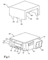
- FIG. 1 is an exploded perspective view (a state before mounting a cover) showing the control unit (including a storage case) .
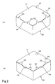
- FIGs. 2A, 2B are perspective views showing states before and after a crimping step of the storage case.
- Fig. 3A is a plan view showing a principal portion of a base.
- Fig. 3B is a cross-sectional side view explaining a positioning step of the storage case.
- Fig. 4A is a side view showing an initial state of the positioning step of the storage case.
- Fig. 4B is a perspective view explaining a state after the storage case is assembled.
- the control unit of this embodiment includes a base 10, a square circuit substrate 20 mounted to the base 10, and a box-shaped cover 30 mounted on the upper surface of the base 10 so as to cover the circuit substrate 20.
- a switching device normally, FET
- PWM pulse width modulation
- the metal substrate 25 is bonded on the base 10, so that heat generated at the switching device is efficiently discharged outside via the base 10.
- Components represented by reference numerals 21, 22 in Fig. 1 are connectors of the circuit substrate 20.
- the base 10 is formed of metal die, for example, of aluminum, and the cover 30 is fabricated by press-cutting processing or deformation processing (deep drawing or bending, etc.) of, for example galvanized sheet iron.
- the base 10 and the cover 30 constitute the storage case of this embodiment.
- the base 10 includes a square plate-shaped substrate member 11 and four leg portions 12 provided at four corners on the upper surface of the substrate member 11 so as to project upward.
- the base 10 includes a guide surface (flange surface) 13 extending in the vertical direction at a position slightly inside a peripheral edge of the upper surface of the substrate member 11.
- the guide surface 13 opposes the inner surface of an opening-side edge 31 of the cover 30 moving to the mounting position with respect to the base 10 with a small clearance and guides the cover 30 to the mounting position.
- the outer peripheries of the leg portions 12 correspond to part of the guide surface 13.
- Rattling-preventing projections 14 which come into abutment with the opening-side edge of the cover 30 positioned at the mounting position from the outside are provided at predetermined position of the peripheral edge of the substrate member 11 (the respective centers of three sides except for the side on which the connectors 21, 22 are to be disposed) . Then, on the inner sides of the rattling-preventing projections 14 bevels 14a are formed for pressing the opening-side edge 31 of the cover 30 to resiliently deform the peripheral wall of the cover 30 inward and bringing a reaction force to act in the direction to cause the cover 30 to move away from the substrate member 11 and be released.from the base 10 as shown in Fig. 3B.
- the shape, being shown in Fig. 3B, is inclined outward when viewed from near the center of the substrate member 11.
- the guide surface 13 is, as shown in Fig. 3A, recessed inwardly on the backside of the rattling-preventing projections 14, whereby a recess 15 is formed.
- the recess 15 serves as a release for enabling inward resilient deformation of the peripheral wall of the cover 30.
- notches 16 are provided on both sides of the rattling-preventing projections 14 on the peripheral edge of the substrate member 11 for disposing (inserting) crimping projections 33, described later, of the cover 30.
- the circuit substrate 20 is secured by screws at four corners with respect to the respective leg portions 12 (not shown) .
- the cover 30 is a box-shaped rectangular solid with an opening lower surface, and is formed at the positions of the peripheral wall thereof where the connectors 21, 22 are to be disposed with notches 32 for avoiding interference with the connectors 21, 22.
- the crimping projections 33 are bent toward the lower surface (rear surface) of the substrate member 11 in a state in which the cover 30 is mounted, so that the cover 30 is retained at the mounting position against the reaction force.
- the peripheral wall of the cover in an assembled state, the peripheral wall of the cover is resiliently deformed inwardly and the reaction force from the rattling-preventing projection 14 (bevel 14a) of the base 10 is exerted to the opening-side edge 31 of the cover in the direction in which the cover 30 moves away from the base 10.
- the crimping projection 33 bent toward the lower surface of the substrate member 11 retains the cover 30 at the mounting position against the reaction force.
- the cover 30 in the assembled state is fixed to the base 10 mainly in a state in which the peripheral wall thereof is resiliently deformed (tensed state) due to a reaction force from the rattling preventing projection 14 described above and a drag by the crimping projection 33, as shown in Fig. 4B. Therefore, rattling (relative displacement of the cover 30 with respect to the base 10) is prevented, whereby abnormal noise, abnormal vibrations, damage of members, etc. caused by the rattling are also prevented.
- the storage case has a structure in which the peripheral wall of the cover is resiliently deformed inwardly by the rattling-preventing projections 14, it is easy to avoid sliding contact between the rattling-preventing projections 14 and the peripheral wall of the cover (opening-side edge of the cover 31) at the time of assembly (when mounting the cover 30 on the base 10).
- generation of chips caused by sliding contact between the rattling-preventing projections and the peripheral wall of the cover (opening-side edge 31 of the cover) can be prevented with high degree of reliability.
- the method of assembling the storage case according to this embodiment includes a positioning step and a crimping step.
- the positioning step includes the steps of positioning the cover 30 in the fore-and-aft direction and lateral direction with respect to the base 10 so that the peripheral wall of the cover 30 is located outside the aforementioned guide surface 13 and the aforementioned crimping projections 33 are located exactly above the notches 16, and, in this state, as shown in Fig. 4A, moving the cover 30 downwardly with respect to the base 10, and moving the cover 30 to the mounting position and positioning the same with respect to the base 10.
- This positioning step includes the steps of moving the cover 30 to the mounting position with respect to the base 10 while avoiding contact (sliding contact) between the opening-side edge 31 of the cover 30 and the rattling-preventing projections 14 by resiliently deforming the opening-side edge 31 of the cover 30 inwardly as shown in Fig. 3A by a chain line by pressing the outer surface of the opening-side edge 31 of the cover 30 from the outside.
- the mounting position means a state in which the cover 30 is moved with respect to the base 10 as described above and the opening-side edge 31 of the cover 30 is bonded to the substrate member 11 of the base 10 (shown in Fig. 2A).
- the crimping step is a step of bending the crimping projections 33 of the cover 30 in a state of being positioned in the positioning step toward the lower surface (back surface) of the substrate member 11 as shown in Fig. 2B.
- the probability of generation of the chips at the time of assembly is very low.
- the operation of pressing the outer surface of the opening-side edge 31 of the cover 30 from the outside may be performed by manpower, but it may also be performed using a machine or a jig.
- a machine having a mechanism to hold the cover 30 and determine the position in the fore-and-aft direction or the lateral direction with respect to the base 10, and then move the cover 30 downward to the mounting position with respect to the base 10, and including rotatable rollers (represented by reference numeral 40 in Fig.
- the above-described positioning step can be implemented automatically with a simple structure only including an actuator for causing the cover 30 to move relatively downward.
- this structure can also prevent sliding contact between the rattling-preventing projections 14 and the peripheral wall (opening-side edge 31) of the cover by pressing the peripheral wall (opening-side edge 31) of the cover, which is moving downward, with the outer peripheral surfaces of the rotating rollers 40, the peripheral wall of the cover is prevented from becoming damaged.
- a pressing state in which the outer surface of the opening-side edge 31 of the cover 30 is pressed from the outside may be released after the positioning step is completed or the crimping step is completed.
- the cover is brought into the state of resiliently deformed to prevent rattling.
- a larger number of rattling-preventing projections or crimping projections may be provided.
Landscapes
- Engineering & Computer Science (AREA)
- Microelectronics & Electronic Packaging (AREA)
- Mechanical Engineering (AREA)
- Casings For Electric Apparatus (AREA)
- Power Steering Mechanism (AREA)
- Steering Controls (AREA)
Abstract
Description
the opening-side edge of the cover is formed with a crimping projection formed by being bent toward the lower surface of the substrate member so as to retain the cover at the mounting position against the reaction force.
a crimping step of bending the crimping projection of the cover in a state of being positioned by the positioning step toward the lower surface of the substrate member.
Claims (2)
- A storage case comprising:wherein rattling-preventing projections are provided at a plurality of positions on a peripheral edge of the substrate member so as to come into abutment with an opening-side edge of the cover, which is positioned at a mounting position with respect to the base, from the outside, the rattling-preventing projections are formed on the inner side thereof with bevels which press the opening-side edge to resiliently deform a peripheral wall of the cover inward and cause a reaction force to act in the direction in which the cover moves away from the substrate member,a base having a plate-shaped substrate member; anda box-shaped cover having an opening on the lower surface and being mounted to the base so as to cover the upper surface of the substrate member,
the opening-side edge of the cover is formed with a crimping projection formed by being bent toward the lower surface of the substrate member so as to retain the cover at the mounting position against the reaction force. - A method of assembling a storage case according to Claim 1 comprising: a positioning step of moving the cover to the mounting position with respect to the base while avoiding contact between the opening-side edge of the cover and the rattling-preventing projections by resiliently deforming the peripheral wall of the cover inwardly by pressing the outer surface of the opening-side edge of the cover from the outside so that the opening-side edge and the rattling-preventing projections are in contact when positioning is completed; and
a crimping step of bending the crimping projection of the cover in a state of being positioned by the positioning step toward the lower surface of the substrate member.
Applications Claiming Priority (2)
| Application Number | Priority Date | Filing Date | Title |
|---|---|---|---|
| JP2004160655A JP4164764B2 (en) | 2004-05-31 | 2004-05-31 | Assembling the storage case |
| JP2004160655 | 2004-05-31 |
Publications (3)
| Publication Number | Publication Date |
|---|---|
| EP1603377A2 true EP1603377A2 (en) | 2005-12-07 |
| EP1603377A3 EP1603377A3 (en) | 2008-05-21 |
| EP1603377B1 EP1603377B1 (en) | 2011-05-18 |
Family
ID=34934254
Family Applications (1)
| Application Number | Title | Priority Date | Filing Date |
|---|---|---|---|
| EP05005519A Expired - Lifetime EP1603377B1 (en) | 2004-05-31 | 2005-03-14 | Storage case and method of assembling the same |
Country Status (6)
| Country | Link |
|---|---|
| US (1) | US7847201B2 (en) |
| EP (1) | EP1603377B1 (en) |
| JP (1) | JP4164764B2 (en) |
| KR (1) | KR100596912B1 (en) |
| CN (1) | CN100444711C (en) |
| AT (1) | ATE509802T1 (en) |
Cited By (4)
| Publication number | Priority date | Publication date | Assignee | Title |
|---|---|---|---|---|
| EP1995121A1 (en) * | 2007-05-21 | 2008-11-26 | Magneti Marelli Powertrain S.p.A. | Electronic control unit with deformable fastening tabs |
| WO2009155900A1 (en) * | 2008-06-28 | 2009-12-30 | Conti Temic Microelectonic Gmbh | Method for producing a tight, form-fitting connection |
| NL1036862A (en) * | 2008-10-20 | 2010-04-21 | Askey Computer Corp | Assembly device. |
| US10932377B2 (en) | 2016-12-20 | 2021-02-23 | Vitesco Technologies Germany Gmbh | Housing for electrical components and method for connecting a housing body to a housing cover |
Families Citing this family (8)
| Publication number | Priority date | Publication date | Assignee | Title |
|---|---|---|---|---|
| KR101887734B1 (en) * | 2015-01-23 | 2018-08-10 | 니혼도꾸슈도교 가부시키가이샤 | Cover attachment structure of case |
| DE102015202316A1 (en) * | 2015-02-10 | 2016-08-11 | Robert Bosch Gmbh | Housing and control unit with a housing |
| WO2017163638A1 (en) * | 2016-03-22 | 2017-09-28 | 富士電機株式会社 | Case, semiconductor device, and method for manufacturing case |
| JP6950326B2 (en) * | 2017-07-25 | 2021-10-13 | 株式会社デンソー | Power converter |
| JP7233208B2 (en) * | 2018-11-30 | 2023-03-06 | 三菱重工サーマルシステムズ株式会社 | refrigeration cycle equipment |
| JP7444093B2 (en) * | 2021-02-03 | 2024-03-06 | 株式会社デンソーエレクトロニクス | housing |
| JP7628901B2 (en) * | 2021-06-23 | 2025-02-12 | ニデックモビリティ株式会社 | Storage case and assembly method |
| DE102024114807A1 (en) * | 2024-05-27 | 2025-11-27 | Valeo Eautomotive Germany Gmbh | Electric drive for a vehicle and corresponding manufacturing process |
Family Cites Families (21)
| Publication number | Priority date | Publication date | Assignee | Title |
|---|---|---|---|---|
| DE3107770A1 (en) * | 1981-02-28 | 1982-09-16 | Robert Bosch Gmbh, 7000 Stuttgart | Electronic controller, especially for motor vehicles |
| JPH0541591Y2 (en) | 1984-10-02 | 1993-10-20 | ||
| JPS6175191U (en) | 1984-10-19 | 1986-05-21 | ||
| US4836408A (en) * | 1987-10-13 | 1989-06-06 | United Technologies Automotive, Inc. | Integral latching arm |
| US5347160A (en) * | 1992-09-28 | 1994-09-13 | Sundstrand Corporation | Power semiconductor integrated circuit package |
| JP2729135B2 (en) * | 1992-12-15 | 1998-03-18 | 新潟日本電気株式会社 | Housing holder |
| JPH07312483A (en) | 1994-05-17 | 1995-11-28 | Mitsubishi Electric Corp | Electronic circuit component housing case |
| JP2924681B2 (en) * | 1994-12-28 | 1999-07-26 | 住友電装株式会社 | Electrical junction box |
| JPH09181461A (en) * | 1995-12-21 | 1997-07-11 | Denshi Giken:Kk | Component housing case |
| JPH1075072A (en) * | 1996-08-30 | 1998-03-17 | Hitachi Ltd | Electronic component storage case |
| JP2978120B2 (en) * | 1996-09-20 | 1999-11-15 | 富士通テン株式会社 | Fitting structure of case and lid |
| US5872332A (en) * | 1997-06-27 | 1999-02-16 | Delco Electronics Corp. | Molded housing with EMI shield |
| JP2000013042A (en) * | 1998-06-23 | 2000-01-14 | Harness Syst Tech Res Ltd | Electronic unit case |
| DE19921928C2 (en) * | 1999-05-12 | 2002-11-14 | Bosch Gmbh Robert | Electric device |
| DE10045728B4 (en) * | 1999-09-17 | 2015-08-20 | Denso Corporation | Housing for an electronic control unit and arrangement of such a housing and an electronic circuit unit |
| US6717051B2 (en) * | 2001-02-21 | 2004-04-06 | Denso Corporation | Electronic control unit for use in automotive vehicle |
| JP2002344157A (en) * | 2001-05-17 | 2002-11-29 | Kenwood Corp | Mounting structure of chassis and top panel |
| JP3906064B2 (en) * | 2001-11-26 | 2007-04-18 | 三洋電機株式会社 | Mounting structure of metal cover to chassis |
| JP2004032960A (en) * | 2002-06-28 | 2004-01-29 | Yazaki Corp | Electrical junction box and its manufacturing method |
| JP2004152831A (en) * | 2002-10-29 | 2004-05-27 | Fujitsu Access Ltd | Cabinet |
| JP4263139B2 (en) * | 2004-06-07 | 2009-05-13 | アルプス電気株式会社 | Mounting structure for in-vehicle electronic circuit unit |
-
2004
- 2004-05-31 JP JP2004160655A patent/JP4164764B2/en not_active Expired - Fee Related
-
2005
- 2005-03-14 AT AT05005519T patent/ATE509802T1/en not_active IP Right Cessation
- 2005-03-14 EP EP05005519A patent/EP1603377B1/en not_active Expired - Lifetime
- 2005-03-22 KR KR1020050023583A patent/KR100596912B1/en not_active Expired - Fee Related
- 2005-04-06 CN CNB2005100648284A patent/CN100444711C/en not_active Expired - Fee Related
- 2005-05-26 US US11/138,131 patent/US7847201B2/en not_active Expired - Fee Related
Cited By (5)
| Publication number | Priority date | Publication date | Assignee | Title |
|---|---|---|---|---|
| EP1995121A1 (en) * | 2007-05-21 | 2008-11-26 | Magneti Marelli Powertrain S.p.A. | Electronic control unit with deformable fastening tabs |
| WO2009155900A1 (en) * | 2008-06-28 | 2009-12-30 | Conti Temic Microelectonic Gmbh | Method for producing a tight, form-fitting connection |
| US8584340B2 (en) | 2008-06-28 | 2013-11-19 | Conti Temic Microelectronic Gmbh | Method for producing a tight, form-fitting connection |
| NL1036862A (en) * | 2008-10-20 | 2010-04-21 | Askey Computer Corp | Assembly device. |
| US10932377B2 (en) | 2016-12-20 | 2021-02-23 | Vitesco Technologies Germany Gmbh | Housing for electrical components and method for connecting a housing body to a housing cover |
Also Published As
| Publication number | Publication date |
|---|---|
| US20050263529A1 (en) | 2005-12-01 |
| KR100596912B1 (en) | 2006-07-05 |
| CN1705430A (en) | 2005-12-07 |
| EP1603377A3 (en) | 2008-05-21 |
| CN100444711C (en) | 2008-12-17 |
| JP2005340700A (en) | 2005-12-08 |
| ATE509802T1 (en) | 2011-06-15 |
| US7847201B2 (en) | 2010-12-07 |
| KR20060044538A (en) | 2006-05-16 |
| EP1603377B1 (en) | 2011-05-18 |
| JP4164764B2 (en) | 2008-10-15 |
Similar Documents
| Publication | Publication Date | Title |
|---|---|---|
| US7847201B2 (en) | Storage case and method of assembling the same | |
| US8213182B2 (en) | Housing case for housing electronic circuit board, and electronic apparatus | |
| US7559784B2 (en) | IC socket | |
| US8992269B2 (en) | Connecting device for a solar module | |
| EP3329557B1 (en) | Modular connector | |
| EP1760627B1 (en) | Memory card socket | |
| JP2006503409A (en) | Pressure actuated electric blister switch and method for manufacturing the switch | |
| JP5878101B2 (en) | Electronic control unit | |
| US5712766A (en) | One-piece housing and interlocking connector for IC card assemblies | |
| WO2019159691A1 (en) | Connector | |
| KR20190026915A (en) | Connection element | |
| US20210059041A1 (en) | Holder For Thermally Contacting An Electronic Component Mounted On A Circuit Board And A Cooling Body | |
| CN210379280U (en) | Horizontal press-fitting device for battery | |
| JP2002246767A (en) | Electronic control equipment case and electronic control equipment | |
| JP3399733B2 (en) | Terminal structure of lead-acid battery | |
| JP4314524B2 (en) | Storage case | |
| JP2000188491A (en) | Board holding structure | |
| JP7628901B2 (en) | Storage case and assembly method | |
| JP7579307B2 (en) | Terminal connection structure | |
| JP6610502B2 (en) | Junction box manufacturing method | |
| JP2000036558A (en) | Lead frame and manufacturing method thereof | |
| US20220059969A1 (en) | Substrate protection structure during inner housing assembling | |
| JPH10256773A (en) | Noise absorber | |
| US20210367304A1 (en) | Combination of container and mountable component, and container | |
| JP2594749Y2 (en) | Magnetic disk drive |
Legal Events
| Date | Code | Title | Description |
|---|---|---|---|
| PUAI | Public reference made under article 153(3) epc to a published international application that has entered the european phase |
Free format text: ORIGINAL CODE: 0009012 |
|
| AK | Designated contracting states |
Kind code of ref document: A2 Designated state(s): AT BE BG CH CY CZ DE DK EE ES FI FR GB GR HU IE IS IT LI LT LU MC NL PL PT RO SE SI SK TR |
|
| AX | Request for extension of the european patent |
Extension state: AL BA HR LV MK YU |
|
| PUAL | Search report despatched |
Free format text: ORIGINAL CODE: 0009013 |
|
| AK | Designated contracting states |
Kind code of ref document: A3 Designated state(s): AT BE BG CH CY CZ DE DK EE ES FI FR GB GR HU IE IS IT LI LT LU MC NL PL PT RO SE SI SK TR |
|
| AX | Request for extension of the european patent |
Extension state: AL BA HR LV MK YU |
|
| RIC1 | Information provided on ipc code assigned before grant |
Ipc: B60R 16/02 20060101AFI20080411BHEP Ipc: H05K 5/00 20060101ALI20080411BHEP |
|
| RIN1 | Information on inventor provided before grant (corrected) |
Inventor name: FUKUMOTO, TETSUYA,C/O OMRON CORPORATION Inventor name: YASUDA, TAKESHI,C/O OMRON CORPORATION Inventor name: SAITO, TOSHIO,C/O OMRON CORPORATION Inventor name: KADOGAKI, KAZUSHI,C/O OMRON CORPORATION |
|
| 17P | Request for examination filed |
Effective date: 20081009 |
|
| AKX | Designation fees paid |
Designated state(s): AT BE BG CH CY CZ DE DK EE ES FI FR GB GR HU IE IS IT LI LT LU MC NL PL PT RO SE SI SK TR |
|
| RAP1 | Party data changed (applicant data changed or rights of an application transferred) |
Owner name: OMRON AUTOMOTIVE ELECTRONICS CO., LTD. |
|
| GRAP | Despatch of communication of intention to grant a patent |
Free format text: ORIGINAL CODE: EPIDOSNIGR1 |
|
| GRAS | Grant fee paid |
Free format text: ORIGINAL CODE: EPIDOSNIGR3 |
|
| GRAA | (expected) grant |
Free format text: ORIGINAL CODE: 0009210 |
|
| AK | Designated contracting states |
Kind code of ref document: B1 Designated state(s): AT BE BG CH CY CZ DE DK EE ES FI FR GB GR HU IE IS IT LI LT LU MC NL PL PT RO SE SI SK TR |
|
| REG | Reference to a national code |
Ref country code: GB Ref legal event code: FG4D |
|
| REG | Reference to a national code |
Ref country code: CH Ref legal event code: EP |
|
| REG | Reference to a national code |
Ref country code: IE Ref legal event code: FG4D |
|
| REG | Reference to a national code |
Ref country code: DE Ref legal event code: R096 Ref document number: 602005028067 Country of ref document: DE Effective date: 20110630 |
|
| REG | Reference to a national code |
Ref country code: NL Ref legal event code: VDEP Effective date: 20110518 |
|
| PG25 | Lapsed in a contracting state [announced via postgrant information from national office to epo] |
Ref country code: SE Free format text: LAPSE BECAUSE OF FAILURE TO SUBMIT A TRANSLATION OF THE DESCRIPTION OR TO PAY THE FEE WITHIN THE PRESCRIBED TIME-LIMIT Effective date: 20110518 Ref country code: LT Free format text: LAPSE BECAUSE OF FAILURE TO SUBMIT A TRANSLATION OF THE DESCRIPTION OR TO PAY THE FEE WITHIN THE PRESCRIBED TIME-LIMIT Effective date: 20110518 Ref country code: PT Free format text: LAPSE BECAUSE OF FAILURE TO SUBMIT A TRANSLATION OF THE DESCRIPTION OR TO PAY THE FEE WITHIN THE PRESCRIBED TIME-LIMIT Effective date: 20110919 |
|
| PG25 | Lapsed in a contracting state [announced via postgrant information from national office to epo] |
Ref country code: ES Free format text: LAPSE BECAUSE OF FAILURE TO SUBMIT A TRANSLATION OF THE DESCRIPTION OR TO PAY THE FEE WITHIN THE PRESCRIBED TIME-LIMIT Effective date: 20110829 Ref country code: BE Free format text: LAPSE BECAUSE OF FAILURE TO SUBMIT A TRANSLATION OF THE DESCRIPTION OR TO PAY THE FEE WITHIN THE PRESCRIBED TIME-LIMIT Effective date: 20110518 Ref country code: CY Free format text: LAPSE BECAUSE OF FAILURE TO SUBMIT A TRANSLATION OF THE DESCRIPTION OR TO PAY THE FEE WITHIN THE PRESCRIBED TIME-LIMIT Effective date: 20110518 Ref country code: IS Free format text: LAPSE BECAUSE OF FAILURE TO SUBMIT A TRANSLATION OF THE DESCRIPTION OR TO PAY THE FEE WITHIN THE PRESCRIBED TIME-LIMIT Effective date: 20110918 Ref country code: FI Free format text: LAPSE BECAUSE OF FAILURE TO SUBMIT A TRANSLATION OF THE DESCRIPTION OR TO PAY THE FEE WITHIN THE PRESCRIBED TIME-LIMIT Effective date: 20110518 Ref country code: GR Free format text: LAPSE BECAUSE OF FAILURE TO SUBMIT A TRANSLATION OF THE DESCRIPTION OR TO PAY THE FEE WITHIN THE PRESCRIBED TIME-LIMIT Effective date: 20110819 Ref country code: AT Free format text: LAPSE BECAUSE OF FAILURE TO SUBMIT A TRANSLATION OF THE DESCRIPTION OR TO PAY THE FEE WITHIN THE PRESCRIBED TIME-LIMIT Effective date: 20110518 Ref country code: SI Free format text: LAPSE BECAUSE OF FAILURE TO SUBMIT A TRANSLATION OF THE DESCRIPTION OR TO PAY THE FEE WITHIN THE PRESCRIBED TIME-LIMIT Effective date: 20110518 |
|
| PG25 | Lapsed in a contracting state [announced via postgrant information from national office to epo] |
Ref country code: NL Free format text: LAPSE BECAUSE OF FAILURE TO SUBMIT A TRANSLATION OF THE DESCRIPTION OR TO PAY THE FEE WITHIN THE PRESCRIBED TIME-LIMIT Effective date: 20110518 |
|
| PG25 | Lapsed in a contracting state [announced via postgrant information from national office to epo] |
Ref country code: CZ Free format text: LAPSE BECAUSE OF FAILURE TO SUBMIT A TRANSLATION OF THE DESCRIPTION OR TO PAY THE FEE WITHIN THE PRESCRIBED TIME-LIMIT Effective date: 20110518 Ref country code: EE Free format text: LAPSE BECAUSE OF FAILURE TO SUBMIT A TRANSLATION OF THE DESCRIPTION OR TO PAY THE FEE WITHIN THE PRESCRIBED TIME-LIMIT Effective date: 20110518 |
|
| PG25 | Lapsed in a contracting state [announced via postgrant information from national office to epo] |
Ref country code: SK Free format text: LAPSE BECAUSE OF FAILURE TO SUBMIT A TRANSLATION OF THE DESCRIPTION OR TO PAY THE FEE WITHIN THE PRESCRIBED TIME-LIMIT Effective date: 20110518 Ref country code: PL Free format text: LAPSE BECAUSE OF FAILURE TO SUBMIT A TRANSLATION OF THE DESCRIPTION OR TO PAY THE FEE WITHIN THE PRESCRIBED TIME-LIMIT Effective date: 20110518 Ref country code: RO Free format text: LAPSE BECAUSE OF FAILURE TO SUBMIT A TRANSLATION OF THE DESCRIPTION OR TO PAY THE FEE WITHIN THE PRESCRIBED TIME-LIMIT Effective date: 20110518 Ref country code: DK Free format text: LAPSE BECAUSE OF FAILURE TO SUBMIT A TRANSLATION OF THE DESCRIPTION OR TO PAY THE FEE WITHIN THE PRESCRIBED TIME-LIMIT Effective date: 20110518 |
|
| PLBE | No opposition filed within time limit |
Free format text: ORIGINAL CODE: 0009261 |
|
| STAA | Information on the status of an ep patent application or granted ep patent |
Free format text: STATUS: NO OPPOSITION FILED WITHIN TIME LIMIT |
|
| 26N | No opposition filed |
Effective date: 20120221 |
|
| PG25 | Lapsed in a contracting state [announced via postgrant information from national office to epo] |
Ref country code: IT Free format text: LAPSE BECAUSE OF FAILURE TO SUBMIT A TRANSLATION OF THE DESCRIPTION OR TO PAY THE FEE WITHIN THE PRESCRIBED TIME-LIMIT Effective date: 20110518 |
|
| REG | Reference to a national code |
Ref country code: DE Ref legal event code: R097 Ref document number: 602005028067 Country of ref document: DE Effective date: 20120221 |
|
| PGFP | Annual fee paid to national office [announced via postgrant information from national office to epo] |
Ref country code: GB Payment date: 20120314 Year of fee payment: 8 |
|
| PG25 | Lapsed in a contracting state [announced via postgrant information from national office to epo] |
Ref country code: MC Free format text: LAPSE BECAUSE OF NON-PAYMENT OF DUE FEES Effective date: 20120331 |
|
| REG | Reference to a national code |
Ref country code: CH Ref legal event code: PL |
|
| REG | Reference to a national code |
Ref country code: IE Ref legal event code: MM4A |
|
| PG25 | Lapsed in a contracting state [announced via postgrant information from national office to epo] |
Ref country code: IE Free format text: LAPSE BECAUSE OF NON-PAYMENT OF DUE FEES Effective date: 20120314 Ref country code: LI Free format text: LAPSE BECAUSE OF NON-PAYMENT OF DUE FEES Effective date: 20120331 Ref country code: CH Free format text: LAPSE BECAUSE OF NON-PAYMENT OF DUE FEES Effective date: 20120331 |
|
| PG25 | Lapsed in a contracting state [announced via postgrant information from national office to epo] |
Ref country code: BG Free format text: LAPSE BECAUSE OF FAILURE TO SUBMIT A TRANSLATION OF THE DESCRIPTION OR TO PAY THE FEE WITHIN THE PRESCRIBED TIME-LIMIT Effective date: 20110818 |
|
| GBPC | Gb: european patent ceased through non-payment of renewal fee |
Effective date: 20130314 |
|
| PG25 | Lapsed in a contracting state [announced via postgrant information from national office to epo] |
Ref country code: GB Free format text: LAPSE BECAUSE OF NON-PAYMENT OF DUE FEES Effective date: 20130314 |
|
| PG25 | Lapsed in a contracting state [announced via postgrant information from national office to epo] |
Ref country code: TR Free format text: LAPSE BECAUSE OF FAILURE TO SUBMIT A TRANSLATION OF THE DESCRIPTION OR TO PAY THE FEE WITHIN THE PRESCRIBED TIME-LIMIT Effective date: 20110518 |
|
| PG25 | Lapsed in a contracting state [announced via postgrant information from national office to epo] |
Ref country code: LU Free format text: LAPSE BECAUSE OF NON-PAYMENT OF DUE FEES Effective date: 20120314 |
|
| PG25 | Lapsed in a contracting state [announced via postgrant information from national office to epo] |
Ref country code: HU Free format text: LAPSE BECAUSE OF FAILURE TO SUBMIT A TRANSLATION OF THE DESCRIPTION OR TO PAY THE FEE WITHIN THE PRESCRIBED TIME-LIMIT Effective date: 20050314 |
|
| REG | Reference to a national code |
Ref country code: DE Ref legal event code: R084 Ref document number: 602005028067 Country of ref document: DE Effective date: 20140717 |
|
| REG | Reference to a national code |
Ref country code: FR Ref legal event code: PLFP Year of fee payment: 11 |
|
| PGFP | Annual fee paid to national office [announced via postgrant information from national office to epo] |
Ref country code: DE Payment date: 20150310 Year of fee payment: 11 |
|
| PGFP | Annual fee paid to national office [announced via postgrant information from national office to epo] |
Ref country code: FR Payment date: 20150309 Year of fee payment: 11 |
|
| REG | Reference to a national code |
Ref country code: DE Ref legal event code: R119 Ref document number: 602005028067 Country of ref document: DE |
|
| REG | Reference to a national code |
Ref country code: FR Ref legal event code: ST Effective date: 20161130 |
|
| PG25 | Lapsed in a contracting state [announced via postgrant information from national office to epo] |
Ref country code: DE Free format text: LAPSE BECAUSE OF NON-PAYMENT OF DUE FEES Effective date: 20161001 Ref country code: FR Free format text: LAPSE BECAUSE OF NON-PAYMENT OF DUE FEES Effective date: 20160331 |