EP1603308A1 - Display cover for a communication device - Google Patents
Display cover for a communication device Download PDFInfo
- Publication number
- EP1603308A1 EP1603308A1 EP04102445A EP04102445A EP1603308A1 EP 1603308 A1 EP1603308 A1 EP 1603308A1 EP 04102445 A EP04102445 A EP 04102445A EP 04102445 A EP04102445 A EP 04102445A EP 1603308 A1 EP1603308 A1 EP 1603308A1
- Authority
- EP
- European Patent Office
- Prior art keywords
- cover
- opening
- speaker
- cavity
- acoustic cavity
- Prior art date
- Legal status (The legal status is an assumption and is not a legal conclusion. Google has not performed a legal analysis and makes no representation as to the accuracy of the status listed.)
- Granted
Links
Images


Classifications
-
- H—ELECTRICITY
- H04—ELECTRIC COMMUNICATION TECHNIQUE
- H04M—TELEPHONIC COMMUNICATION
- H04M1/00—Substation equipment, e.g. for use by subscribers
- H04M1/02—Constructional features of telephone sets
- H04M1/0202—Portable telephone sets, e.g. cordless phones, mobile phones or bar type handsets
- H04M1/026—Details of the structure or mounting of specific components
- H04M1/0266—Details of the structure or mounting of specific components for a display module assembly
-
- H—ELECTRICITY
- H04—ELECTRIC COMMUNICATION TECHNIQUE
- H04M—TELEPHONIC COMMUNICATION
- H04M1/00—Substation equipment, e.g. for use by subscribers
- H04M1/02—Constructional features of telephone sets
- H04M1/03—Constructional features of telephone transmitters or receivers, e.g. telephone hand-sets
- H04M1/035—Improving the acoustic characteristics by means of constructional features of the housing, e.g. ribs, walls, resonating chambers or cavities
Definitions
- the invention relates to a cover for a display, in particular a display cover of a communication device, such as a portable phone.
- Typical voice communication devices such as cellular phones, have a receiver (speaker) located at a top portion of the device and a transducer (microphone) located at the bottom portion.
- US 6321070 discloses a portable electronic device with a speaker assembly and a housing and is configured to carry at least one receiver and transmitter.
- a speaker has a front side acoustically coupled to a first air space in front of an ear placement region of part of the housing and has a cover formed from the housing.
- the speaker has a rear side acoustically coupled to a second airspace.
- a cover for a display device for a communication device comprises: external dimensions shaped to fit the cover in a case for the communication device; a top surface; a bottom surface; a non-opaque region to cover the display device allowing a user to see the display device; and a region defining a top of an enclosure cavity for a speaker associated with the communication device.
- the cover may have at least one sound hole located about the region.
- the sound hole extends from the top surface through the cover to the bottom surface and connects to the enclosure cavity.
- the region may have a recess extending inwardly from the top surface into the cover.
- a second cover may be provided to fit over the region. The second cover is shaped to allow passage of air from above the cover to the sound hole.
- an enclosure system for a communication device comprising a case for enclosing elements of the communication device.
- the case has an opening for a display for the device in a first region and a structure to support a speaker for the device in a second region.
- the enclosure has a cover adapted to mate with the case.
- the cover has a top surface; a bottom surface; a non-opaque region adapted to cover the display device allowing a user to see the display device; and a support region for defining a top enclosure for a speaker associated with the device.
- the cover may have at least one sound hole located in a region about the second region. The hole extends from the top surface through the cover to the bottom surface.
- the system may have a second cover shaped to fit into the region and shaped to allow air access to the at least one sound hole from above the cover.
- the case may have at least one cavity located about the structure; an air channel to connect the cavity to the second region, such that the cavity is shaped to provide acoustic tuning for the speaker.
- a handheld communication device comprising: speaker; a display device; a housing having an opening to allow viewing of the display device therethrough; a second opening to allow placement of the speaker therein; and a cover being fixedly mountable to the housing.
- the cover has a first portion for covering the display device and a second portion adapted to acoustically transmit sound from the speaker.
- the first portion may comprise a non-opaque region adapted to cover the display device.
- Said device may further comprise a second cover shaped to fit into the region and shaped to allow air access to the at least one sound hole from above the cover.
- the housing may further have a first cavity to provide acoustic tuning for the speaker, and an air channel connecting the first cavity to a region above the speaker.
- the first cavity may span both sides of the second opening.
- the housing may further have a second cavity to provide acoustic tuning for the speaker, and a second air channel connecting the second cavity to a region below the speaker.
- the second cavity may span both sides of the second opening.
- the housing may further have a third cavity to provide acoustic tuning for the speaker in combination with the first and the second cavities, and a third air channel connecting the second and third cavities.
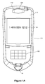
- Figure 1A is a top plan view of a communication device associated with an embodiment of the invention.
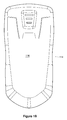
- Figure 1B is a bottom plan view of the communication device of Fig. 1A;
- Figure 2 is a top exploded perspective view of selected internal components and a case section of the communication device of Figs. 1A and 1B;
- Figure 3 is a top plan view of the case section of the communication device of Fig. 2;
- Figure 4 is a bottom exploded perspective view of the selected internal components and the case section of Fig. 2.
- communication device 100 provides voice communications with other devices, allowing the user to hear audio signals (e.g. voices) transmitted from another device (e.g. a cellular phone).
- Device 100 may be a telephone, a cordless telephone, a cellular telephone, a voice-enabled personal digital assistant (PDA) or any other voice communication device. Communications may be provided via wireless systems, wired systems or a combination of both systems.
- PDA personal digital assistant
- device 100 has a keypad 102, display 104, microphone 106 and transducer 108, i.e. speaker 108 all contained within an enclosure.
- Display 104 is an LCD device.
- Display cover 110 provides a transparent, translucent or non-opaque physical cover for the viewing area of display 104 and extends beyond it.
- Speaker cover 112 covers a recess in display cover 110. The recess is located above the installation location of speaker 108.
- Case 114 provides a physical enclosure for the electronics and mechanical elements for device 100. Back of case 114 is shown in Fig. 1B as bottom case section 116. General internal circuits and operations of device 100 are well known in the art and are not provided here.
- Device 100 provides voice communications for a user in a familiar interface. To initiate a call, the user activates device 100, enters a telephone number to be called on keypad 102 and initiates the call. After the call is connected, the user places device 100 about his mouth and one of his ears, such that microphone 106 is near his mouth and speaker 108 is near his ear. User speaks towards microphone 106 and listens for sounds from the called party through speaker 108.
- view 200 provides an exploded top perspective view of internal and external elements in an upper portion of device 100.
- case 114 is comprised of top case section 202 and bottom case section 116 (Fig. 1B).
- Top case section 202 provides a one-piece cover for internal elements of device 100.
- Top case section 202 mates with bottom case section 116 along their respective sides.
- Various dimensions and fitting interfaces between top case section 202 and bottom case section 116 may be provided in other embodiments, including those known in the art.
- alternative top and bottom case sections may generally have an exterior form as described in U.S. Design Patent D479,233, which is incorporated herein by reference.
- top case section 202 is shaped to define the front face of device 100 and the top portion of the exterior edge of case 114. Top section 202 also provides internal bracing for structural support for device 100 and has two openings in its front face: opening 204 allows access to keypad 102 and opening 206 allows viewing of LCD 104. Top case section 202 is preferably a plastic moulded injected casing.
- Display area of LCD 104 is covered by display cover 110; however, display cover 110 further extends upwardly above LCD 104 to the top edge of case section 202. As such, display cover 110 provides a single seamless structure to cover both LCD 104 and speaker 108. Accordingly, case section 202 does not have to provide a top cover for speaker 108.
- display cover 110 may be silk screened with custom lettering or graphics around display area of LCD 104 and around the area where speaker 108 is located.
- display cover 110 may be made of almost any material (such as plastic), as long as the material facilitates accurate manufacturing of display cover 110 and provides a transparent, translucent or non-opaque region where display 104 will be placed underneath.
- recess 208 is provided, which is a shaped contour extending inwardly within display cover 110.
- recess 208 is a hexagonal polygon depression having a generally stunted-hexagonal shape.
- the floor of recess 208 is generally flat.
- the exterior edges of recess 208 are bevelled downward to the floor.
- other shapes may be provided for a recess.
- Recess 208 has four sound holes 210 therein which provide air conduits through display cover 110. As such, holes 210 allow passage of acoustic energy from speaker 108 through display cover 110 to the ambient environment outside device 100.
- Two sounds holes 210 are located in the upper and lower corners of the left side of recess 208, a third sound hole 210 is located in the upper corner of the right side of recess 208, and the fourth sound hole 210 is located in the upper area about the center of the recess 208.
- a sound hole has acoustics properties determined, in part, by its dimensions, including its diameter (i.e. cross-sectional area) and length (i.e. thickness of display cover 110 in recess area 208).
- sound holes 210 are cylindrical in shape with round openings. Other shapes and cross sections may be used. While both dimensions are important for acoustic purposes, it is possible to adjust them together to achieve a particular acoustic characteristic.
- the device may have other systems to port the sound energy from its speaker, thereby eliminating a need for sound holes.
- Speaker cover 112 is shaped to fit within recess 208. As such in the embodiment, cover 112 is a stunted hexagonal shape. Speaker cover 112 provides a cover for sound holes 210, thereby enhancing the aesthetic appearance of display cover 110. Speaker cover 112 comprises upper section 212 and lower section 214. The bottom surface of lower portion 214 fits snugly against the upper surface of recess 208. The shape of upper section 212 and lower section 214 provide a corresponding excised notch where each sound hole 210 is located, to allow sound to emit from sound holes 210 into the ambient environment of device 100.
- speaker cover 112 has an inward ridge which is shaped to provide a gap between speaker cover 112 and the bevelled edge of recess 208, when speaker cover 112 is located in recess 208.
- Speaker cover 112 also has nubs thereon protruding downward from its bottom surface. Within recess 208, corresponding concave depressions in locations opposite of the nubs are provided. Nubs 216 in speaker cover 112 fit cooperatively within depressions in recess 208 to assist in aligning speaker cover 112 within recess 208.
- speaker cover 112 has a thickness such that when it is placed in recess 208, its upper surface is either flush or roughly flush with the top surface of cover 110.
- no recess is provided for the sound holes. Further, in other embodiments no cover is provided.
- adhesive display cover tape 218 is provided and is located between LCD 104 and display cover 110.
- Display cover tape 218 has double-sided adhesive thereon to affix its top surface to the bottom surface of display cover 110 and to affix its bottom surface to the top surface of case section 202.
- Display cover tape 218 is excised in area 220 so as to not obstruct view of LCD 104.
- cover tape 218 is black, which enhances concealing of plastics elements beneath it and outlining of the display area of LCD 104.
- Display cover tape 218 has a transparent layer attached in area 220. After attaching tape 218 to display cover 110, the transparent layer is removed using a pull tab.
- Holes 219 and 219A are provided in tape 218 to allow continuity for an air channel between holes 210 and the interior of device 100.
- Hole 219A is an oblong opening and it located to be in line with sound hole 210 located in the upper middle region of recess 208.
- Four holes 219 are provided in a symmetric pattern about hole 219A to provide openings for the three sound holes 210 located on the exterior ends of recess 208.
- tape 218 has a symmetric orientation of holes 219 thereon. As such, if tape 218 is placed either face up or face down over case section 202, one hole 219 will align with one sound hole 210.
- Speaker 108 is located in case section 202 in upper region 222 of case section 202.
- Upper region 222 is generally underneath recess 208 and is bounded by internal structures in case section 202. Such structures include top wall 224, bottom wall 226 and side walls 228.
- the top surface of speaker 108 abuts against an internal lip at the top edge of walls 224, 226 and 228 to precisely provide an installed location for speaker 108 within region 222.
- the external dimensions of upper region 222 are provided to allow speaker 108 to fit snugly therein.
- speaker 108 is mated to a rubber boot to assist in securely holding speaker 108 within upper region 222 and to block acoustic leaks around it.
- Speaker seal 230 is provided to provide an acoustic seal in a cavity around speaker 108. It is located underneath speaker 108. Speaker seal 230 has opening 232 to allow electrical contacts of speaker 108 to engage with a PCB below it (not shown). Further detail on speaker seal 230 is provided below.
- two acoustics cavities are provided around speaker 108 and upper region 222.
- a front cavity located above speaker 108 and sound holes 210 define a Helmholtz resonator to tune high frequencies of speaker 108.
- a back cavity is located behind speaker 108 and provides tuning for its lower frequency response.
- the front cavity is defined in case section 202 by a volume including L-shaped cavity 232 and oblong cavity 234 and its sides and bottom surfaces are defined within case section 202.
- L-shaped cavity 232 and oblong cavity 234 are located immediately to the right and left of region 222, respectively.
- Notches 236 in side walls 228 connect L-shaped cavity 232 and oblong cavity 234 to a volume above speaker 108 to create a continuous volume for the front cavity.
- the bottom of the front cavity is defined by moulded floors in L-shaped cavity 232 and in oblong cavity 234 and by the top surface of speaker 108.
- the top of the front cavity is defined by the bottom surface of display cover tape 218.
- tape 218 provides an acoustic seal between cover 110 and case section 202. It will be appreciated that display cover 110 provides additional structural support for the top of the front cavity. It will be appreciated that having a single piece to cover both display 104 and speaker 108 also provides a cost-effective component for device 100, as its part count is reduced.
- the back cavity is defined in case section 202 by a volume including: box cavity 238, located immediately to the left of region 222; L-shaped cavity 240, located immediately to the right of region 222; and a volume directly beneath speaker 108.
- the sides and top surfaces are defined within case section 202.
- the top boundary of the back cavity is defined by the surface underneath floor of oblong cavity 234, the surface underneath floor of L-shaped cavity 232 and the bottom surface of speaker 108.
- the perimeter of the back cavity is defined by bottom wall 226 and the collective perimeters of box cavity 238, L-shaped cavity 240 and speaker 108.
- the perimeter is comprised in part by lower wall 224 and other wall extrusions descending inwardly from top wall 224.
- the perimeter is defined by the shape of L-shaped cavity 240, speaker 108 and box cavity 238.
- the bottom boundary of the back cavity is defined by bottom edge 242 of the perimeter defined by the end of lower wall 224 and the end of the other wall extrusions.
- Seal 230 is shaped to cover the perimeter defined by bottom edge 242 and fits snugly thereagainst. When device 100 is fully assembled, its PCB (not shown) is snugly fit against seal 230 and its PCB defines the bottom wall of the back cavity.
- bleed hole 246 is located in the ceiling of box cavity 238 and provides an air connection to an intermediate cavity 248 located about the front cavity.
- intermediate cavity 248 is located in a front portion of case section 202 and its sides and bottom surfaces are defined within case section 202.
- Intermediate cavity 248 provides a port through display cover 110 via sound hole 210 located in the upper left of the recessed area 208.
- Bleed hole 246, intermediate cavity 248 and sound ports 210 provides further tuning of the acoustics using the front and back cavities.
- the size, shape and location of a bleed hole can be modified relative to the top and back cavities to effect different acoustic tuning characteristics.
- the top of the intermediate front cavity 248 is defined by the bottom surface of display cover tape 218.
- tape 218 provides an acoustic seal between cover 110 and case section 202. It will be appreciated that display cover 110 provides additional structural support for the top of the intermediate cavity.
- adhesive tape 218 provides an acoustic seal so that sounds from internal cavity 248 do not leak into any of upper region 222, L-shaped cavity 232 and oblong cavity 234.
- the front cavity and intermediate cavity 248 are isolated from each other.
- the location and dimension of their respective sound holes 210 in case section 202 and holes 219 in tape 218 are preferably made such that for each cavity, its associated sound hole 210 and hole 219 do not overlap with the either of the sound hole 210 or the hole 219 for the other cavity.
- display cover 110 forms part of the front cavity and part of intermediate cavity 248.
- display cover 110 forms part of the front cavity and part of intermediate cavity 248.
- the embodiment also has a small hole (not shown), approximately 0.75 mm diameter, through the PCB directly behind speaker 108.
- the hole is used to further tune the frequency response for speaker 108.
- the hole is covered with an acoustic mesh (e.g. a woven polyester material) to provide acoustic resistance and control resonance characteristics of the hole.
- acoustic mesh e.g. a woven polyester material
- Other types of mesh may be used or smaller holes could be drilled in the PCB to produce different acoustic characteristics.
- mesh may be placed over one or more of sound holes 210.
- a nearly acoustically transparent mesh i.e., a mesh having a very low acoustic resistance
- Other embodiments may use other shapes for their front and back cavities and may dispense with one or both of the cavities.
- display cover 110 is generally rectangular, in other embodiments, the display cover can be any shape and size, as long as it covers both the display region and the speaker of the communication device. Further, if the display and the speaker are not on the same face of a device, the display cover can be shaped to bend at the interface line between the two faces and cover both the display and the speaker.
Abstract
Description
- The invention relates to a cover for a display, in particular a display cover of a communication device, such as a portable phone.
- Typical voice communication devices, such as cellular phones, have a receiver (speaker) located at a top portion of the device and a transducer (microphone) located at the bottom portion.
- In designing a communication device, the speaker must be mounted within an enclosure. Typically, the enclosure is a plastic injection moulded piece. To fix the speaker within the enclosure, the top of the enclosure is frequently designed to provide a cover for the speaker. However, this approach limits aesthetic possibilities for the device as there are limitations to colour and texture treatments available for plastics typically used in casings. US 6321070 discloses a portable electronic device with a speaker assembly and a housing and is configured to carry at least one receiver and transmitter. A speaker has a front side acoustically coupled to a first air space in front of an ear placement region of part of the housing and has a cover formed from the housing. The speaker has a rear side acoustically coupled to a second airspace.
- There is a need for a display cover which provides an improvement over the prior art.
- In a first aspect, a cover for a display device for a communication device is provided. The cover comprises: external dimensions shaped to fit the cover in a case for the communication device; a top surface; a bottom surface; a non-opaque region to cover the display device allowing a user to see the display device; and a region defining a top of an enclosure cavity for a speaker associated with the communication device.
- The cover may have at least one sound hole located about the region. The sound hole extends from the top surface through the cover to the bottom surface and connects to the enclosure cavity.
- In the cover, the region may have a recess extending inwardly from the top surface into the cover. Further, a second cover may be provided to fit over the region. The second cover is shaped to allow passage of air from above the cover to the sound hole.
- In a second aspect, an enclosure system for a communication device is provided. The enclosure comprises a case for enclosing elements of the communication device. The case has an opening for a display for the device in a first region and a structure to support a speaker for the device in a second region. The enclosure has a cover adapted to mate with the case. The cover has a top surface; a bottom surface; a non-opaque region adapted to cover the display device allowing a user to see the display device; and a support region for defining a top enclosure for a speaker associated with the device.
- In the system, the cover may have at least one sound hole located in a region about the second region. The hole extends from the top surface through the cover to the bottom surface.
- The system may have a second cover shaped to fit into the region and shaped to allow air access to the at least one sound hole from above the cover.
- In the system, the case may have at least one cavity located about the structure; an air channel to connect the cavity to the second region, such that the cavity is shaped to provide acoustic tuning for the speaker.
- In a third aspect, a handheld communication device is provided. The device comprises: speaker; a display device; a housing having an opening to allow viewing of the display device therethrough; a second opening to allow placement of the speaker therein; and a cover being fixedly mountable to the housing. The cover has a first portion for covering the display device and a second portion adapted to acoustically transmit sound from the speaker.
- In the device, the first portion may comprise a non-opaque region adapted to cover the display device.
- Said device may further comprise a second cover shaped to fit into the region and shaped to allow air access to the at least one sound hole from above the cover.
- In the device, the housing may further have a first cavity to provide acoustic tuning for the speaker, and an air channel connecting the first cavity to a region above the speaker. In the device, the first cavity may span both sides of the second opening.
- In the device, the housing may further have a second cavity to provide acoustic tuning for the speaker, and a second air channel connecting the second cavity to a region below the speaker. In the device, the second cavity may span both sides of the second opening.
- In the device, the housing may further have a third cavity to provide acoustic tuning for the speaker in combination with the first and the second cavities, and a third air channel connecting the second and third cavities.
- In other aspects various combinations of sets and subsets of the above aspects are provided.
- The foregoing and other aspects of the invention will become more apparent from the following description of specific embodiments thereof and the accompanying drawings which illustrate, by way of example only, the principles of the invention. In the drawings, where like elements feature like reference numerals (and wherein individual elements bear unique alphabetical suffixes):
- Figure 1A is a top plan view of a communication device associated with an embodiment of the invention;
- Figure 1B is a bottom plan view of the communication device of Fig. 1A;
- Figure 2 is a top exploded perspective view of selected internal components and a case section of the communication device of Figs. 1A and 1B;
- Figure 3 is a top plan view of the case section of the communication device of Fig. 2; and
- Figure 4 is a bottom exploded perspective view of the selected internal components and the case section of Fig. 2.
- The description which follows, and the embodiments described therein, are provided by way of illustration of an example, or examples, of particular embodiments of the principles of the present invention. These examples are provided for the purposes of explanation, and not limitation, of those principles and of the invention. In the description, which follows, like parts are marked throughout the specification and the drawings with the same respective reference numerals.
- Referring to Figures 1A and 1B, communication device 100 is shown. In the embodiment, communication device 100 provides voice communications with other devices, allowing the user to hear audio signals (e.g. voices) transmitted from another device (e.g. a cellular phone). Device 100 may be a telephone, a cordless telephone, a cellular telephone, a voice-enabled personal digital assistant (PDA) or any other voice communication device. Communications may be provided via wireless systems, wired systems or a combination of both systems. As is common with voice communication devices, device 100 has a
keypad 102,display 104,microphone 106 andtransducer 108,i.e. speaker 108 all contained within an enclosure.Display 104 is an LCD device.Display cover 110 provides a transparent, translucent or non-opaque physical cover for the viewing area ofdisplay 104 and extends beyond it.Speaker cover 112 covers a recess indisplay cover 110. The recess is located above the installation location ofspeaker 108.Case 114 provides a physical enclosure for the electronics and mechanical elements for device 100. Back ofcase 114 is shown in Fig. 1B asbottom case section 116. General internal circuits and operations of device 100 are well known in the art and are not provided here. - Device 100 provides voice communications for a user in a familiar interface. To initiate a call, the user activates device 100, enters a telephone number to be called on
keypad 102 and initiates the call. After the call is connected, the user places device 100 about his mouth and one of his ears, such thatmicrophone 106 is near his mouth andspeaker 108 is near his ear. User speaks towardsmicrophone 106 and listens for sounds from the called party throughspeaker 108. - Referring collectively to Figs. 2, 3 and 4,
view 200 provides an exploded top perspective view of internal and external elements in an upper portion of device 100. In particular,case 114 is comprised oftop case section 202 and bottom case section 116 (Fig. 1B).Top case section 202 provides a one-piece cover for internal elements of device 100.Top case section 202 mates withbottom case section 116 along their respective sides. Various dimensions and fitting interfaces betweentop case section 202 andbottom case section 116 may be provided in other embodiments, including those known in the art. For example, alternative top and bottom case sections may generally have an exterior form as described in U.S. Design Patent D479,233, which is incorporated herein by reference. Generally,top case section 202 is shaped to define the front face of device 100 and the top portion of the exterior edge ofcase 114.Top section 202 also provides internal bracing for structural support for device 100 and has two openings in its front face: opening 204 allows access tokeypad 102 andopening 206 allows viewing ofLCD 104.Top case section 202 is preferably a plastic moulded injected casing. - Display area of
LCD 104 is covered bydisplay cover 110; however,display cover 110 further extends upwardly aboveLCD 104 to the top edge ofcase section 202. As such,display cover 110 provides a single seamless structure to cover bothLCD 104 andspeaker 108. Accordingly,case section 202 does not have to provide a top cover forspeaker 108. Advantageously,display cover 110 may be silk screened with custom lettering or graphics around display area ofLCD 104 and around the area wherespeaker 108 is located. For acoustic purposes,display cover 110 may be made of almost any material (such as plastic), as long as the material facilitates accurate manufacturing ofdisplay cover 110 and provides a transparent, translucent or non-opaque region wheredisplay 104 will be placed underneath. - Further detail is provided on the acoustic interface between
speaker 108 anddisplay cover 110. At a top region ofdisplay cover 110,recess 208 is provided, which is a shaped contour extending inwardly withindisplay cover 110. In the embodiment,recess 208 is a hexagonal polygon depression having a generally stunted-hexagonal shape. The floor ofrecess 208 is generally flat. The exterior edges ofrecess 208 are bevelled downward to the floor. In other embodiments, other shapes may be provided for a recess.Recess 208 has foursound holes 210 therein which provide air conduits throughdisplay cover 110. As such, holes 210 allow passage of acoustic energy fromspeaker 108 throughdisplay cover 110 to the ambient environment outside device 100. Two soundsholes 210 are located in the upper and lower corners of the left side ofrecess 208, athird sound hole 210 is located in the upper corner of the right side ofrecess 208, and thefourth sound hole 210 is located in the upper area about the center of therecess 208. In other embodiments, more or less sound holes may be used. A sound hole has acoustics properties determined, in part, by its dimensions, including its diameter (i.e. cross-sectional area) and length (i.e. thickness ofdisplay cover 110 in recess area 208). In this embodiment,sound holes 210 are cylindrical in shape with round openings. Other shapes and cross sections may be used. While both dimensions are important for acoustic purposes, it is possible to adjust them together to achieve a particular acoustic characteristic. In other embodiments, the device may have other systems to port the sound energy from its speaker, thereby eliminating a need for sound holes. -
Speaker cover 112 is shaped to fit withinrecess 208. As such in the embodiment,cover 112 is a stunted hexagonal shape.Speaker cover 112 provides a cover forsound holes 210, thereby enhancing the aesthetic appearance ofdisplay cover 110.Speaker cover 112 comprisesupper section 212 andlower section 214. The bottom surface oflower portion 214 fits snugly against the upper surface ofrecess 208. The shape ofupper section 212 andlower section 214 provide a corresponding excised notch where eachsound hole 210 is located, to allow sound to emit fromsound holes 210 into the ambient environment of device 100. The exterior edge ofspeaker cover 112 has an inward ridge which is shaped to provide a gap betweenspeaker cover 112 and the bevelled edge ofrecess 208, whenspeaker cover 112 is located inrecess 208.Speaker cover 112 also has nubs thereon protruding downward from its bottom surface. Withinrecess 208, corresponding concave depressions in locations opposite of the nubs are provided.Nubs 216 inspeaker cover 112 fit cooperatively within depressions inrecess 208 to assist in aligningspeaker cover 112 withinrecess 208. Preferably,speaker cover 112 has a thickness such that when it is placed inrecess 208, its upper surface is either flush or roughly flush with the top surface ofcover 110. - It will be appreciated that in other embodiments, no recess is provided for the sound holes. Further, in other embodiments no cover is provided.
- In order to secure
display cover 110 tocase section 202, adhesivedisplay cover tape 218 is provided and is located betweenLCD 104 anddisplay cover 110.Display cover tape 218 has double-sided adhesive thereon to affix its top surface to the bottom surface ofdisplay cover 110 and to affix its bottom surface to the top surface ofcase section 202.Display cover tape 218 is excised inarea 220 so as to not obstruct view ofLCD 104. For aesthetics,cover tape 218 is black, which enhances concealing of plastics elements beneath it and outlining of the display area ofLCD 104.Display cover tape 218 has a transparent layer attached inarea 220. After attachingtape 218 to displaycover 110, the transparent layer is removed using a pull tab.Holes tape 218 to allow continuity for an air channel betweenholes 210 and the interior of device 100.Hole 219A is an oblong opening and it located to be in line withsound hole 210 located in the upper middle region ofrecess 208. Fourholes 219 are provided in a symmetric pattern abouthole 219A to provide openings for the threesound holes 210 located on the exterior ends ofrecess 208. As such,tape 218 has a symmetric orientation ofholes 219 thereon. As such, iftape 218 is placed either face up or face down overcase section 202, onehole 219 will align with onesound hole 210. -
Speaker 108 is located incase section 202 inupper region 222 ofcase section 202.Upper region 222 is generally underneathrecess 208 and is bounded by internal structures incase section 202. Such structures includetop wall 224,bottom wall 226 andside walls 228. The top surface ofspeaker 108 abuts against an internal lip at the top edge ofwalls speaker 108 withinregion 222. The external dimensions ofupper region 222 are provided to allowspeaker 108 to fit snugly therein. Preferably,speaker 108 is mated to a rubber boot to assist in securely holdingspeaker 108 withinupper region 222 and to block acoustic leaks around it. -
Speaker seal 230 is provided to provide an acoustic seal in a cavity aroundspeaker 108. It is located underneathspeaker 108.Speaker seal 230 has opening 232 to allow electrical contacts ofspeaker 108 to engage with a PCB below it (not shown). Further detail onspeaker seal 230 is provided below. - In
case section 202, two acoustics cavities are provided aroundspeaker 108 andupper region 222. Preferably, a front cavity located abovespeaker 108 andsound holes 210 define a Helmholtz resonator to tune high frequencies ofspeaker 108. Preferably, a back cavity is located behindspeaker 108 and provides tuning for its lower frequency response. - The front cavity is defined in
case section 202 by a volume including L-shapedcavity 232 andoblong cavity 234 and its sides and bottom surfaces are defined withincase section 202. L-shapedcavity 232 andoblong cavity 234 are located immediately to the right and left ofregion 222, respectively.Notches 236 inside walls 228 connect L-shapedcavity 232 andoblong cavity 234 to a volume abovespeaker 108 to create a continuous volume for the front cavity. The bottom of the front cavity is defined by moulded floors in L-shapedcavity 232 and inoblong cavity 234 and by the top surface ofspeaker 108. The top of the front cavity is defined by the bottom surface ofdisplay cover tape 218. For the front cavity,tape 218 provides an acoustic seal betweencover 110 andcase section 202. It will be appreciated thatdisplay cover 110 provides additional structural support for the top of the front cavity. It will be appreciated that having a single piece to cover bothdisplay 104 andspeaker 108 also provides a cost-effective component for device 100, as its part count is reduced. - The back cavity is defined in
case section 202 by a volume including:box cavity 238, located immediately to the left ofregion 222; L-shapedcavity 240, located immediately to the right ofregion 222; and a volume directly beneathspeaker 108. The sides and top surfaces are defined withincase section 202. The top boundary of the back cavity is defined by the surface underneath floor ofoblong cavity 234, the surface underneath floor of L-shapedcavity 232 and the bottom surface ofspeaker 108. The perimeter of the back cavity is defined bybottom wall 226 and the collective perimeters ofbox cavity 238, L-shapedcavity 240 andspeaker 108. The perimeter is comprised in part bylower wall 224 and other wall extrusions descending inwardly fromtop wall 224. More specifically the perimeter is defined by the shape of L-shapedcavity 240,speaker 108 andbox cavity 238. The bottom boundary of the back cavity is defined bybottom edge 242 of the perimeter defined by the end oflower wall 224 and the end of the other wall extrusions.Seal 230 is shaped to cover the perimeter defined bybottom edge 242 and fits snugly thereagainst. When device 100 is fully assembled, its PCB (not shown) is snugly fit againstseal 230 and its PCB defines the bottom wall of the back cavity. - In the back cavity, bleed
hole 246 is located in the ceiling ofbox cavity 238 and provides an air connection to anintermediate cavity 248 located about the front cavity. Preferably,intermediate cavity 248 is located in a front portion ofcase section 202 and its sides and bottom surfaces are defined withincase section 202.Intermediate cavity 248 provides a port throughdisplay cover 110 viasound hole 210 located in the upper left of the recessedarea 208. Bleedhole 246,intermediate cavity 248 andsound ports 210, provides further tuning of the acoustics using the front and back cavities. In other embodiments, the size, shape and location of a bleed hole can be modified relative to the top and back cavities to effect different acoustic tuning characteristics. The top of the intermediatefront cavity 248 is defined by the bottom surface ofdisplay cover tape 218. Forintermediate cavity 248,tape 218 provides an acoustic seal betweencover 110 andcase section 202. It will be appreciated thatdisplay cover 110 provides additional structural support for the top of the intermediate cavity. - It will be seen that in the embodiment,
adhesive tape 218 provides an acoustic seal so that sounds frominternal cavity 248 do not leak into any ofupper region 222, L-shapedcavity 232 andoblong cavity 234. - It is preferable that the front cavity and
intermediate cavity 248 are isolated from each other. As such, the location and dimension of theirrespective sound holes 210 incase section 202 andholes 219 intape 218 are preferably made such that for each cavity, its associatedsound hole 210 andhole 219 do not overlap with the either of thesound hole 210 or thehole 219 for the other cavity. - A notable feature of the embodiment is that
display cover 110 forms part of the front cavity and part ofintermediate cavity 248. By sealingdisplay cover 110 to areas ofcase section 202 with double sidedadhesive tape 218, the front cavity andintermediate cavity 248 are created, eliminating the need for use of an extra part. - The embodiment also has a small hole (not shown), approximately 0.75 mm diameter, through the PCB directly behind
speaker 108. The hole is used to further tune the frequency response forspeaker 108. The hole is covered with an acoustic mesh (e.g. a woven polyester material) to provide acoustic resistance and control resonance characteristics of the hole. Other types of mesh may be used or smaller holes could be drilled in the PCB to produce different acoustic characteristics. In other embodiments, mesh may be placed over one or more of sound holes 210. A nearly acoustically transparent mesh (i.e., a mesh having a very low acoustic resistance) may be used onsound holes 210 to prevent debris from entering device 100 through sound holes 210. - Other embodiments may use other shapes for their front and back cavities and may dispense with one or both of the cavities.
- While the embodiment defines
display cover 110 as being generally rectangular, in other embodiments, the display cover can be any shape and size, as long as it covers both the display region and the speaker of the communication device. Further, if the display and the speaker are not on the same face of a device, the display cover can be shaped to bend at the interface line between the two faces and cover both the display and the speaker. - Although the invention has been described with reference to certain specific embodiments, various modifications thereof will be apparent to those skilled in the art without departing from the scope of the invention as outlined in the claims appended hereto.
Claims (12)
- A cover for a display device for communication device, said cover comprising:a case (114) for enclosing elements of said communication device, said case havingan exterior frame having a frame structure having a upper surface, a bottom surface, a top end and a bottom end;a first opening (206) for a display device for said communication device in a first region within said exterior frame;a second opening (222) defined by a structure in a second region within said exterior frame shaped to receive a speaker for said communication device;at least one front acoustic cavity (232 or 234) wherein said structure is in a spaced relationship to said second opening (222); and bya channel (236) in said structure connecting said at least one front acoustic cavity (232 or 234) to an upper region of said second opening (222) located towards said upper surface;a single-piece cover (110) shaped to mate with said case (114) to cover said first and second openings (206, 222), said cover (110) comprising:a second upper surface;a second bottom surface;a non-opaque region covering said first opening when said cover is mated with said case;a support region defining a top enclosure for said second opening and said at least one front acoustic cavity when said cover is mated with said case; andat least one sound hole (210) extending from said second upper surface through said cover to said second bottom surface, said at least one sound hole being aligned with said speaker when said cover is mated with said case.
- The cover as claimed in claim 1, wherein said case further comprises:at least one back acoustic cavity (238 or 240) in said structure in a second spaced relationship to said second opening (222); anda second channel in said structure connecting said at least one back acoustic cavity to a lower region of said second opening (222), said lower region being beneath a bottom of said speaker when said speaker is properly located in said second opening; andsaid enclosure system further comprises a back cover (230) to form an acoustic seal about a bottom opening of said second opening (222) and a bottom opening of said at least one back acoustic cavity (238 or 240).
- The cover as claimed in claim 2, wherein said case further comprises:an intermediate acoustic cavity (248) in said structure in a third spaced relationship to said at least one back acoustic cavity and said at least one front acoustic cavity, said intermediate cavity (248) being connected to one of said at least one sound hole (210); and a bleed hole (246) in said structure connecting said intermediate acoustic cavity to one cavity of said at least one back acoustic cavity (238 or 240).
- The cover as claimed in any of claims 1 to 3, wherein said single-piece cover (110) further comprises a recess in said top surface surrounding said at least one sound hole; and
said enclosure system further comprises a second cover shaped to snugly cover said recess (208) and to provide air access to said at least one sound hole (210) from an exterior environment around said cover and said second cover. - The cover as claimed in any of claims 1 to 4, wherein said at least one front acoustic cavity (232 or 234) comprises two front cavities with each of said two front cavities located on opposing sides of said second opening.
- The cover as claimed in any of claims 2 to 5, wherein said at least one back acoustic cavity (238 or 240) comprises two back cavities with each of said two back cavities located on opposing sides of said second opening.
- The cover as claimed in any of claims 1 to 6, wherein said at least one front acoustic cavity (232 or 234) provides a Helmholtz resonator.
- The cover as claimed in any of claims 2 to 7, wherein said at least one back acoustic cavity (238 or 240) provides a Helmholtz resonator.
- The cover as claimed in any of claims 1 to 8, wherein said enclosure system further comprises an adhesive film (218) located between said single-piece cover and said case.
- A communication device comprising the cover of any one of claims 1 to 9.
- The communication device as claimed in claim 10, wherein:a printed circuit board for supporting said display device about said enclosure system underneath said first opening and for supporting said speaker within said second opening.
- The communication device as claimed in claim 11, wherein the printed circuit board comprises a hole through its surface to tune acoustic properties of said speaker, said hole located about said second opening.
Priority Applications (10)
| Application Number | Priority Date | Filing Date | Title |
|---|---|---|---|
| EP04102445A EP1603308B1 (en) | 2004-06-01 | 2004-06-01 | Display cover for a communication device |
| AT04102445T ATE346449T1 (en) | 2004-06-01 | 2004-06-01 | COVER FOR A DISPLAY OF A COMMUNICATIONS DEVICE |
| AT06123708T ATE475257T1 (en) | 2004-06-01 | 2004-06-01 | HOUSING FOR A COMMUNICATIONS DEVICE WITH A COVER FOR A DISPLAY AND A SPEAKER |
| EP06123708A EP1750419B1 (en) | 2004-06-01 | 2004-06-01 | Housing for a communication device including a cover for a display and a loudspeaker |
| DE602004003351T DE602004003351T2 (en) | 2004-06-01 | 2004-06-01 | Cover for a display of a communication device |
| DE602004028290T DE602004028290D1 (en) | 2004-06-01 | 2004-06-01 | Housing for a communication device with a lid for a display and a speaker |
| CA2507674A CA2507674C (en) | 2004-06-01 | 2005-05-17 | Display cover for a communication device |
| SG200503184A SG117595A1 (en) | 2004-06-01 | 2005-05-19 | Display cover for a communication device |
| CN200510074688.9A CN1717165B (en) | 2004-06-01 | 2005-05-30 | Display cover for a communication device |
| HK06106051A HK1084539A1 (en) | 2004-06-01 | 2006-05-25 | Display cover for a communication device |
Applications Claiming Priority (1)
| Application Number | Priority Date | Filing Date | Title |
|---|---|---|---|
| EP04102445A EP1603308B1 (en) | 2004-06-01 | 2004-06-01 | Display cover for a communication device |
Related Child Applications (1)
| Application Number | Title | Priority Date | Filing Date |
|---|---|---|---|
| EP06123708A Division EP1750419B1 (en) | 2004-06-01 | 2004-06-01 | Housing for a communication device including a cover for a display and a loudspeaker |
Publications (2)
| Publication Number | Publication Date |
|---|---|
| EP1603308A1 true EP1603308A1 (en) | 2005-12-07 |
| EP1603308B1 EP1603308B1 (en) | 2006-11-22 |
Family
ID=34929158
Family Applications (2)
| Application Number | Title | Priority Date | Filing Date |
|---|---|---|---|
| EP06123708A Active EP1750419B1 (en) | 2004-06-01 | 2004-06-01 | Housing for a communication device including a cover for a display and a loudspeaker |
| EP04102445A Active EP1603308B1 (en) | 2004-06-01 | 2004-06-01 | Display cover for a communication device |
Family Applications Before (1)
| Application Number | Title | Priority Date | Filing Date |
|---|---|---|---|
| EP06123708A Active EP1750419B1 (en) | 2004-06-01 | 2004-06-01 | Housing for a communication device including a cover for a display and a loudspeaker |
Country Status (7)
| Country | Link |
|---|---|
| EP (2) | EP1750419B1 (en) |
| CN (1) | CN1717165B (en) |
| AT (2) | ATE475257T1 (en) |
| CA (1) | CA2507674C (en) |
| DE (2) | DE602004028290D1 (en) |
| HK (1) | HK1084539A1 (en) |
| SG (1) | SG117595A1 (en) |
Cited By (9)
| Publication number | Priority date | Publication date | Assignee | Title |
|---|---|---|---|---|
| EP1841185A3 (en) * | 2006-03-28 | 2008-01-02 | LG Electronics Inc. | Case for a hand held device |
| EP1879363A3 (en) * | 2006-07-14 | 2008-03-05 | LG Electronics Inc. | Mobile terminal |
| EP2224695A1 (en) * | 2009-02-27 | 2010-09-01 | Research In Motion Limited | Enclosure for a speaker of a wireless device |
| EP2337373A1 (en) * | 2006-04-27 | 2011-06-22 | Research In Motion Limited | Cover for a case for a handheld electronic device having hidden sound openings offset from an audio source |
| WO2011098548A1 (en) * | 2010-02-12 | 2011-08-18 | Sagem Wireless | Portable telephone having a marking |
| US8483422B2 (en) | 2009-02-27 | 2013-07-09 | Research In Motion Limited | Enclosure for a speaker of a wireless device |
| US8531393B2 (en) | 2006-04-27 | 2013-09-10 | Blackberry Limited | Handheld electronic device having hidden sound openings offset from an audio source |
| EP3343312A1 (en) * | 2008-04-11 | 2018-07-04 | Apple Inc. | Portable electronic device with two-piece housing |
| CN114071909A (en) * | 2020-08-07 | 2022-02-18 | Oppo广东移动通信有限公司 | Shell assembly and electronic equipment |
Families Citing this family (1)
| Publication number | Priority date | Publication date | Assignee | Title |
|---|---|---|---|---|
| CN101645936B (en) * | 2008-08-07 | 2013-11-06 | 深圳富泰宏精密工业有限公司 | Earphone fixing structure |
Citations (5)
| Publication number | Priority date | Publication date | Assignee | Title |
|---|---|---|---|---|
| FR2798541A1 (en) * | 1999-09-14 | 2001-03-16 | Mitsubishi Electric France | Mobile telephone face display illumination has mobile telephone with inner display section and extended transparent face having separate optical source face guide section illuminating |
| US6321070B1 (en) * | 1998-05-14 | 2001-11-20 | Motorola, Inc. | Portable electronic device with a speaker assembly |
| WO2002034006A2 (en) * | 2000-10-18 | 2002-04-25 | Telefonaktiebolaget Lm Ericsson (Publ) | Thin speaker assembly and personal electronic devices |
| US6553119B1 (en) * | 1999-04-13 | 2003-04-22 | Nec Corporation | Acoustic component mounting structure for portable radio unit |
| WO2004054211A1 (en) * | 2002-12-09 | 2004-06-24 | Sony Ericsson Mobile Communications Ab | Wireless terminal providing sound pressure level dissipation through channeled porting of sound |
Family Cites Families (3)
| Publication number | Priority date | Publication date | Assignee | Title |
|---|---|---|---|---|
| US5790679A (en) * | 1996-06-06 | 1998-08-04 | Northern Telecom Limited | Communications terminal having a single transducer for handset and handsfree receive functionality |
| US5745566A (en) | 1996-10-15 | 1998-04-28 | Motorola, Inc. | Portable communication device having removable escutcheon elements |
| US6088240A (en) * | 1998-06-15 | 2000-07-11 | Motorola, Inc. | Hinged flip assembly for a communication device |
-
2004
- 2004-06-01 AT AT06123708T patent/ATE475257T1/en not_active IP Right Cessation
- 2004-06-01 AT AT04102445T patent/ATE346449T1/en not_active IP Right Cessation
- 2004-06-01 EP EP06123708A patent/EP1750419B1/en active Active
- 2004-06-01 DE DE602004028290T patent/DE602004028290D1/en active Active
- 2004-06-01 EP EP04102445A patent/EP1603308B1/en active Active
- 2004-06-01 DE DE602004003351T patent/DE602004003351T2/en active Active
-
2005
- 2005-05-17 CA CA2507674A patent/CA2507674C/en not_active Expired - Fee Related
- 2005-05-19 SG SG200503184A patent/SG117595A1/en unknown
- 2005-05-30 CN CN200510074688.9A patent/CN1717165B/en not_active Expired - Fee Related
-
2006
- 2006-05-25 HK HK06106051A patent/HK1084539A1/en not_active IP Right Cessation
Patent Citations (5)
| Publication number | Priority date | Publication date | Assignee | Title |
|---|---|---|---|---|
| US6321070B1 (en) * | 1998-05-14 | 2001-11-20 | Motorola, Inc. | Portable electronic device with a speaker assembly |
| US6553119B1 (en) * | 1999-04-13 | 2003-04-22 | Nec Corporation | Acoustic component mounting structure for portable radio unit |
| FR2798541A1 (en) * | 1999-09-14 | 2001-03-16 | Mitsubishi Electric France | Mobile telephone face display illumination has mobile telephone with inner display section and extended transparent face having separate optical source face guide section illuminating |
| WO2002034006A2 (en) * | 2000-10-18 | 2002-04-25 | Telefonaktiebolaget Lm Ericsson (Publ) | Thin speaker assembly and personal electronic devices |
| WO2004054211A1 (en) * | 2002-12-09 | 2004-06-24 | Sony Ericsson Mobile Communications Ab | Wireless terminal providing sound pressure level dissipation through channeled porting of sound |
Cited By (25)
| Publication number | Priority date | Publication date | Assignee | Title |
|---|---|---|---|---|
| EP1841185A3 (en) * | 2006-03-28 | 2008-01-02 | LG Electronics Inc. | Case for a hand held device |
| US9685987B2 (en) | 2006-03-28 | 2017-06-20 | Lg Electronics Inc. | Case for a hand held device |
| US9509812B2 (en) | 2006-03-28 | 2016-11-29 | Lg Electronics Inc. | Case for a hand held device |
| US7599709B2 (en) | 2006-03-28 | 2009-10-06 | Lg Electronics, Inc. | Case for a hand held device |
| US9450631B2 (en) | 2006-03-28 | 2016-09-20 | Lg Electronics Inc. | Case for a hand held device |
| US9239591B2 (en) | 2006-03-28 | 2016-01-19 | Lg Electronics Inc. | Case for a hand held device |
| US8593397B2 (en) | 2006-04-27 | 2013-11-26 | Blackberry Limited | Handheld electronic device having hidden sound openings offset from an audio source |
| US8531393B2 (en) | 2006-04-27 | 2013-09-10 | Blackberry Limited | Handheld electronic device having hidden sound openings offset from an audio source |
| EP2337373A1 (en) * | 2006-04-27 | 2011-06-22 | Research In Motion Limited | Cover for a case for a handheld electronic device having hidden sound openings offset from an audio source |
| US7492602B2 (en) | 2006-07-14 | 2009-02-17 | Lg Electronics Inc. | Mobile terminal |
| US7656675B2 (en) | 2006-07-14 | 2010-02-02 | Lg Electronics Inc. | Mobile terminal |
| DE102007032755B4 (en) | 2006-07-14 | 2021-08-05 | Lg Electronics Inc. | Mobile device |
| EP1879363A3 (en) * | 2006-07-14 | 2008-03-05 | LG Electronics Inc. | Mobile terminal |
| US10944443B2 (en) | 2008-04-11 | 2021-03-09 | Apple Inc. | Portable electronic device with two-piece housing |
| EP3343312A1 (en) * | 2008-04-11 | 2018-07-04 | Apple Inc. | Portable electronic device with two-piece housing |
| US10594351B2 (en) | 2008-04-11 | 2020-03-17 | Apple Inc. | Portable electronic device with two-piece housing |
| US11438024B2 (en) | 2008-04-11 | 2022-09-06 | Apple Inc. | Portable electronic device with two-piece housing |
| US11683063B2 (en) | 2008-04-11 | 2023-06-20 | Apple Inc. | Portable electronic device with two-piece housing |
| EP2224695A1 (en) * | 2009-02-27 | 2010-09-01 | Research In Motion Limited | Enclosure for a speaker of a wireless device |
| US8483422B2 (en) | 2009-02-27 | 2013-07-09 | Research In Motion Limited | Enclosure for a speaker of a wireless device |
| EP2375705A1 (en) * | 2009-02-27 | 2011-10-12 | Research In Motion Limited | Enclosure for a speaker of a wireless device |
| WO2011098548A1 (en) * | 2010-02-12 | 2011-08-18 | Sagem Wireless | Portable telephone having a marking |
| FR2956514A1 (en) * | 2010-02-12 | 2011-08-19 | Sagem Wireless | PORTABLE TELEPHONE HAVING A MARKING |
| CN114071909A (en) * | 2020-08-07 | 2022-02-18 | Oppo广东移动通信有限公司 | Shell assembly and electronic equipment |
| CN114071909B (en) * | 2020-08-07 | 2023-04-14 | Oppo广东移动通信有限公司 | Shell assembly and electronic equipment |
Also Published As
| Publication number | Publication date |
|---|---|
| CN1717165B (en) | 2011-06-22 |
| EP1750419A2 (en) | 2007-02-07 |
| DE602004003351T2 (en) | 2007-03-15 |
| DE602004028290D1 (en) | 2010-09-02 |
| CN1717165A (en) | 2006-01-04 |
| CA2507674C (en) | 2014-09-23 |
| EP1603308B1 (en) | 2006-11-22 |
| HK1084539A1 (en) | 2006-07-28 |
| ATE475257T1 (en) | 2010-08-15 |
| EP1750419A3 (en) | 2007-05-30 |
| CA2507674A1 (en) | 2005-12-01 |
| SG117595A1 (en) | 2005-12-29 |
| EP1750419B1 (en) | 2010-07-21 |
| ATE346449T1 (en) | 2006-12-15 |
| DE602004003351D1 (en) | 2007-01-04 |
Similar Documents
| Publication | Publication Date | Title |
|---|---|---|
| US8553874B2 (en) | Display cover and case for a communication device | |
| CA2507674C (en) | Display cover for a communication device | |
| US6064894A (en) | Portable radio telephone having improved speaker and housing assembly for handsfree and private operation | |
| US10567858B2 (en) | Loudspeaker module and terminal device | |
| JP4145491B2 (en) | Earphone acoustic device | |
| EP1583332B9 (en) | Mobile station with sound speaker | |
| US6834181B2 (en) | Mobile communication device and related construction method | |
| US7400910B2 (en) | Speaker sound enhancement for a mobile terminal | |
| EP2337373B1 (en) | Cover for a case for a handheld electronic device having hidden sound openings offset from an audio source | |
| US20040081325A1 (en) | Waterproof acoustic structure applicable in conjunction with speaker | |
| US7505602B2 (en) | Mobile device with improved acoustic porting | |
| US7349723B2 (en) | Keypad and microphone arrangement | |
| CN114338881A (en) | Terminal device | |
| KR20060034355A (en) | Spearker for mobile phone using resonance space | |
| CA2552665A1 (en) | Handheld electronic device having offset sound openings | |
| GB2386281A (en) | Aural interface for portable communications terminals | |
| WO1998039895A1 (en) | Portable speech communication apparatus with sound channel in swingable flip | |
| CN210641068U (en) | Loudspeaker box | |
| CA2507678C (en) | Keypad and microphone arrangement | |
| KR20040042477A (en) | Cellular Phone With Stereo Sound Function | |
| JP3177439B2 (en) | Mobile phone | |
| KR100605639B1 (en) | Mobile phone with speaker included hinge | |
| JP2022160209A (en) | Electronic device | |
| KR100535158B1 (en) | sound leak protection apparatus for handphone speaker | |
| WO2009068927A1 (en) | Electronic device acoustic chamber |
Legal Events
| Date | Code | Title | Description |
|---|---|---|---|
| PUAI | Public reference made under article 153(3) epc to a published international application that has entered the european phase |
Free format text: ORIGINAL CODE: 0009012 |
|
| 17P | Request for examination filed |
Effective date: 20040621 |
|
| AK | Designated contracting states |
Kind code of ref document: A1 Designated state(s): AT BE BG CH CY CZ DE DK EE ES FI FR GB GR HU IE IT LI LU MC NL PL PT RO SE SI SK TR |
|
| AX | Request for extension of the european patent |
Extension state: AL HR LT LV MK |
|
| GRAP | Despatch of communication of intention to grant a patent |
Free format text: ORIGINAL CODE: EPIDOSNIGR1 |
|
| RIN1 | Information on inventor provided before grant (corrected) |
Inventor name: HAWKER, LARRY Inventor name: HOLMES,, JOHN Inventor name: SIMOES, PHIL |
|
| REG | Reference to a national code |
Ref country code: HK Ref legal event code: DE Ref document number: 1084539 Country of ref document: HK |
|
| AKX | Designation fees paid |
Designated state(s): AT BE BG CH CY CZ DE DK EE ES FI FR GB GR HU IE IT LI LU MC NL PL PT RO SE SI SK TR |
|
| AXX | Extension fees paid |
Extension state: MK Payment date: 20040621 Extension state: LT Payment date: 20040621 Extension state: HR Payment date: 20040621 Extension state: AL Payment date: 20040621 Extension state: LV Payment date: 20040621 |
|
| GRAS | Grant fee paid |
Free format text: ORIGINAL CODE: EPIDOSNIGR3 |
|
| GRAA | (expected) grant |
Free format text: ORIGINAL CODE: 0009210 |
|
| AK | Designated contracting states |
Kind code of ref document: B1 Designated state(s): AT BE BG CH CY CZ DE DK EE ES FI FR GB GR HU IE IT LI LU MC NL PL PT RO SE SI SK TR |
|
| AX | Request for extension of the european patent |
Extension state: AL HR LT LV MK |
|
| PG25 | Lapsed in a contracting state [announced via postgrant information from national office to epo] |
Ref country code: IT Free format text: LAPSE BECAUSE OF FAILURE TO SUBMIT A TRANSLATION OF THE DESCRIPTION OR TO PAY THE FEE WITHIN THE PRESCRIBED TIME-LIMIT;WARNING: LAPSES OF ITALIAN PATENTS WITH EFFECTIVE DATE BEFORE 2007 MAY HAVE OCCURRED AT ANY TIME BEFORE 2007. THE CORRECT EFFECTIVE DATE MAY BE DIFFERENT FROM THE ONE RECORDED. Effective date: 20061122 Ref country code: LI Free format text: LAPSE BECAUSE OF FAILURE TO SUBMIT A TRANSLATION OF THE DESCRIPTION OR TO PAY THE FEE WITHIN THE PRESCRIBED TIME-LIMIT Effective date: 20061122 Ref country code: NL Free format text: LAPSE BECAUSE OF FAILURE TO SUBMIT A TRANSLATION OF THE DESCRIPTION OR TO PAY THE FEE WITHIN THE PRESCRIBED TIME-LIMIT Effective date: 20061122 Ref country code: CH Free format text: LAPSE BECAUSE OF FAILURE TO SUBMIT A TRANSLATION OF THE DESCRIPTION OR TO PAY THE FEE WITHIN THE PRESCRIBED TIME-LIMIT Effective date: 20061122 Ref country code: FI Free format text: LAPSE BECAUSE OF FAILURE TO SUBMIT A TRANSLATION OF THE DESCRIPTION OR TO PAY THE FEE WITHIN THE PRESCRIBED TIME-LIMIT Effective date: 20061122 Ref country code: CZ Free format text: LAPSE BECAUSE OF FAILURE TO SUBMIT A TRANSLATION OF THE DESCRIPTION OR TO PAY THE FEE WITHIN THE PRESCRIBED TIME-LIMIT Effective date: 20061122 Ref country code: BE Free format text: LAPSE BECAUSE OF FAILURE TO SUBMIT A TRANSLATION OF THE DESCRIPTION OR TO PAY THE FEE WITHIN THE PRESCRIBED TIME-LIMIT Effective date: 20061122 Ref country code: RO Free format text: LAPSE BECAUSE OF FAILURE TO SUBMIT A TRANSLATION OF THE DESCRIPTION OR TO PAY THE FEE WITHIN THE PRESCRIBED TIME-LIMIT Effective date: 20061122 Ref country code: SI Free format text: LAPSE BECAUSE OF FAILURE TO SUBMIT A TRANSLATION OF THE DESCRIPTION OR TO PAY THE FEE WITHIN THE PRESCRIBED TIME-LIMIT Effective date: 20061122 Ref country code: PL Free format text: LAPSE BECAUSE OF FAILURE TO SUBMIT A TRANSLATION OF THE DESCRIPTION OR TO PAY THE FEE WITHIN THE PRESCRIBED TIME-LIMIT Effective date: 20061122 Ref country code: SK Free format text: LAPSE BECAUSE OF FAILURE TO SUBMIT A TRANSLATION OF THE DESCRIPTION OR TO PAY THE FEE WITHIN THE PRESCRIBED TIME-LIMIT Effective date: 20061122 Ref country code: AT Free format text: LAPSE BECAUSE OF FAILURE TO SUBMIT A TRANSLATION OF THE DESCRIPTION OR TO PAY THE FEE WITHIN THE PRESCRIBED TIME-LIMIT Effective date: 20061122 |
|
| REG | Reference to a national code |
Ref country code: GB Ref legal event code: FG4D |
|
| REG | Reference to a national code |
Ref country code: CH Ref legal event code: EP |
|
| REG | Reference to a national code |
Ref country code: IE Ref legal event code: FG4D |
|
| REF | Corresponds to: |
Ref document number: 602004003351 Country of ref document: DE Date of ref document: 20070104 Kind code of ref document: P |
|
| REG | Reference to a national code |
Ref country code: HK Ref legal event code: GR Ref document number: 1084539 Country of ref document: HK |
|
| PG25 | Lapsed in a contracting state [announced via postgrant information from national office to epo] |
Ref country code: BG Free format text: LAPSE BECAUSE OF FAILURE TO SUBMIT A TRANSLATION OF THE DESCRIPTION OR TO PAY THE FEE WITHIN THE PRESCRIBED TIME-LIMIT Effective date: 20070222 Ref country code: DK Free format text: LAPSE BECAUSE OF FAILURE TO SUBMIT A TRANSLATION OF THE DESCRIPTION OR TO PAY THE FEE WITHIN THE PRESCRIBED TIME-LIMIT Effective date: 20070222 Ref country code: SE Free format text: LAPSE BECAUSE OF FAILURE TO SUBMIT A TRANSLATION OF THE DESCRIPTION OR TO PAY THE FEE WITHIN THE PRESCRIBED TIME-LIMIT Effective date: 20070222 |
|
| PG25 | Lapsed in a contracting state [announced via postgrant information from national office to epo] |
Ref country code: ES Free format text: LAPSE BECAUSE OF FAILURE TO SUBMIT A TRANSLATION OF THE DESCRIPTION OR TO PAY THE FEE WITHIN THE PRESCRIBED TIME-LIMIT Effective date: 20070305 |
|
| PG25 | Lapsed in a contracting state [announced via postgrant information from national office to epo] |
Ref country code: PT Free format text: LAPSE BECAUSE OF FAILURE TO SUBMIT A TRANSLATION OF THE DESCRIPTION OR TO PAY THE FEE WITHIN THE PRESCRIBED TIME-LIMIT Effective date: 20070423 |
|
| LTIE | Lt: invalidation of european patent or patent extension |
Effective date: 20061122 |
|
| NLV1 | Nl: lapsed or annulled due to failure to fulfill the requirements of art. 29p and 29m of the patents act | ||
| REG | Reference to a national code |
Ref country code: CH Ref legal event code: PL |
|
| ET | Fr: translation filed | ||
| PLBE | No opposition filed within time limit |
Free format text: ORIGINAL CODE: 0009261 |
|
| STAA | Information on the status of an ep patent application or granted ep patent |
Free format text: STATUS: NO OPPOSITION FILED WITHIN TIME LIMIT |
|
| 26N | No opposition filed |
Effective date: 20070823 |
|
| PG25 | Lapsed in a contracting state [announced via postgrant information from national office to epo] |
Ref country code: MC Free format text: LAPSE BECAUSE OF NON-PAYMENT OF DUE FEES Effective date: 20070630 |
|
| PG25 | Lapsed in a contracting state [announced via postgrant information from national office to epo] |
Ref country code: GR Free format text: LAPSE BECAUSE OF FAILURE TO SUBMIT A TRANSLATION OF THE DESCRIPTION OR TO PAY THE FEE WITHIN THE PRESCRIBED TIME-LIMIT Effective date: 20070223 |
|
| PG25 | Lapsed in a contracting state [announced via postgrant information from national office to epo] |
Ref country code: IE Free format text: LAPSE BECAUSE OF NON-PAYMENT OF DUE FEES Effective date: 20070601 |
|
| PG25 | Lapsed in a contracting state [announced via postgrant information from national office to epo] |
Ref country code: EE Free format text: LAPSE BECAUSE OF FAILURE TO SUBMIT A TRANSLATION OF THE DESCRIPTION OR TO PAY THE FEE WITHIN THE PRESCRIBED TIME-LIMIT Effective date: 20061122 |
|
| PG25 | Lapsed in a contracting state [announced via postgrant information from national office to epo] |
Ref country code: LU Free format text: LAPSE BECAUSE OF NON-PAYMENT OF DUE FEES Effective date: 20070601 Ref country code: CY Free format text: LAPSE BECAUSE OF FAILURE TO SUBMIT A TRANSLATION OF THE DESCRIPTION OR TO PAY THE FEE WITHIN THE PRESCRIBED TIME-LIMIT Effective date: 20061122 |
|
| PG25 | Lapsed in a contracting state [announced via postgrant information from national office to epo] |
Ref country code: TR Free format text: LAPSE BECAUSE OF FAILURE TO SUBMIT A TRANSLATION OF THE DESCRIPTION OR TO PAY THE FEE WITHIN THE PRESCRIBED TIME-LIMIT Effective date: 20061122 Ref country code: HU Free format text: LAPSE BECAUSE OF FAILURE TO SUBMIT A TRANSLATION OF THE DESCRIPTION OR TO PAY THE FEE WITHIN THE PRESCRIBED TIME-LIMIT Effective date: 20070523 |
|
| REG | Reference to a national code |
Ref country code: DE Ref legal event code: R082 Ref document number: 602004003351 Country of ref document: DE Representative=s name: MERH-IP MATIAS ERNY REICHL HOFFMANN, DE |
|
| REG | Reference to a national code |
Ref country code: DE Ref legal event code: R081 Ref document number: 602004003351 Country of ref document: DE Owner name: BLACKBERRY LIMITED, WATERLOO, CA Free format text: FORMER OWNER: RESEARCH IN MOTION LTD., WATERLOO, ONTARIO, CA Effective date: 20140925 Ref country code: DE Ref legal event code: R082 Ref document number: 602004003351 Country of ref document: DE Representative=s name: MERH-IP MATIAS ERNY REICHL HOFFMANN, DE Effective date: 20140925 Ref country code: DE Ref legal event code: R082 Ref document number: 602004003351 Country of ref document: DE Representative=s name: MERH-IP MATIAS ERNY REICHL HOFFMANN PATENTANWA, DE Effective date: 20140925 |
|
| REG | Reference to a national code |
Ref country code: FR Ref legal event code: PLFP Year of fee payment: 12 |
|
| PGFP | Annual fee paid to national office [announced via postgrant information from national office to epo] |
Ref country code: GB Payment date: 20150629 Year of fee payment: 12 Ref country code: DE Payment date: 20150629 Year of fee payment: 12 |
|
| PGFP | Annual fee paid to national office [announced via postgrant information from national office to epo] |
Ref country code: FR Payment date: 20150617 Year of fee payment: 12 |
|
| REG | Reference to a national code |
Ref country code: DE Ref legal event code: R119 Ref document number: 602004003351 Country of ref document: DE |
|
| GBPC | Gb: european patent ceased through non-payment of renewal fee |
Effective date: 20160601 |
|
| REG | Reference to a national code |
Ref country code: FR Ref legal event code: ST Effective date: 20170228 |
|
| PG25 | Lapsed in a contracting state [announced via postgrant information from national office to epo] |
Ref country code: FR Free format text: LAPSE BECAUSE OF NON-PAYMENT OF DUE FEES Effective date: 20160630 Ref country code: DE Free format text: LAPSE BECAUSE OF NON-PAYMENT OF DUE FEES Effective date: 20170103 |
|
| PG25 | Lapsed in a contracting state [announced via postgrant information from national office to epo] |
Ref country code: GB Free format text: LAPSE BECAUSE OF NON-PAYMENT OF DUE FEES Effective date: 20160601 |