The present invention relates to an optical
system of an optical pickup apparatus, and more
particularly to an optical system for chromatic
aberration correction.
In recent years, in order to realize a high
recording density of an optical disk apparatus,
techniques for shortening a wavelength of a light
source and increasing the NA of an objective lens
have been actively researched. Commercialization of
an apparatus using a 405 nm semiconductor laser and
an objective lens having the NA of 0.85 is started.
When the short-wavelength light source and the
high-NA objective lens are employed, there are the
following fundamental problems:
Among those, the problem (1) is solved by
thinning the transparent substrate. For example, a
thickness of the transparent substrate is set to
about 100 µm.
In order to solve the problems (2) and (3),
there has been made an attempt to devise an optical
system. For example, in order to solve the problem
(2) in which the transparent substrate has a
thickness error, there has been made an attempt to
use a beam expander composed of lenses and to cancel
caused spherical aberration by changing an interval
between the lenses.
With respect to the problem (3), there have
been studied the following methods of correcting
chromatic aberration caused when the wavelength of
the light source varies, for example, (a) a method of
using a suitable glass material for the lenses
composing the beam expander to reduce defocus due to
the chromatic aberration, which is significantly
caused particularly in the objective lens when the
wavelength of the light source varies, and (b) a
method of using a suitable glass material for a
bonded collimator lens to reduce the defocus related
to the chromatic aberration.
The above-mentioned techniques have been
disclosed in, for example, Japanese Patent
Application Laid-Open No. 2002-236252.
Fig. 3A shows the case where the beam expander
is used. To explain it briefly, as shown in Fig. 3A,
a beam expander 33 is composed of a negative power
lens 31 and a positive power lens 32. The lens 31 is
made of a glass material having relatively high
dispersion and the lens 32 is made of a glass
material having relatively low dispersion, whereby
the defocus caused at the objective lens due to
wavelength shift is reduced.
Fig. 3B shows the case where the collimator
lens is used. As shown in Fig. 3B, a collimator lens
34 is composed of a negative power lens and a
positive power lens. The negative power lens is made
of a glass material having relatively high dispersion
as in the above-mentioned case, and an aspherical
surface for obtaining optical performances is used.
Therefore, the defocus caused at the objective lens
due to the wavelength shift is reduced. In Fig. 3B,
reference numeral 35 denotes an objective lens and 36
denotes a transparent substrate of an optical disk.
However, the above-mentioned conventional cases
have the following problems. That is, in the case of
the beam expander, although the glass material having
low dispersion is used for the positive power lens,
the positive power lens acts to increase the defocus
caused at the objective lens due to the wavelength
shift. Therefore, a load on the negative power lens
for correcting the chromatic aberration becomes
larger. Thus, for example, when a single element
lens made of glass is used as the objective lens,
correction is likely to become insufficient.
In the case of the collimator lens, an
aspherical lens (including a special aspherical
surface such as a diffractive grating) is used, and
the aspherical lens and the spherical lens are bonded
to each other. Therefore, a level of difficulty in
manufacturing increases, so that the collimator lens
becomes expensive. Thus, the optical pickup
apparatus is likely to become an expensive device.
It is an object of the present invention to
provide an optical pickup apparatus which is inexpensive
and may have sufficient chromatic aberration
correction performance.
An optical pickup apparatus according to the
present invention includes: a light source; an
objective lens for condensing light emitted from the
light source to a recording surface of an optical
recording medium including a transparent substrate;
two lens groups for producing chromatic aberration
for reducing chromatic aberration of the objective
lens which is caused corresponding to a variation in
wavelength of the light emitted from the light
source; and a drive mechanism capable of changing an
interval between the two lens groups to correct
spherical aberration caused by a change in thickness
of the transparent substrate.
A number of embodiments of the invention will now be described,
by way of example only, with reference to the accompanying drawings,
in which:
(First Embodiment)
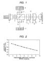
Fig. 1 is a structural view showing an optical
pickup apparatus according to a first embodiment of
the present invention. In Fig. 1, a light beam
emitted from a semiconductor laser 1 serving as a
light source is separated into a main beam and two
sub-beams by a diffractive grating 2. The sub-beams
are used to generate serve signals for DPP
(differential push-pull). The main beam is used to
record information or reproduce recorded information.
A part of the light beams having passed through
the diffractive grating 2 is reflected on a
polarizing beam splitter (PBS) 3 and condensed to a
monitor PD 5 by a condensing lens 4. An output of
the monitor PD 5 is used to control emission power of
the semiconductor laser 1.
A light beam having passed through the PBS 3
passes through a λ/4 plate 6 and is converted into a
parallel light flux by a collimator lens 13. The
parallel light flux passes through a transparent
substrate and is imaged onto an information recording
surface of an optical disk 15 by an objective lens 14.
The optical disk 15 is composed of the transparent
substrate and the information recording surface.
The collimator lens 13 includes two lens groups,
that is, a first lens group 11 composed of spherical
lenses 7 and 8 and a second lens group 12 composed of
spherical lenses 9 and 10. An interval between the
first lens group 11 and the second lens group 12 is
changeable. The interval between the first and
second lens groups is changed to correct spherical
aberration. For example, this can be realized by
driving the first lens group 11 and the second lens
group 12 relative to each other in an optical axis
direction using drive means such as a stepping motor.
A light beam reflected on the optical disk 15
passes through the objective lens 14, the collimator
lens 13, and the λ/4 plate 6 again. Then, the light
beam is reflected on the PBS 3 and condensed onto an
RF servo PD 17 by a sensor lens 16. An information
signal and the servo signals are obtained based on an
output from the RF servo PD 17.
A wavelength of the semiconductor laser 1 for
information reproduction is about 407 nm at room
temperature. The NA of the objective lens 14 is 0.85
and a focal distance thereof is 1.1765 mm.
Table 1 shows design values of a projection
system in this embodiment. Here, N(407) denotes a
refractive index at a wavelength of 407 nm, and ΔN
denotes a change in refractive index when the
wavelength is increased by 1 nm and corresponds to
dispersion in the vicinity of the wavelength of 407
nm. In addition, r denotes a lens curvature and d
denotes a surface interval.
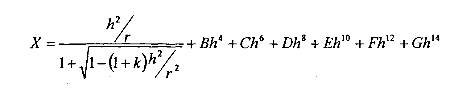
When a distance in the optical axis direction
is given by X, a height in a direction perpendicular
to the optical axis is given by h, and a conic
coefficient is given by k, an aspherical shape of the
objective lens is expressed by the following equation.
Table 2 shows aspherical coefficients k and B to G.
| | Remarks | r | D | N(407) | ΔN |
| 1 | LD | ∞ | 0.78 |
| 2 | ∞ | 0.25 | 1.52947 | -0.00008 |
| 3 | | ∞ | 1.19 |
| 4 | Diffractive grating | ∞ | 1 | 1.52947 | -0.00008 |
| 5 | ∞ | 1.6 |
| 6 | PBS | ∞ | 2.6 | 1.72840 | -0.00042 |
| 7 | λ/4 plate | ∞ | 1.15 | 1.56020 | -0.00020 |
| 8 | ∞ | 1.46 |
| 9 | | ∞ | 1.29 | 1.58345 | -0.00014 |
| 10 | -2.28 | 0.71 | 1.80480 | -0.00053 |
| 11 | Collimator lens | ∞ | 0.8 |
| 12 | 13.49 | 0.74 | 1.80480 | -0.00053 |
| 13 | 4.967 | 1.26 | 1.58345 | -0.00014 |
| 14 | -4.411 | 6.5 |
15
(Aspherical surface 1) | Objective lens | 0.89427 | 1.57 | 1.70930 | -0.00021 |
16
(Aspherical surface 2) | -3.38795 | 0.27 |
| 17 | Transparent | ∞ | 0.08 | 1.62068 | -0.00038 |
| 18 | substrate | ∞ | 0 |
| Aspherical surface coefficient. | Aspherical surface 1 | Aspherical surface 2 |
| k | -4.71569E-01 | -8.03122E+02 |
| B | 1.85624E-02 | 6.93685E-01 |
| C | -3.32437E-03 | -7.23881E-01 |
| D | 2.00843E-02 | -1.08028E+01 |
| E | -2.46799E-02 | 5.02375E+01 |
| F | 3.71610E-02 | -6.88792E+01 |
| G | -2.00730E-02 | 0 |
As is apparent from Table 1, the collimator
lens 13 is composed of only the spherical lenses and
becomes an optical element which is easily
manufactured at low cost.
Next, the case where the transparent substrate
of the optical disk 15 has a thickness error will be
described. When the transparent substrate has the
thickness error, spherical aberration is caused as
known up to now. Therefore, in the optical system
according to this embodiment, the interval between
the first lens group 11 and the second lens group 12
in the collimator lens 13 is changed to correct the
caused spherical aberration.
Fig. 2 shows a relationship between the
thickness error of the transparent substrate and a
distance between the lens groups for correcting the
thickness error. Fig. 2 shows a relationship in the
case where the first lens group 11 is moved. The
second lens group 12 is fixed. A moving distance per
µm of thickness error of the transparent substrate is
about 28 µm.
In this embodiment, when the first lens group
11 is moved. As the result, the entire length of the
optical system does not change, and therefore a
compact optical system can be constructed.
As is apparent from Fig. 1 and Table 1, the
first lens group 11 is a lens group having negative
power and the second lens group 12 is a lens group
having positive power. Therefore, the collimator
lens 13 becomes a telephoto system, a distance
between the semiconductor laser 1, and the collimator
lens 13 can be shortened to realize a compact optical
system.
Next, the case where the wavelength of the
semiconductor laser 1 changes will be described. A
problem arises in the case where focus servo control
cannot be performed in keeping with an operation
change, which corresponds to, for example, the time
immediately after operation is shifted from
reproduction to recording. When the wavelength
relatively slowly changes, defocus caused by a change
in wavelength is canceled by focus servo.
A wavelength shift when operation is shifted
from reproduction to recording is about 1 nm in the
case of a blue-violet semiconductor laser and the
wavelength generally lengthens. At this time, in the
case of the objective lens shown in Table 1, when the
wavelength is lengthened by 1 nm, the refractive
index reduces. The positive power of the objective
lens reduces to lengthen the focal distance, with the
result that defocus of 0.243 µm is caused. When NA
is 0.85 and the wavelength is 407 nm, the focal depth
is about 0.28 µm. Therefore, when the wavelength
shift is 2 nm, defocus that significantly exceeds the
focal depth takes place, so that such a case is not
suitable for recording/reproduction of information.
Thus, as shown in Table 1, with respect to the
collimator lens 13 in this embodiment, the first lens
group 11 is composed of the lens 7 having relatively
low dispersion and positive power and the lens 8
having relatively high dispersion and negative power.
The second lens group 12 is composed of the lens 9
having relatively high dispersion and negative power
and the lens 10 having relatively low dispersion and
positive power. When the wavelength lengthens, the
refractive index is changed to reduce the negative
power of the first lens group 11 and increase the
positive power of the second lens group 12.
In particular, when the lens group having the
positive power is made of a single glass material or
composed of a single lens, the positive power becomes
smaller as the wavelength lengthens. Therefore, the
defocus of the objective lens is increased to cause
larger defocus. That is, if at least power does not
change, it can be said that there is chromatic
aberration correction performance.
In this view, in this embodiment, even in the
case of the lens group having the positive power as
shown in Table 1, a glass material is used so as to
cancel the defocus of the objective lens which is
caused by an increase in wavelength. As a result,
when the wavelength lengthens, a focal distance of
the second lens group 12 becomes shorter (or does not
change) and power becomes larger. Thus, it is
possible to provide sufficient chromatic aberration
correction performance.
With respect to the lens group having the
negative power, even when it is composed of a single
lens, the negative power is reduced by a change in
refractive index. In this embodiment, the two lenses
are used such that the degree of change in power
becomes larger. Therefore, the lens group includes
the lens having high dispersion and larger negative
power.
Table 3 shows a change in focal distance, which
corresponds to a change in power of each of the lens
groups.
| | f(407) | f(408) |
| First lens group | -10.3004 | -10.3186 |
| Second lens group | 6.9678 | 6.9676 |
Here, f(407) denotes a focal distance at a wavelength
of 407 nm and f(408) denotes a focal distance at a
wavelength of 408 nm. As is apparent from Table 3, a
negative focal distance of the
first lens group 11
lengthens (that is, power becomes smaller) and a
focal distance of the
second lens group 12 slightly
shortens.
Therefore, the defocus of the objective lens
which is caused by the wavelength shift, that is, the
chromatic aberration can be sufficiently corrected.
Table 4 shows a result related to the entire
projection optical system.
| | Single objective lens | Entire system | Breakdown (extent of contribution) |
| | | | First group | Second group |
| Defocus amount | 0.243 µm | 0.141 µm | (0.091 µm) | (0.007 µm) |
As is also apparent from Table 4, the lens
group having the positive power (second lens group)
also corrects the chromatic aberration. As a result,
even when the wavelength shift is 2 nm, the defocus
amount is made smaller than the focal depth.
Therefore, even during a period in which focus servo
cannot follow the shift, the recording/reproduction
performance can be ensured.
(Second Embodiment)
Next, a second embodiment of the present
invention will be described. Table 5 shows design
values in the second embodiment, Table 6 shows change
in focal distance of each lens group, and Table 7
shows a result of chromatic aberration correction in
the entire projection optical system. An optical
system of an optical pickup apparatus according to
this embodiment has the same structure as that shown
in Fig. 1. An objective lens is also identical to
that in the first embodiment.
| | Remarks | R | D | N(407) | ΔN |
| 1 | LD | ∞ | 0.78 |
| 2 | ∞ | 0.25 | 1.52947 | -0.00008 |
| 3 | | ∞ | 1.191 |
| 4 | Diffractive grating | ∞ | 1 | 1.52947 | -0.00008 |
| 5 | ∞ | 1.605 |
| 6 | PBS | ∞ | 2.6 | 1.72840 | -0.00042 |
| 7 | λ/4 plate | ∞ | 1.15 | 1.56020 | -0.00020 |
| 8 | ∞ | 1.46 |
| 9 | Collimator lens | 28.405 | 1.3 | 1.58345 | -0.00014 |
| 10 | -2.4 | 0.7 | 1.86286 | -0.00055 |
| 11 | ∞ | 0.8 |
| 12 | 14.622 | 0.7 | 1.86286 | -0.00055 |
| 13 | 5.398 | 1.3 | 1.58345 | -0.00014. |
| 14 | -4.195 | 6.5 |
| 15 | Objective lens | 0.89427 | 1.57 | 1.70930 | -0.00021 |
| 16 | -3.38795 | 0.27 |
| 17 | Transparent substrate | ∞ | 0.08 | 1.62068 | -0.00038 |
| 18 | ∞ | 0 |
| | f (407) | f(408) |
| First lens group | -10.6477 | -10.6699 |
| Second lens group | 6.9717 | 6.9713 |
| | Single objective lens | Entire system | Breakdown (extent of contribution) |
| | | | First group | Second group |
| Defocus amount | 0.243 µm | 0.123 µm | (0.111 µm) | (0.009 µm) |
In the second embodiment, a state of the
spherical aberration correction is substantially the
same as that in the first embodiment. However, the
chromatic aberration correction in both of the first
lens group and the second lens group is further
improved.
Thus, it is possible to provide an inexpensive
and compact optical pickup apparatus that can correct
spherical aberration and chromatic aberration.