EP1603125A2 - Optical disc recording method and apparatus - Google Patents
Optical disc recording method and apparatus Download PDFInfo
- Publication number
- EP1603125A2 EP1603125A2 EP05253342A EP05253342A EP1603125A2 EP 1603125 A2 EP1603125 A2 EP 1603125A2 EP 05253342 A EP05253342 A EP 05253342A EP 05253342 A EP05253342 A EP 05253342A EP 1603125 A2 EP1603125 A2 EP 1603125A2
- Authority
- EP
- European Patent Office
- Prior art keywords
- optical disc
- equal
- recording
- width
- user data
- Prior art date
- Legal status (The legal status is an assumption and is not a legal conclusion. Google has not performed a legal analysis and makes no representation as to the accuracy of the status listed.)
- Granted
Links
Images


Classifications
-
- G—PHYSICS
- G11—INFORMATION STORAGE
- G11B—INFORMATION STORAGE BASED ON RELATIVE MOVEMENT BETWEEN RECORD CARRIER AND TRANSDUCER
- G11B7/00—Recording or reproducing by optical means, e.g. recording using a thermal beam of optical radiation by modifying optical properties or the physical structure, reproducing using an optical beam at lower power by sensing optical properties; Record carriers therefor
- G11B7/007—Arrangement of the information on the record carrier, e.g. form of tracks, actual track shape, e.g. wobbled, or cross-section, e.g. v-shaped; Sequential information structures, e.g. sectoring or header formats within a track
-
- G—PHYSICS
- G11—INFORMATION STORAGE
- G11B—INFORMATION STORAGE BASED ON RELATIVE MOVEMENT BETWEEN RECORD CARRIER AND TRANSDUCER
- G11B7/00—Recording or reproducing by optical means, e.g. recording using a thermal beam of optical radiation by modifying optical properties or the physical structure, reproducing using an optical beam at lower power by sensing optical properties; Record carriers therefor
- G11B7/24—Record carriers characterised by shape, structure or physical properties, or by the selection of the material
- G11B7/2407—Tracks or pits; Shape, structure or physical properties thereof
- G11B7/24073—Tracks
- G11B7/24079—Width or depth
-
- G—PHYSICS
- G11—INFORMATION STORAGE
- G11B—INFORMATION STORAGE BASED ON RELATIVE MOVEMENT BETWEEN RECORD CARRIER AND TRANSDUCER
- G11B7/00—Recording or reproducing by optical means, e.g. recording using a thermal beam of optical radiation by modifying optical properties or the physical structure, reproducing using an optical beam at lower power by sensing optical properties; Record carriers therefor
- G11B7/004—Recording, reproducing or erasing methods; Read, write or erase circuits therefor
- G11B7/0045—Recording
-
- G—PHYSICS
- G11—INFORMATION STORAGE
- G11B—INFORMATION STORAGE BASED ON RELATIVE MOVEMENT BETWEEN RECORD CARRIER AND TRANSDUCER
- G11B7/00—Recording or reproducing by optical means, e.g. recording using a thermal beam of optical radiation by modifying optical properties or the physical structure, reproducing using an optical beam at lower power by sensing optical properties; Record carriers therefor
- G11B7/007—Arrangement of the information on the record carrier, e.g. form of tracks, actual track shape, e.g. wobbled, or cross-section, e.g. v-shaped; Sequential information structures, e.g. sectoring or header formats within a track
- G11B7/00736—Auxiliary data, e.g. lead-in, lead-out, Power Calibration Area [PCA], Burst Cutting Area [BCA], control information
-
- G—PHYSICS
- G11—INFORMATION STORAGE
- G11B—INFORMATION STORAGE BASED ON RELATIVE MOVEMENT BETWEEN RECORD CARRIER AND TRANSDUCER
- G11B7/00—Recording or reproducing by optical means, e.g. recording using a thermal beam of optical radiation by modifying optical properties or the physical structure, reproducing using an optical beam at lower power by sensing optical properties; Record carriers therefor
- G11B7/24—Record carriers characterised by shape, structure or physical properties, or by the selection of the material
Definitions
- the present invention relates to an optical disc recording method and an optical disc recording apparatus in which data is recorded on a recordable optical disc.
- Recordable optical discs such as a CD-R, a CD+R, a DVD-R, a DVD+R, a DVD-RAM, a DVD-RW, a DVD+RW, or the like have been put to wide use in recent years. These optical discs have a guide slot known as a groove which is previously formed thereon to enable accurate tracking even in unrecorded conditions. In addition, address information is previously embedded using groove wobbling, land pre-pit, or the like to thereby enable data writing at a desired position.
- a play-only apparatus is generally capable of tracing only a pit train, the tracing of tracks is not performed in an unrecorded region including no pit train. Further, it is also impossible to recognize the address information embedded by groove wobbling or the like, which results in inability to identify an address in the unrecorded region. Therefore, to enable reproduction by the play-only apparatus, i.e. to ensure playability of such a play-only apparatus, an optical disc needs a recorded region having a certain width.
- a guard zone is provided to an outer radius side of a user data area where user date is recorded, to protect an optical pickup from overrunning.
- an inner radius side of the user data area is allocated to a control data area for reproduction where information necessary for reproduction of the user data area is recorded.
- Fig. 7 shows a data layout in a DVD-R.
- a control data area A0' to be used during data recording is formed on the innermost circumference.
- An outer radius side of the control data area A0' is allocated to an inner guard zone A1' to prevent overrun or the like.
- Each unit of one recording operation including a control data area for reproduction A2' and an outer guard zone A4' with a user data area A3' sandwiched therebetween is sequentially recorded on an outer radius side of the inner guard zone A1'.
- the width of the control data area for reproduction A2' is approximately 240 ⁇ m (equivalent to approximately 324 tracks), the width of the outer guard zone A4' is approximately 500 ⁇ m (equivalent to approximately 676 tracks), and the width of the user data area A3' is greater than or equal to approximately 1650 ⁇ m (equivalent to approximately 2230 tracks, which is the minimum recording width).
- control data area for reproduction and the outer guard zone or the padding data for filling the minimum recording width consume a recordable region of an optical disc in addition to causing an increase in length of data writing time. More specifically, even when an amount of user data equivalent to one track data is recorded, approximately 3230 tracks are used in a DVD-R while taking the length of time required for writing approximately 3230 tracks of data.
- the present invention provides an optical disc recording method in which data is recorded on an optical disc using a combination of a user data area where user data is recorded, a control data area for reproduction allocated on an inner radius side of the user data area, and an outer guard zone allocated on an outer radius side of the user data area as a unit of one recording operation.
- a track pitch TP of the optical disc is greater than or equal to 0.3 ⁇ m and smaller than or equal to 0.4 ⁇ m
- the width of the outer guard zone along a radius direction of the optical disc is greater than or equal to a value of (100 ⁇ TP) and smaller than or equal to a value of (125 ⁇ TP).
- the present invention provides an optical disc recording apparatus in which data is recorded on an optical disc using a combination of a user data area where user data is recorded, a control data area for reproduction allocated on an inner radius side of the user data area, and an outer guard zone allocated on an outer radius side of the user data area as a unit of one recording operation.
- a track pitch TP of the optical disc is greater than or equal to 0.3 ⁇ m and smaller than or equal to 0.4 ⁇ m
- the width of the outer guard zone along a radius direction of the optical disc is greater than or equal to a value of (100 ⁇ TP) and smaller than or equal to a value of (125 ⁇ TP).
- Fig. 1 is a sectional view showing a layer structure of an optical disc D according to the present embodiment.
- Fig. 2 is a perspective view showing an enlarged surface of a recording layer Db of the optical disc D according to the embodiment.
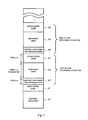
- Fig. 3 shows a data layout of the optical disc D according to the embodiment.
- Fig. 4 is a block diagram depicting a structure of an optical disc recording and reproducing apparatus 100 according to the embodiment.
- the optical disc recording and reproducing apparatus 100 performs recording and reproducing operations not in the format standardized for DVD-Rs or the like but in a new format defined below.
- the optical disc D and the optical disc recording and reproducing apparatus 100 have a lot of commonalities with conventional discs, such as a DVD-R, or the like, and conventional optical disc recording and reproducing apparatuses. Then, following a brief description about basic structures of the optical disc D and the optical disc recording and reproducing apparatus 100, specific features of this embodiment will be described.
- the optical disc D according to this embodiment is described with reference to Figs. 1 and 2.
- the optical disc D comprises, as shown in Fig. 1, a recording layer Db and a protective layer (also referred to as a cover layer) Dc laminated on a disc substrate Da having the geometry of a circular plate (which is 120 mm in diameter and 1.2 mm in thickness in this embodiment).
- the optical disc D is preferably of a write-once read-multiple type, but may be of a rewritable type.
- the recording layer Db of the optical disc D has grooves G being guide slots formed in a concentric or spiral fashion along a direction of the circumference of the optical disc D and lands L formed between the grooves G.
- data is recorded on the grooves G.
- the grooves G wobble as shown in Fig. 2, and by means of such wobbling, data writing on an unrecorded region of the optical disc D is enabled. More specifically, data such as address information, rotational speed information, or the like can be retrieved using a wobble signal obtained by the wobbling.
- the address information may be embedded in another form such as a land pre-pit (LPP) or the like.
- a track pitch Spacing between recording tracks along a radius direction of the optical disc D is referred to as a track pitch. As shown in Fig. 2, spacing between adjacent groove tracks is a track pitch TP in this embodiment.
- a data layout of the optical disc D in this embodiment will be described with reference to Fig. 3.
- a control data area A0 which is used during a recording operation. More specifically, user data control information which is used during a recording operation is recorded on the control data area A0.
- a further inner radius side of the control data area A0 may be allocated to a test area where trial writing is performed.
- the outer radius side of the control data area A0 is a recordable area where one or more user data areas A3 are sequentially formed.
- the user data areas A3 store user data written therein.
- a combination of the control data area for reproduction A2, the user data area A3, and the outer guard zone A4 is regarded as a unit of one recording operation.
- an inner guard zone A1 is formed on an inner radius side of the unit of one recording operation recorded on the innermost track, i.e. on the inner radius side of the innermost control data area for reproduction A2, an inner guard zone A1 is formed.
- guard zones A1 and A4 are guard bands including padding data or the like. These guard zones A1 and A4 are buffering regions to protect an optical pickup from overrunning as well as being regions which work to facilitate smooth reading at a leading edge of the control data area for reproduction A2 formed immediately outside the guard zone A1 or A4.
- Data is recorded on the optical disc D sequentially in the user data area A3, the control data area for reproduction A2, the control data area A0, and the outer guard zone A4 in that order, for example.
- the process of disabling writing to the optical disc D is performed, for example, such that write disable information is entered in the outer guard zone A4 when writing is disabled as well as recording of user data, whereas an outer guard zone A4 including write disable information is formed on the outermost circumference when writing is disabled independently of the recording of user data.
- the optical disc D is placed on a turntable 1 which is driven for rotation by a spindle motor 2.
- the spindle motor 2 is driven by a spindle driver 3.
- An optical pickup 20 is placed below the under surface of the optical disc D.
- Data writing and data reading to/from the optical disc D is performed by applying a laser beam from the optical pickup 20 to the optical disc D. More specifically, by irradiating a recording layer Db with a recording laser beam modulated in accordance with data to be recorded (hereinafter referred to as "recording data"), a pit train corresponding to the recording data is formed on the recording layer Db. Then, when the pit train is irradiated with a reproducing laser beam, changes in reflectance of the laser beam is detected, to thereby read data having been written on the optical disc D.
- recording data a recording laser beam modulated in accordance with data to be recorded
- the optical pickup 20 has an object lens 21, a laser diode 22 which emits a laser beam applied through the object lens 21 to the optical disc D, and a photodetector 23 which receives light reflected from the optical disc D, embedded therein.
- the laser diode 22 is driven by a laser driver 4.
- a beam spot S is formed on the recording layer Db of the optical disc D by irradiation with the laser beam from the optical pickup 20.
- the object lens 21 can be moved along a radius direction of the optical disc D by a tracking actuator 24 driven by a tracking driver 5.
- the tracking actuator 24 moves the object lens 21 specifically when relatively small movement of the beam spot S on a disc surface, such as relatively small jump (a fine seek), relatively small tracking, or the like is needed.
- a moving range of the object lens 21 operated by the tracking actuator 24 is, for example, approximately ⁇ 200 ⁇ m.
- the entire optical pickup unit 20 is movable along the radius direction of the optical disc D by means of a thread motor 6 driven by a thread driver 7.
- the thread motor 6 moves the entire optical pickup 20 when relatively large movement of the beam spot S on the disc surface, such as relatively large track jump (a rough seek) or the like, is needed.
- a signal detected by the photodetector 23 in the optical pickup 20 is supplied to an RF signal processing circuit 8.
- the RF signal processing circuit 8 generates a focus error signal, a tracking error signal, a tilt error signal, and a wobble signal based on the signal supplied from the photodetector 23.
- a reproduction signal corresponding to the pit train formed on the recording layer Db is further generated.
- the focus error signal, the tracking error signal, the tilt error signal generated by the RF signal processing circuit 8 are fed to a focus control circuit 9, a tracking control circuit 10, and a tilt control circuit 11, respectively.
- the focus control circuit 9 controls a focus actuator (not illustrated) through a focus driver 12 based on the focus error signal
- the tracking control circuit 10 controls a tacking actuator 24 through the tracking driver 5 based on the tracking error signal
- the tilt control circuit 11 controls a tilt actuator (not illustrated) through a tilt driver 13 based on the tilt error signal.
- a focus servo loop for maintaining laser light in a state focused on the recording layer Db of the optical disc D
- a tracking servo loop for causing the beam spot S to follow a track
- a tilt servo loop for holding the optical axis of laser light in a position perpendicular to the disc surface.
- the wobble signal generated by the RF signal processing circuit 8 is supplied to a system control circuit 14 in which identification of an address is enabled by the wobble signal.
- the system control circuit 14 is a CPU or the like which controls the overall optical disc recording and reproducing apparatus 100 according to a command signal from a host device 18.
- a reproduction signal produced in the RF signal processing circuit 8 is supplied to a digital signal processing circuit 15 in which the reproduction signal supplied is processed through predetermined signal conditioning (for example, demodulation and error correction) to produce reproduction data and control data.
- the reproduction data produced by the digital signal processing circuit 15 is temporarily stored in a memory 16, such as a RAM, and then output via an interface 17 to the host device 18, such as a computer or the like.
- the control data produced by the digital signal processing circuit 15 is supplied to the system control circuit 14.
- the digital signal processing circuit 15 Upon receipt of recording data from the host device 18 during recording, the digital signal processing circuit 15 temporarily stores the recording data in the memory 16 to process the recording data through predetermined conditioning (for example, modulation and error-correction coding) for generation of a write signal.
- the write signal is supplied to the laser driver 4 which actuates the laser diode 22 according to the write signal. Through the actuation of the laser diode 22, a pit train corresponding to the recording data is formed on the recording layer Db, with a result that the recording data is recorded on the optical disc D.
- a pickup advance mechanism a mechanism to move the entire optical pickup 20 (hereinafter referred to as a pickup advance mechanism) will be described with reference to Fig. 5 in which a structure of the pickup advance mechanism is depicted as an example.
- the optical pickup 20 is movably supported by a guide shaft 31 and provided with a rack 32 mounted, on a side of the optical pickup 20 (on the left side in the figure), in parallel with the guide shaft 31.
- Driving torque of the thread motor 6 (a brush motor in this example) is transmitted from a drive gear 33 attached to the thread motor 6 via a reduction gear 34 engaging with the drive gear 33 to a pinion 35 which is coaxially integrated with the reduction gear 34.
- the drive torque transmitted as described above is converted into a thrust force generating rectilinear motion through the engagement of the pinion 35 and the rack 32.
- the optical pickup 20 is displaced along the guide shaft 31 by the thrust force.
- a travel stroke (a unit amount of traveling) of the optical pickup 20 can be shortened, which facilitates smooth movement of the optical pickup 20, yet reduces the speed of travel of the optical pickup 20.
- the speed of travel can be increased, whereas the travel stroke is lengthened, thereby expanding torque load of the thread motor 6.
- the travel stroke be set to approximately 80 ⁇ m. With this stroke, the accuracy with which the pickup advance mechanism moves the beam spot S, i.e. allowable differences between an actual travel distance and a target travel distance of the beam spot S, will be approximately ⁇ 40 ⁇ m.
- the laser diode 22 shown in Fig. 4 is a blue laser diode emitting a blue laser light with wavelengths of 400-410 nm.
- spot size the diameter of the beam spot S (hereinafter referred to as "spot size") formed on the recording layer Db can be minimized.
- a typical spot size formed on DVD-Rs is approximately 0.9 ⁇ m, whereas the spot size is set to approximately 0.6 ⁇ m in this embodiment.
- Such a reduced spot size contributes to decrease of the track pitch TP.
- the track pitch TP of a DVD-R is typically approximately 0.74 ⁇ m, whereas the track pitch TP of this embodiment is established within a range of from 0.3 to 0.4 ⁇ m.
- width denotes a width along the radius direction of the optical disc D.
- the control data area for reproduction A2 must contain approximately 50 to 125 tracks to record user data control information. Therefore, in this embodiment, the number of tracks in the control data area for reproduction A2 is specified within a range of from 50 to 125.
- the width of the control data area for reproduction A2 along the radius direction of the optical disc D is defined within a range of from a value of TP multiplied by 50 to a value of TP multiplied by 125. Accordingly, the width of the control data area for reproduction A2 takes on values from 15 ⁇ m to 50 ⁇ m.
- the width of the control data area for reproduction A2 may preferably be defined within a range of from a value of (50 ⁇ TP) to a value of (150 ⁇ TP).
- the inner guard zone A1 and the outer guard zone A4 be configured to contain approximately 100 to 125 tracks, which is preferable also in terms of facilitating smooth reading at each leading edge of the control data areas for reproduction A2 formed outside the zones A1 and A4.
- the accuracy with which the optical pickup 20 remains within the zone in a seeking operation represents that the above-described number of tracks will prevent, with a 99.9% or greater probability, the optical pickup 20 from entering into an unrecorded area.
- the number of tracks constituting the inner guard zone A1 and the outer guard zone A4 is specified within a range of values from 100 to 125.
- the width of the inner and outer guard zones A1 and A4 along the radius direction of the optical disc D is defined within a range of from a value of (100 ⁇ TP) to a value of (125 ⁇ TP). Accordingly, the width of the inner and outer guard zones A1 and A4 takes on values of 30-50 ⁇ m. It is preferable in terms of securing overrun protection that the width of the inner or outer guard zone A1 or A4 be specified within a range of from a value of (100 ⁇ TP) to a value of (150 ⁇ TP).
- the width of the user data area A3 is determined based on the precision of a track jump position in the reproduction system, i.e. determined based on allowable difference between an actually accessed position and a target access position after track jump. To facilitate access to a desired track, the user data area A3 must have a width covering al least a dimension corresponding to the precision of track jump position. Further, in consideration of an error of the track pitch TP and backlash of the gears, a width approximately 2 to 2.5 times as wide as the above-described width is needed for ensuring stability of track access.
- the precision of track jump position can be expressed as ⁇ (A + B + C), where ⁇ A is the accuracy with which the pickup advance mechanism moves the beam spot S, B is the amount of decentering of the disc, and C is an error of chucking of the optical disc D.
- the width of the user data area A3 is set, regardless of the amount of user data to be recorded, to a width equal to or greater than the minimum recording width which is specified within a range of values from ⁇ (A + B + C) ⁇ 2 ⁇ to ⁇ (A + B + C) ⁇ 2 ⁇ 2.5 ⁇ .
- the widths of the control data area for reproduction A2 and the inner and outer guard zones A1 and A4, and the minimum recording width of the user data area A3 are also defined according to the above-described definition scheme, for example, as indicated in the following example of setting values.
- the track pitch TP is set to 0.4 ⁇ m
- the number of tracks constituting the control data area for reproduction A2 and the inner and outer guard zones A1 and A4 is set to 125.
- the control data area for reproduction A2 and the inner and outer guard zones A1 and A4 have the width of 50 ⁇ m.
- the minimum recording width is set to 1000 ⁇ m.
- Fig. 3 shows numeric values indicated in the above-described example of setting values.
- the width of the user data area A3 is equal to the minimum recording width.
- Fig. 6 shows the relationship between the size (diameter) of the foreign material and the incidence of tracking failure.
- the solid line depicts the relationship in a case where the diameter of the reproduction beam spot Sc is 1 mm
- the broken line depicts a case where the diameter of the reproduction beam spot Sc is 0.3 mm.
- the diameter of the foreign material when the diameter of the foreign material is equal to or smaller than the diameter of the reproduction beam spot Sc, the foreign material causes almost no tracking failure.
- the incidence of tracking failure sharply increases as the diameter of the foreign material grows beyond the diameter of the reproduction beam spot Sc.
- a cartridge to house the optical disc D is unnecessary as long as data can be reproduced in the event of the occurrence of a foreign material having a diameter of approximately 1 mm adhering to the optical disc D, the necessity of using the cartridge arises when data cannot be reproduced in the above-described event.
- the diameter of the reproduction beam spot Sc at the surface of the protective layer Dc is set to approximately 1 mm in this embodiment. It should be noted that the thickness of the protective layer Dc shown in Fig. 1 is approximately 0.6 mm.
- the width of the outer guard zone A4 is defined to be smaller than or equal to the value of (125 ⁇ TP) in the above-described embodiment, the width of the outer guard zone A4 according to the embodiment becomes narrower than that of typical DVD-R or the like.
- the width of the outer guard zone A4 in a conventional DVD-R is 500 ⁇ m, while the width according to this embodiment is 50 ⁇ m or smaller.
- a proportion of the outer guard zone A4 in the total recordable area of the optical disc D can be minimized according to this embodiment, thereby enabling reduction in proportion of data, such as padding data or the like, which is regarded as useless data by users.
- user data can be recorded on the optical disc D with a higher degree of efficiency, which brings about an improvement in spatial and temporal efficiencies of recording.
- the width of the outer guard zone A4 is determined to be greater than or equal to the value of (100 ⁇ TP), the number of tracks required for preventing overrun or the like can be secured, to thereby ensure playability of the play-only apparatus.
- the track pitch TP of the optical disc D is defined within the range of from 0.3 ⁇ m to 0.4 ⁇ m, and the width of the control data area for reproduction A2 is defined to be smaller than or equal to a value of (125 ⁇ TP), the width of the control data area for reproduction A2 becomes narrower compared with conventional DVD-R or the like.
- the width of the control data area for reproduction A2 in a conventional DVD-R is 240 ⁇ m, while the width in this embodiment is 50 ⁇ m or smaller.
- the width of the control data area for reproduction A2 is determined to be greater than or equal to a value of (50 ⁇ TP), the number of tracks required for recording user data control information can be secured, to thereby ensure playability of the play-only apparatus.
- the track pitch TP of the optical disc D is defined within the range of from 0.3 ⁇ m to 0.4 ⁇ m
- the width of the inner guard zone A1 is defined within the range of from a value of (100 ⁇ TP) to a value of (125 ⁇ TP), similarly to the outer guard zone A4, the spatial or temporal efficiency of recording can be improved while ensuring playability of the play-only apparatus.
- the minimum recording width of the user data area A3 is set to 1050 ⁇ m or smaller, the minimum recording width becomes narrower compared with a typical DVD-R having the minimum recording width of 1650 ⁇ m.
- a proportion of the minimum recording width in the total recordable area of the optical disc D can be minimized according to this embodiment, thereby enabling reduction in proportion of data, such as padding data or the like, regarded as useless data by users.
- user data can be recorded on the optical disc D with a higher degree of efficiency, which brings about an improvement in spatial and temporal efficiencies of recording.
- the minimum recording width is set to 420 ⁇ m or greater, the recording width necessary for smooth access to the tracks in a play-only apparatus can be secured, to thereby preferably ensure playability of the play-only apparatus.
- the diameter of the reproduction beam spot Sc at the surface of the protective layer Dc is set to approximately 1 mm, reproduction can be performed even in the event of the occurrence of foreign material having a diameter of 1 mm adhering to the optical disc D. In this manner, it becomes unnecessary to use the cartridge to house the optical disc D.
- optical disc recording and reproducing apparatus 100 may be changed as appropriate.
- recording and reproducing of data may be performed by a physically separate recording apparatus and a reproduction apparatus.
- the width of the outer guard zone is greater than or equal to a value of (100 ⁇ TP) and smaller than or equal to a value of (125 ⁇ TP);
- the width of the control data area for reproduction is greater than or equal to a value of (50 ⁇ TP) and smaller than or equal to a value of (125 ⁇ TP);
- the width of the inner guard zone is greater than or equal to a value of (100 ⁇ TP) and smaller than or equal to a value of (125 ⁇ TP);
- the minimum recording width in the user data area is greater than or equal to 420 ⁇ m and smaller than or equal to 1050 ⁇ m; and
- the diameter of the reproduction beam spot at the surface of the protective layer is approximately 1mm, be satisfied, it is also preferable that one to four conditions appropriately selected from the above conditions be satisfied.
Landscapes
- Optical Recording Or Reproduction (AREA)
- Optical Record Carriers And Manufacture Thereof (AREA)
- Optical Head (AREA)
Abstract
Description
Claims (14)
- An optical disc recording method in which data is recorded on an optical disc using a combination of a user data area where user data is recorded, a control data area for reproduction allocated on an inner radius side of said user data area, and an outer guard zone allocated on an outer radius side of said user data area as a unit of one recording operation, wherein:a track pitch TP of said optical disc is greater than or equal to 0.3 µm and smaller than or equal to 0.4 µm, andthe width of said outer guard zone along a radius direction of said optical disc is greater than or equal to a value of (100 × TP) and smaller than or equal to a value of (125 × TP).
- The optical disc recording method according to Claim 1, wherein:the width of said control data area for reproduction along the radius direction of said optical disc is greater than or equal to a value of (50 × TP) and smaller than or equal to a value of (125 × TP).
- The optical disc recording method according to Claim 1, wherein:an inner guard zone is formed on an inner radius side of the unit of one recording operation recorded on an innermost circumference, andthe width of said inner guard zone along the radius direction of said optical disc is greater than or equal to a value of (100 × TP) and smaller than or equal to a value of (125 × TP).
- The optical disc recording method according to Claim 1, wherein:the width of said user data area along the radius direction of said optical disc is determined to be greater than or equal to a predetermined minimum recording width regardless of the amount of user data to be recorded, andsaid minimum recording width is greater than or equal to 420 µm and smaller than or equal to 1050 µm.
- The optical disc recording method according to Claim 2, wherein:said minimum recording width is greater than or equal to 420 µm and smaller than or equal to 1050 µm.an inner guard zone is formed on an inner radius side of the unit of one recording operation recorded on an innermost circumference, andthe width of said inner guard zone along the radius direction of said optical disc is greater than or equal to a value of (100 × TP) and smaller than or equal to a value of (125 × TP);the width of said user data area along the radius direction of said optical disc is determined to be greater than or equal to a predetermined minimum recording width regardless of the amount of user data to be recorded, and
- An optical disc recording and reproducing method including the optical disc recording method according to Claim 1 wherein:said optical disc has a protective layer laminated on a surface of a recording layer where data is recorded, anda diameter of a reproduction beam spot at a surface of said protective layer is approximately 1 mm.
- An optical disc recording and reproducing method including the optical disc recording method according to Claim 5, wherein:said optical disc has a protective layer laminated on a surface of a recording layer where data is recorded, anda diameter of a reproduction beam spot at a surface of said protective layer is approximately 1 mm.
- An optical disc recording apparatus in which data is recorded on an optical disc using a combination of a user data area where user data is recorded, a control data area for reproduction allocated on an inner radius side of said user data area, and an outer guard zone allocated on an outer radius side of said user data area as a unit of one recording operation, wherein:a track pitch TP of said optical disc is greater than or equal to 0.3 µm and smaller than or equal to 0.4 µm, andthe width of said outer guard zone along a radius direction of said optical disc is greater than or equal to a value of (100 × TP) and smaller than or equal to a value of (125 × TP).
- The optical disc recording apparatus according to Claim 8, wherein:the width of said control data area for reproduction along the radius direction of said optical disc is greater than or equal to a value of (50 × TP) and smaller than or equal to a value of (125 × TP).
- The optical disc recording apparatus according to Claim 8, wherein:an inner guard zone is formed on an inner radius side of the unit of one recording operation recorded on an innermost circumference, andthe width of said inner guard zone along the radius direction of said optical disc is greater than or equal to a value of (100 × TP) and smaller than or equal to a value of (125 × TP).
- The optical disc recording apparatus according to Claim 8, wherein:said minimum recording width is greater than or equal to 420 µm and smaller than or equal to 1050 µm.the width of said user data area along the radius direction of said optical disc is determined to be greater than or equal to a predetermined minimum recording width regardless of the amount of user data to be recorded, and
- The optical disc recording apparatus according to Claim 9, wherein:said minimum recording width is greater than or equal to 420 µm and smaller than or equal to 1050 µm.an inner guard zone is formed on an inner radius side of the unit of one recording operation recorded on an innermost circumference, andthe width of said inner guard zone along the radius direction of said optical disc is greater than or equal to a value of (100 × TP) and smaller than or equal to a value of (125 × TP);the width of said user data area along the radius direction of said optical disc is determined to be greater than or equal to a predetermined minimum recording width regardless of the amount of user data to be recorded, and
- An optical disc recording and reproducing apparatus including the optical disc recording apparatus according to Claim 8, wherein:said optical disc has a protective layer laminated on a surface of a recording layer where data is recorded, anda diameter of a reproduction beam spot at a surface of said protective layer is approximately 1 mm.
- An optical disc recording and reproducing apparatus including the optical disc recording apparatus according to Claim 12, wherein:said optical disc has a protective layer laminated on a surface of a recording layer where data is recorded, anda diameter of a reproduction beam spot at a surface of said protective layer is approximately 1 mm.
Applications Claiming Priority (2)
| Application Number | Priority Date | Filing Date | Title |
|---|---|---|---|
| JP2004164625 | 2004-06-02 | ||
| JP2004164625A JP4201740B2 (en) | 2004-06-02 | 2004-06-02 | Optical disc recording method and optical disc recording apparatus |
Publications (3)
| Publication Number | Publication Date |
|---|---|
| EP1603125A2 true EP1603125A2 (en) | 2005-12-07 |
| EP1603125A3 EP1603125A3 (en) | 2006-11-29 |
| EP1603125B1 EP1603125B1 (en) | 2008-05-28 |
Family
ID=34941521
Family Applications (1)
| Application Number | Title | Priority Date | Filing Date |
|---|---|---|---|
| EP05253342A Expired - Lifetime EP1603125B1 (en) | 2004-06-02 | 2005-05-31 | Optical disc recording method and apparatus |
Country Status (7)
| Country | Link |
|---|---|
| US (1) | US7492697B2 (en) |
| EP (1) | EP1603125B1 (en) |
| JP (1) | JP4201740B2 (en) |
| KR (1) | KR100697802B1 (en) |
| CN (1) | CN1324575C (en) |
| DE (1) | DE602005007106D1 (en) |
| TW (1) | TWI327723B (en) |
Families Citing this family (2)
| Publication number | Priority date | Publication date | Assignee | Title |
|---|---|---|---|---|
| JP2007234204A (en) * | 2006-01-31 | 2007-09-13 | Toshiba Corp | Information storage medium, information recording method, and information recording apparatus |
| CN112292725B (en) * | 2018-06-20 | 2022-11-01 | 索尼公司 | Information recording device, information reproducing device, information recording medium, method, and program |
Family Cites Families (22)
| Publication number | Priority date | Publication date | Assignee | Title |
|---|---|---|---|---|
| US5031168A (en) * | 1986-02-05 | 1991-07-09 | Information Storage, Inc. | Apparatus and method for increasing storage capacity of recording media |
| JP2638248B2 (en) * | 1990-03-15 | 1997-08-06 | 松下電器産業株式会社 | Optical information medium, reproducing apparatus, recording apparatus, reproducing method and recording method |
| EP0793221B1 (en) * | 1990-05-25 | 2006-08-02 | Hitachi, Ltd. | Optical recording method and apparatus |
| JP3787925B2 (en) | 1996-11-14 | 2006-06-21 | ソニー株式会社 | Objective lens device and recording / reproducing device |
| KR100459161B1 (en) * | 1998-11-20 | 2005-01-15 | 엘지전자 주식회사 | optical recording medium and method for assigning spare area and for managing defect area of optical recording medium |
| MY130565A (en) | 1998-09-18 | 2007-06-29 | Samsung Electronics Co Ltd | Near-field optical storage medium and optical data storage system therefor |
| US6535477B1 (en) * | 1999-06-28 | 2003-03-18 | Pioneer Corporation | Optical recording medium having groove and land tracks, and method of manufacturing the same |
| EP1152402B1 (en) * | 1999-07-15 | 2006-11-15 | Matsushita Electric Industrial Co., Ltd. | Optical recording medium and method for recording optical recording medium |
| JP2001266495A (en) | 2000-03-24 | 2001-09-28 | Sony Corp | Optical disk and optical disk drive |
| JP3786343B2 (en) | 2000-05-12 | 2006-06-14 | 日本ビクター株式会社 | Optical disk playback device |
| KR100796327B1 (en) * | 2000-11-20 | 2008-01-21 | 소니 가부시끼 가이샤 | Optical record carrier and optical disc device |
| JP3708483B2 (en) | 2000-12-26 | 2005-10-19 | パイオニア株式会社 | Information recording medium, information recording apparatus, and information recording method |
| JP2002203340A (en) | 2000-12-28 | 2002-07-19 | Tdk Corp | Optical information media |
| KR20020074996A (en) * | 2001-03-23 | 2002-10-04 | 엘지전자 주식회사 | Interchangeable high density optical disc and optical disc apparatus |
| JP2003036543A (en) * | 2001-07-24 | 2003-02-07 | Pioneer Electronic Corp | Recording disk and device for reproducing recorded information |
| JP3438729B2 (en) | 2001-09-10 | 2003-08-18 | ソニー株式会社 | Playback device control method |
| KR20030030506A (en) * | 2001-10-11 | 2003-04-18 | 삼성전자주식회사 | High density optical disc |
| US20030142560A1 (en) * | 2001-12-07 | 2003-07-31 | Pioneer Corporation | Data recording medium, reproduction apparatus, recording apparatus, reproducing method, recording method, computer-readable recorded medium in which reproducing program is recorded, and computer-readable recorded medium in which recording program is recorded |
| US6999390B2 (en) | 2002-05-06 | 2006-02-14 | Samsung Electronics Co., Ltd. | Optical disk and method of recording data in the same |
| JP2003338138A (en) * | 2002-05-22 | 2003-11-28 | Pioneer Electronic Corp | Information recording medium, method and device for recording the same, and reproducing device for the same |
| JP2004046997A (en) | 2002-07-15 | 2004-02-12 | Nikon Corp | Optical disk and stamper |
| JP3916546B2 (en) * | 2002-10-24 | 2007-05-16 | パイオニア株式会社 | Playback-only recording medium |
-
2004
- 2004-06-02 JP JP2004164625A patent/JP4201740B2/en not_active Expired - Fee Related
-
2005
- 2005-05-26 KR KR1020050044654A patent/KR100697802B1/en not_active Expired - Fee Related
- 2005-05-31 DE DE602005007106T patent/DE602005007106D1/en not_active Expired - Lifetime
- 2005-05-31 EP EP05253342A patent/EP1603125B1/en not_active Expired - Lifetime
- 2005-06-01 US US11/141,833 patent/US7492697B2/en not_active Expired - Fee Related
- 2005-06-02 TW TW094118115A patent/TWI327723B/en not_active IP Right Cessation
- 2005-06-02 CN CNB2005100735494A patent/CN1324575C/en not_active Expired - Fee Related
Also Published As
| Publication number | Publication date |
|---|---|
| KR20060046204A (en) | 2006-05-17 |
| EP1603125A3 (en) | 2006-11-29 |
| DE602005007106D1 (en) | 2008-07-10 |
| TWI327723B (en) | 2010-07-21 |
| JP4201740B2 (en) | 2008-12-24 |
| US20050270966A1 (en) | 2005-12-08 |
| EP1603125B1 (en) | 2008-05-28 |
| KR100697802B1 (en) | 2007-03-20 |
| JP2005346818A (en) | 2005-12-15 |
| TW200606877A (en) | 2006-02-16 |
| CN1324575C (en) | 2007-07-04 |
| CN1707633A (en) | 2005-12-14 |
| US7492697B2 (en) | 2009-02-17 |
Similar Documents
| Publication | Publication Date | Title |
|---|---|---|
| US7489620B2 (en) | Optical information recording and reproducing medium | |
| US6069868A (en) | Multiple layer optical disk storing information at a like multiple densities | |
| US7787334B2 (en) | Optical recording method on multilayer optical recording medium, optical recording apparatus, and multilayer optical recording medium | |
| US20070253307A1 (en) | Optical disk drive and method for recording data | |
| US7929390B2 (en) | Optical recording method on multilayer optical recording medium and optical recording apparatus | |
| WO2003046902A1 (en) | Multilayer optical recording medium, method for recording data, and recorder | |
| US6970409B2 (en) | Information recording apparatus | |
| US7492697B2 (en) | Optical disc recording method and apparatus | |
| JP4838126B2 (en) | Optical disk device | |
| JP2007048404A (en) | Information recording medium, information processing apparatus and method, and processing controlling computer program for executing recording or reproduction | |
| US20050147001A1 (en) | Method or recording information, computer program, computer readable storage medium, and optical disk apparatus that stably record information on optical disk with high recording quality | |
| JP3522937B2 (en) | Optical disk signal recording / reproducing method | |
| JP2005056543A (en) | Dual-layer disc discrimination method and optical disc apparatus | |
| JP3522938B2 (en) | Optical disk signal recording / reproducing method | |
| US7848215B2 (en) | Optical recording medium, information recording apparatus and information reproduction apparatus | |
| JPH08124158A (en) | Optical disk data erasing device | |
| JP4335832B2 (en) | Optical recording medium, information recording apparatus, and information reproducing apparatus | |
| JP5034051B2 (en) | Optical recording medium | |
| JP4321439B2 (en) | Optical disk device | |
| WO2006025287A1 (en) | Information recording device and computer program | |
| JP2006040377A (en) | Optical disc, optical disc apparatus, and optical disc recording method | |
| JP2003162820A (en) | Method for reproducing multilevel optical recording medium and reproducing apparatus | |
| JP2004265475A (en) | Optical disc device and focus control method therefor | |
| JP2008135111A (en) | Optical disc apparatus and optical disc reproducing method | |
| WO2014030545A1 (en) | Optical recording device and optical recording method |
Legal Events
| Date | Code | Title | Description |
|---|---|---|---|
| PUAI | Public reference made under article 153(3) epc to a published international application that has entered the european phase |
Free format text: ORIGINAL CODE: 0009012 |
|
| AK | Designated contracting states |
Kind code of ref document: A2 Designated state(s): AT BE BG CH CY CZ DE DK EE ES FI FR GB GR HU IE IS IT LI LT LU MC NL PL PT RO SE SI SK TR |
|
| AX | Request for extension of the european patent |
Extension state: AL BA HR LV MK YU |
|
| PUAL | Search report despatched |
Free format text: ORIGINAL CODE: 0009013 |
|
| AK | Designated contracting states |
Kind code of ref document: A3 Designated state(s): AT BE BG CH CY CZ DE DK EE ES FI FR GB GR HU IE IS IT LI LT LU MC NL PL PT RO SE SI SK TR |
|
| AX | Request for extension of the european patent |
Extension state: AL BA HR LV MK YU |
|
| 17P | Request for examination filed |
Effective date: 20070129 |
|
| 17Q | First examination report despatched |
Effective date: 20070425 |
|
| AKX | Designation fees paid |
Designated state(s): DE FR GB |
|
| GRAP | Despatch of communication of intention to grant a patent |
Free format text: ORIGINAL CODE: EPIDOSNIGR1 |
|
| GRAS | Grant fee paid |
Free format text: ORIGINAL CODE: EPIDOSNIGR3 |
|
| GRAA | (expected) grant |
Free format text: ORIGINAL CODE: 0009210 |
|
| AK | Designated contracting states |
Kind code of ref document: B1 Designated state(s): DE FR GB |
|
| REG | Reference to a national code |
Ref country code: GB Ref legal event code: FG4D |
|
| REF | Corresponds to: |
Ref document number: 602005007106 Country of ref document: DE Date of ref document: 20080710 Kind code of ref document: P |
|
| PLBE | No opposition filed within time limit |
Free format text: ORIGINAL CODE: 0009261 |
|
| STAA | Information on the status of an ep patent application or granted ep patent |
Free format text: STATUS: NO OPPOSITION FILED WITHIN TIME LIMIT |
|
| 26N | No opposition filed |
Effective date: 20090303 |
|
| PGFP | Annual fee paid to national office [announced via postgrant information from national office to epo] |
Ref country code: DE Payment date: 20130527 Year of fee payment: 9 Ref country code: GB Payment date: 20130528 Year of fee payment: 9 |
|
| PGFP | Annual fee paid to national office [announced via postgrant information from national office to epo] |
Ref country code: FR Payment date: 20130620 Year of fee payment: 9 |
|
| REG | Reference to a national code |
Ref country code: DE Ref legal event code: R119 Ref document number: 602005007106 Country of ref document: DE |
|
| GBPC | Gb: european patent ceased through non-payment of renewal fee |
Effective date: 20140531 |
|
| REG | Reference to a national code |
Ref country code: DE Ref legal event code: R119 Ref document number: 602005007106 Country of ref document: DE Effective date: 20141202 |
|
| REG | Reference to a national code |
Ref country code: FR Ref legal event code: ST Effective date: 20150130 |
|
| PG25 | Lapsed in a contracting state [announced via postgrant information from national office to epo] |
Ref country code: DE Free format text: LAPSE BECAUSE OF NON-PAYMENT OF DUE FEES Effective date: 20141202 |
|
| PG25 | Lapsed in a contracting state [announced via postgrant information from national office to epo] |
Ref country code: GB Free format text: LAPSE BECAUSE OF NON-PAYMENT OF DUE FEES Effective date: 20140531 Ref country code: FR Free format text: LAPSE BECAUSE OF NON-PAYMENT OF DUE FEES Effective date: 20140602 |