EP1602971A1 - Light source and projector having the same - Google Patents
Light source and projector having the same Download PDFInfo
- Publication number
- EP1602971A1 EP1602971A1 EP04712720A EP04712720A EP1602971A1 EP 1602971 A1 EP1602971 A1 EP 1602971A1 EP 04712720 A EP04712720 A EP 04712720A EP 04712720 A EP04712720 A EP 04712720A EP 1602971 A1 EP1602971 A1 EP 1602971A1
- Authority
- EP
- European Patent Office
- Prior art keywords
- lamp
- protective wall
- mesh
- light source
- light
- Prior art date
- Legal status (The legal status is an assumption and is not a legal conclusion. Google has not performed a legal analysis and makes no representation as to the accuracy of the status listed.)
- Withdrawn
Links
Images



Classifications
-
- G—PHYSICS
- G03—PHOTOGRAPHY; CINEMATOGRAPHY; ANALOGOUS TECHNIQUES USING WAVES OTHER THAN OPTICAL WAVES; ELECTROGRAPHY; HOLOGRAPHY
- G03B—APPARATUS OR ARRANGEMENTS FOR TAKING PHOTOGRAPHS OR FOR PROJECTING OR VIEWING THEM; APPARATUS OR ARRANGEMENTS EMPLOYING ANALOGOUS TECHNIQUES USING WAVES OTHER THAN OPTICAL WAVES; ACCESSORIES THEREFOR
- G03B21/00—Projectors or projection-type viewers; Accessories therefor
- G03B21/14—Details
-
- G—PHYSICS
- G03—PHOTOGRAPHY; CINEMATOGRAPHY; ANALOGOUS TECHNIQUES USING WAVES OTHER THAN OPTICAL WAVES; ELECTROGRAPHY; HOLOGRAPHY
- G03B—APPARATUS OR ARRANGEMENTS FOR TAKING PHOTOGRAPHS OR FOR PROJECTING OR VIEWING THEM; APPARATUS OR ARRANGEMENTS EMPLOYING ANALOGOUS TECHNIQUES USING WAVES OTHER THAN OPTICAL WAVES; ACCESSORIES THEREFOR
- G03B21/00—Projectors or projection-type viewers; Accessories therefor
- G03B21/14—Details
- G03B21/20—Lamp housings
- G03B21/2086—Security or safety means in lamp houses
-
- H—ELECTRICITY
- H04—ELECTRIC COMMUNICATION TECHNIQUE
- H04N—PICTORIAL COMMUNICATION, e.g. TELEVISION
- H04N9/00—Details of colour television systems
- H04N9/12—Picture reproducers
- H04N9/31—Projection devices for colour picture display, e.g. using electronic spatial light modulators [ESLM]
- H04N9/3102—Projection devices for colour picture display, e.g. using electronic spatial light modulators [ESLM] using two-dimensional electronic spatial light modulators
- H04N9/3105—Projection devices for colour picture display, e.g. using electronic spatial light modulators [ESLM] using two-dimensional electronic spatial light modulators for displaying all colours simultaneously, e.g. by using two or more electronic spatial light modulators
-
- H—ELECTRICITY
- H04—ELECTRIC COMMUNICATION TECHNIQUE
- H04N—PICTORIAL COMMUNICATION, e.g. TELEVISION
- H04N9/00—Details of colour television systems
- H04N9/12—Picture reproducers
- H04N9/31—Projection devices for colour picture display, e.g. using electronic spatial light modulators [ESLM]
- H04N9/3141—Constructional details thereof
- H04N9/3144—Cooling systems
-
- H—ELECTRICITY
- H04—ELECTRIC COMMUNICATION TECHNIQUE
- H04N—PICTORIAL COMMUNICATION, e.g. TELEVISION
- H04N9/00—Details of colour television systems
- H04N9/12—Picture reproducers
- H04N9/31—Projection devices for colour picture display, e.g. using electronic spatial light modulators [ESLM]
- H04N9/3141—Constructional details thereof
- H04N9/315—Modulator illumination systems
-
- G—PHYSICS
- G03—PHOTOGRAPHY; CINEMATOGRAPHY; ANALOGOUS TECHNIQUES USING WAVES OTHER THAN OPTICAL WAVES; ELECTROGRAPHY; HOLOGRAPHY
- G03B—APPARATUS OR ARRANGEMENTS FOR TAKING PHOTOGRAPHS OR FOR PROJECTING OR VIEWING THEM; APPARATUS OR ARRANGEMENTS EMPLOYING ANALOGOUS TECHNIQUES USING WAVES OTHER THAN OPTICAL WAVES; ACCESSORIES THEREFOR
- G03B21/00—Projectors or projection-type viewers; Accessories therefor
- G03B21/14—Details
- G03B21/16—Cooling; Preventing overheating
Definitions
- the present invention relates to a light source having a lamp such as a high-pressure mercury lamp or a metal halide lamp, and a projector provide with this light source.
- a projector includes an illuminating optical system having a light source which emits illumination light, an electro-optic modulator which modulates the illumination light from this illuminating optical system according to image signals, and a projecting optical system which projects and displays the light modulated by this electro-optic modulator as a display image on a screen.
- the projected image is light, luminous intensity of the illumination light is high, and color balance is good.
- an illuminating optical system provided with a light source having a high-pressure mercury lamp combined with a concave mirror (reflector) has been used.
- an illuminating optical system provided with a light source having a metal halide lamp has been also used.
- a luminous tube (vitreous silica tube) of the lamp may burst due to the increase of vapor pressure during lighting. Therefore, the lamp is arranged in a sealed space (reflector in which an opening part is covered with a transparent glass plate) thereby to prevent scatter of the broken pieces of the lamp to the outside caused by a burst of the luminous tube.
- JP-A-10-254061 in which a permeable port is provided in a defined wall (reflector) in which the lamp is housed, and such a mesh as to cover this permeable port is attached.
- the invention has been made in order to solve such the technical problems, and it is an object of the invention to provide a light source and a projector provided with this light source, in which the high luminance and the size reduction which the recent lamps require can be met, the elongation of the lifetime of the lamp can be realized, and the noises from the cooling fan can be reduced.
- Alight source including a concave mirror which has a reflecting part that reflects the light, a non-reflecting part adjoining to the reflecting part, and a permeable port passing through the non-reflecting part, and which opens forward; a lamp which is arranged in the concave mirror and emits the light; and a light permeable member which is arranged forward of the lamp and covers the opening part of the concave mirror, is characterized in that the concave mirror includes a mesh arranged in a position where it covers the permeable port; and a protective wall for protecting the mesh, which is arranged in a position where direct collision between the mesh and broken pieces of the lamp made by a burst of the lamp is prevented.
- the protective wall receives these broken pieces, so that the direct collision of the broken pieces of the lamp with the mesh is avoided.
- the mesh having the comparatively high opening rate can be used, so that the good cooling effect and ventilation efficiency can be obtained in the concave mirror.
- the heat density of the lamp can be made low, the high luminance and the size reduction which the recent lamps require can be met, and the elongation of the lifetime of the lamp can be realized.
- the protective wall is arranged, in the permeable port, in a portion where the mesh and an extension line of an imaginary line connecting a center part of the lamp and an opening edge near the lamp of the permeable port intersect, or on the opening edge side near the lamp of the above portion.
- the protective wall is arranged in a position where the direct collision between the mesh and the lamp broken pieces that have bounced by the collision with the light permeable member is prevented.
- the protective wall is arranged, in the permeable port, in a portion where the mesh and a third imaginary line that is line-symmetrical about a second imaginary line connecting the center part of the lamp and a position, on the back surface of the light permeable member, which is distant from the mesh surface by a half length of a total length of the protective wall intersect; or on the light permeable member side of the above portion.
- line of line-symmetry means "an imaginary line on the same plane as the second imaginary line and the third imaginary line, which is a normal passing an intersection point, on the back surface of the light permeable member, of the second imaginary line and the third imaginary line".
- the concave mirror has further an auxiliary protective wall for protecting the mesh.
- the auxiliary protective wall receives the broken pieces of the lamp scattering by the burst of the lamp thereby to protect the mesh more effectively.
- the auxiliary protective wall is arranged in a position where the direct collision between the mesh and the broken pieces of the lamp scattering by the burst of the lamp is prevented.
- the auxiliary protective wall receives these broken pieces of the lamp, whereby the direct collision of the broken pieces of the lamp with the mesh is prevented.
- the auxiliary protective wall is arranged, in the permeable port, in a portion where the mesh and an extension line of a fourth imaginary line connecting the center part of the lamp and a leading end of the protective wall intersect, or on the protective wall side of the above portion.
- the auxiliary protective wall the plural auxiliary protective walls are arranged in parallel on the light permeable member side of the protective wall; and the auxiliary protective wall on the light permeable member side is arranged in a portion where the mesh and an extension line of a fifth imaginary line connecting the center part of the lamp and a leading end of the auxiliary protective wall on the protective wall side intersect, or on the protective wall side of the above portion.
- the height dimension of the protective wall and the height dimension of the auxiliary protective wall are set to a height dimension by which an emergent ray from the lamp is not intercepted.
- the auxiliary protective wall is arranged in a position where the direct collision between the mesh and the lamp broken pieces that have bounced by the collision with the light permeable member is prevented.
- the auxiliary protective wall is arranged, in the permeable port, in a portion where the mesh and a seventh imaginary line that is line-symmetrical about a sixth imaginary line connecting the center part of the lamp and a position, on the back surface of the light permeable member, which is distant from the mesh surface by a half length of a total length of the auxiliary protective wall that is closest to the light permeable member intersect; or on the light permeable member side of the above portion.
- “line” of line-symmetry means "an imaginary line on the same plane as the sixth imaginary line and the seventh imaginary line, which is a normal passing an intersection point, on the back surface of the light permeable member, of the sixth imaginary line and the seventh imaginary line".
- the protective wall is formed of a rectifying wall which inclines in relation to the back surface of the light permeable member.
- the protective wall is provided integrally for the concave mirror.
- the protective wall is provided for the concave mirror through an attachment spacer.
- the opening rate ⁇ of the mesh is set to a value satisfying 70% ⁇ ⁇ ⁇ 90%.
- the good cooling effect and ventilation efficiency in the concave mirror can be surely obtained.
- the opening rate ⁇ of the mesh is 70% or more, the desired cooling effect and ventilation efficiency can be obtained.
- the opening rate ⁇ of the mesh is 90% or less, mechanical strength of the mesh does not extremely lower.
- the mesh is formed of an etching mesh or a cross mesh.
- the manufacturing work is easy; and in case that the mesh is the cross mesh, a wire rod is metallized and optimization between the wire diameter and the opening rate is attempted, whereby the cross mesh can be sufficiently put to practical use.
- the permeable ports are arranged at least on both sides of the concave mirror.
- the light source of the invention is suitable to be used as a light source of a projector having an electro-optic modulator which modulates the light according to image signals, and a projecting optical system which projects and displays the light modulated by this electro-optic modulator.
- the light source of the invention is used as the light source of this projector, further increase of luminance of the projector is made possible. Further, the number of turns of the cooling fun can reduced, so that the noise of the cooling fan can be reduced.
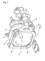
- Fig. 1 is a perspective view showing the whole of a light source according to a first embodiment of the invention.
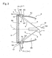
- Fig. 2 is a sectional view showing a main portion of the light source according to the first embodiment.
- Fig. 3 is an exploded perspective view showing an attachment state of a protective wall in the light source according to the first embodiment.
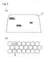
- Figs. 4A and 4B are enlarged plan views showing the whole and a part of a mesh in the light source according to the first embodiment.
- a light source 2 is roughly composed of a lamp housing 4, a concave mirror 6, a light permeable member 8, and a lamp 10.
- the lamp housing 4 includes a frame part 4A which opens in the front and back direction and sidewall parts 4B connecting to this frame part 4A, and its whole is formed of a high heat-resistant member having a C-shaped section.
- a frame part 4A which opens in the front and back direction and sidewall parts 4B connecting to this frame part 4A, and its whole is formed of a high heat-resistant member having a C-shaped section.
- through-windows 4b On the both sidewall parts 4B of the lamp housing 4, through-windows 4b (Only one is shown.) corresponding to permeable ports (described later) of the concave mirror 6 are provided.
- the lamp 10 is composed of a high pressure mercury lamp having a luminous tube 10A made of vitreous silica, and housed in the concave mirror 6. Inside the luminous tube 10A, a pair of electrodes (not shown) are provide along an imaginary axial line L (lamp optical axis) of a reflecting part 6C. When discharge is performed between these electrodes, a luminous part is formed between these electrodes, and light is emitted from the lamp 10.
- a metal halide lamp, a xenon lamp, or another lamp may be used as the lamp 10.
- the light emitted from the lamp 10 is reflected at the reflecting part 6C of the concave mirror 6, and this reflected light passes through the light permeable member 8 and is issued.
- the concave mirror 6, as shown in Fig. 1, is attached into the lamp housing 4. Further, as shown in Fig. 2, forward of the concave mirror 6 (in the light emitted direction), an opening part 6A is provided. Further, the concave mirror 6 has a space 6B communicating with this opening part 6A.
- the opening part 6A of the concave mirror 6 is closed by the light permeable member 8.
- the light permeable member 8 is formed of a high heat-resistant member that is hard.
- the reflecting part 6C having a radial section is provided.
- the reflecting part 6C is constituted so as to reflect the light emitted from the lamp 10 and emit the reflected light nearly in parallel to the imaginary axial line (lamp optical axis) L of the reflecting part 6C.
- a non-reflecting part 6D connecting to the reflecting part 6C is provided.
- permeable ports 6E, 6F passing through the non-reflecting parts 6D are provided.
- the permeable ports 6E, 6F are arranged, nearly opposed to each other with the lamp optical axis L between.
- meshes 12 covering the permeable ports 6E, 6F are attached by thermosetting adhesive or heat resistant adhesive. It is preferable that the adhesive strength of the mesh 12 is set to such a level that the mesh does peel off by collision between the mesh 12 and broken pieces of the lamp (glass) made by a burst of the lamp 10.
- impulse force of the lamp broken piece is about 4kg in relation to the lamp broken piece of 0.2g, and the adhesive strength is set to such a level that the adhesive strength can resist this impulse force.
- the mesh 12 is formed of an etching mesh made of metal such as SUS and having the high opening rate.
- the opening width of the mesh 12 is set to 0.3 mm or less, and its thickness is set to 30 to 50 ⁇ m. It is preferable that the opening rate ⁇ of the mesh 12 is set to a value satisfying 70% ⁇ ⁇ ⁇ 90%.
- the opening rate ⁇ of the mesh 12 is 90% or less, mechanical strength of the mesh does not extremely lower.
- the good cooling effect and ventilation efficiency in the concave mirror 6 can be surely obtained. Therefore, heat density of the lamp can be reduced, so that high luminance and size reduction which recent lamps require can be met and elongation of the lifetime of the lamp can be realized.
- a cross mesh made of metal such as SUS, tungsten alloy, or steel; or a cross mesh made of plastics of thermosetting resin may be used.
- slits 6d 1 and 6d 2 for attaching a protective wall 14 are provided on an inner surface of the permeable port 6E, 6F, as shown in Fig. 3, slits 6d 1 and 6d 2 for attaching a protective wall 14 are provided. End edges of the protective wall 14 are attached to the slits 6d 1 and 6d 2 with the thermosetting adhesive or the high heat resistant adhesive.
- This protective wall 14 is, in whole, formed of a high heat-resistant member composed of a thin piece made of SUS or synthetic resin that is parallel to aback surface of the light permeable member 8.
- the height of the protective wall 14 is set to such a dimension that the light emitted from the lamp is not intercepted.
- the protective 14 may be attached into the permeable port 6E, 6F not with the adhesive but by a mechanical method such as forcing.
- the protective wall 14 is arranged in a position where direct collision between the mesh 12 and broken pieces of the lamp made by a burst of the lamp 10 is prevented. Namely, the protective wall 14 is arranged, in the permeable port 6E, 6F, in a portion P1 where the mesh 12 and an extension line a 1 of an imaginary line a connecting a center part O of the lamp 10 (center part of a luminous part formed into the luminous tube 10A) and an opening edge Q1 near the lamp of the permeable port 6E, 6F intersect.
- the protective wall 14 is arranged on the opening edge Q1 side near the lamp of the permeable port 6E, 6F from the portion P1 where the extension line a 1 and the mesh 12 intersect, the direct collision of the broken pieces of the lamp with the mesh 12 can be prevented.
- the protective wall 14 is arranged in a position where also direct collision between the mesh 12 and broken pieces of the lamp that have bound by the collision with the light permeable member 8 caused by the burst of the lamp 10 is prevented.
- the protective wall 14 is arranged, in the permeable port 6E, 6F, in a portion P2 where the mesh and a third imaginary line c that is line-symmetrical about a second imaginary line b connecting the center part O of the lamp 10 and a position Q2, on the back surface of the light permeable member 8, which is distant from a mesh surface by a half length of a total length of the protective wall 14 intersect.
- line of line-symmetry means "an imaginary line on the same plane as the second imaginary line b and the third imaginary line c, which is a normal passing the intersection point Q2, on the back surface of the light permeable member 8, of the second imaginary line b and the third imaginary line c". Therefore, in case that the lamp broken pieces that have scattered, collides with the light permeable member 8 and bounded, these lamp broken pieces are received by a front surface of the protective wall 14, so that the direct collision of the lamp broken pieces with the mesh 12 is prevented.
- the protective wall 14 is arranged on the light permeable member side 8 of the portion P2 where the third imaginary line c and the mesh 12 intersect, the direct collision between the mesh 12 and the broken pieces of the lamp that have bound by the collision with the light permeable member 8 can be prevented.
- the direct collision of the lamp broken pieces with the mesh 12 can be prevented by the protective wall 14. Therefore, a mesh having the comparatively high opening rate can be used, and the good cooling effect and ventilation efficiency in the concave mirror 6 can be obtained.
- heat density of the lamp 10 can be reduced, so that high luminance and size reduction which recent lamps require can be met and elongation of the lifetime of the lamp 10 can be realized.
- the blowing amount to the lamp 10 by the cooling fun can be reduced. Therefore, the number of turns of the cooling fan can be reduced, so that the noise made by the cooling fan can be reduced.
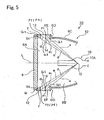
- Fig. 5 is a sectional view showing a main portion of a light source according to a second embodiment of the invention.
- Fig. 6 is an exploded perspective view showing an attachment state of a protective wall and an auxiliary protective wall in the light source according to the second embodiment of the invention.
- the same members as those in Figs. 2 and 3 are denoted by the same reference numerals, and their detailed description is omitted.
- the protective wall 14 is provided in the position where it is possible to prevent both lamp broken pieces that have scattered toward the mesh 12 and lamp broken pieces that have collided with the light permeable member 8 and bounded from directly colliding with the mesh 12.
- the light source shown in this embodiment is characterized in that: a protective wall 14 is provided in a position where it is possible to prevent lamp broken pieces that have scattered toward a mesh 12 from directly colliding with the mesh 12; and further, an auxiliary protective wall for protecting the mesh is arranged in a position where the direct collision between the mesh, and the lamp broken pieces scattering due to the burst of the lamp and the lamp broken pieces that have collided with a light permeable member and bounded is prevented.
- Other constitution is similar to that in the first embodiment.
- a light source 50 in this embodiment includes a concave mirror 52, a light permeable member 8 and a lamp 10.
- slits 6d 1 , 6d 2 for attaching the protective wall 14 and slits 6d 3 , 6d 4 for attaching the auxiliary protective wall 54 are provided.
- the heights of the protective wall 14 and the auxiliary protective wall 54 are set to such a dimension that the light emitted from the lamp is not intercepted.
- This protective wall 14 is, in whole, formed of a high heat-resistant member composed of a thin piece made of SUS or synthetic resin that is parallel to a back surface of the light permeable member 8. Further, the protective wall 14 is arranged in a position where direct collision between the mesh 12 and broken pieces of the lamp made by a burst of the lamp 10 is prevented.
- the protective wall 14 is arranged, in the permeable port 6E, 6F, in a portion P1 where the mesh 12 and an extension line a 1 of an imaginary line a connecting a center part O of the lamp 10 and an opening edge Q1 near the lamp of the permeable port 6E, 6F intersect. Therefore, even in case that a luminous tube 10A bursts due to increase of vapor pressure during lighting of the lamp 10, and broken pieces of the lamp scatter toward the mesh 12, these broken pieces of the lamp are received by the protective wall 14, so that the direct collision of the broken pieces of the lamp with the mesh 12 is prevented.
- auxiliary protective wall 54 End edges of the auxiliary protective wall 54 are attached to the slits 6d 3 and 6d 4 with the thermosetting adhesive or the high heat-resistant adhesive.
- This auxiliary protective wall 54 is, in whole, formed of a high heat-resistant member composed of a thin piece made of SUS or synthetic resin that is parallel to the back surface of the light permeable member 8. Further, the auxiliary protective wall 54 is arranged in a position where the direct collision between the mesh 12 and the broken pieces of the lamp made by the burst of the lamp 10 is prevented.
- the auxiliary protective wall 54 is arranged, in the permeable port 6E, 6F, in a portion P3 where the mesh 12 and an extension line d 1 of a fourth imaginary line d connecting the center part O of the lamp 10 and a leading end Q3 of the protective wall 14 intersect. Therefore, even in case that the luminous tube 10A bursts due to increase of vapor pressure during lighting of the lamp 10, and the broken pieces of the lamp scatter toward the mesh 12, these broken pieces of the lamp are received by a back surface of the auxiliary protective wall 54, so that the direct collision of the broken pieces of the lamp with the mesh 12 is prevented.
- auxiliaryprotective wall 54 is arranged on the protective wall 14 side of the permeable port 6E, 6F from the portion P3 where the second extension line d 1 and the mesh 12 intersect, the direct collision of the broken pieces of the lamp with the mesh 12 can be prevented.
- the auxiliary protective wall 54 is arranged in a position where the direct collision between the mesh 12 and the lamp broken pieces that have collided with the light permeable member 8 due to the burst of the lamp and bounded can be also prevented.
- the auxiliary protective wall 54 is, in the permeable ports 6E, 6F, in a portion P4 where the mesh 12 and a seventh imaginary line f that is line-symmetrical about a sixth imaginary line e connecting the center part O of the lamp 10 and a position Q4, on the back surface of the light permeable member 8, which is distant from the mesh surface by a half length of a total length of the auxiliary protective wall 54 that is closest to the light permeable member 8 intersect.
- line of line-symmetry means "an imaginary line on the same plane as the sixth imaginary line e and the seventh imaginary line f, which is a normal passing the intersection point Q4, on the back surface of the light permeable member 8, of the sixth imaginary line e and the seventh imaginary line f". Accordingly, also in case that the lamp broken pieces that have scattered collide with the light permeable member 8 and bound, these broken pieces of the lamp are received by a front surface of the auxiliary protective wall 54, so that the collision of the broken pieces of the lamp with the mesh 12 is prevented.
- auxiliary protective wall 54 is arranged on the light permeable member 8 side of the portion P4 where the seventh imaginary line f and the mesh 12 intersect, the direct collision between the mesh 12 and the lamp broken pieces that have collided with the light permeable member 8 and bounded can be prevented.
- the protective wall 14 and the auxiliary protective wall 54 As described above, in the embodiment, by the protective wall 14 and the auxiliary protective wall 54, the direct collision of the lamp broken pieces with the mesh 12 can be prevented, so that the similar effect to that in the first embodiment can be obtained.
- auxiliary protective walls 82, 84 may be provided on a light permeable member 8 side of a protective wall 14 in parallel.
- This embodiment is different from the second embodiment in that the plural auxiliary protective walls 82, 84 are provided.
- Other constitution is similar to that in the second embodiment.
- Fig. 7 is a sectional view showing a main portion of a light source according to a third embodiment. In Fig. 7, the same members as those in Fig. 5 are denoted by the same reference numerals, and their detailed description is omitted.
- a light source 70 includes a concave mirror 72, a light permeable member 8 and a lamp 10.
- the auxiliary protective walls 82 and 84 are arranged in positions where direct collision of lamp broken pieces made by a burst of the lamp 10 with a mesh 12 is prevented. Namely, the auxiliary protective wall 82 on the protective wall 14 side is arranged, in permeable port 6E, 6F, in a portion P3 where the mesh 12 and an extension line d 1 of a fourth imaginary line d connecting a center part O of the lamp 10 and a leading end Q3 of the protective wall 14 intersect.
- the auxiliary protective wall 84 on the light permeable member 8 side is arranged in a portion P5 where the mesh 12 and a fifth extension line K 1 of a twelfth imaginary line K connecting the center part O of the lamp 10 and a leading end Q5 of the auxiliary protective wall 82 intersect. Therefore, even in case that a luminous tube 10A bursts due to increase of vapor pressure during lighting of the lamp 10, and the broken pieces of the lamp scatter toward the mesh 12, these broken pieces of the lamp are received by back surfaces of the auxiliary protective walls 82 and 84, so that the direct collision of the broken pieces of the lamp with the mesh 12 is prevented.
- the auxiliary protective wall 84 on the light permeable member 8 side is arranged in a position where the direct collision between the mesh 12 and the broken pieces of the lamp 10 that have bound by the collision with the light permeable member 8 due to the burst of the lamp 10 can be also prevented.
- the auxiliary protective wall 84 is arranged in a portion P6 where the mesh 12 and a fourteenth imaginary line n that is line-symmetrical about a thirteenth imaginary line m connecting the center part O of the lamp 10 and a position Q6, on the back surface of the light permeable member 8, which is distant from the mesh 12 surface byahalf length of a total length of the auxiliary protective wall 84 intersect.
- line of line-symmetry means "an imaginary line on the same plane as the thirteenth imaginary line m and the fourteenth imaginary line n, which is a normal passing the intersection point Q6, on the back surface of the light permeable member 8, of the thirteenth imaginary line m and the fourteenth imaginary line n". Therefore, even in case that the broken pieces of the lamp that have scattered collide with the light permeable member 8 and bound, these broken pieces of the lamp are received by a front surface of the auxiliary protective wall 84, so that the collision of the broken pieces of the lamp with the mesh 12 is prevented.
- the protective wall 14, and the auxiliary protective walls 54, 82, 84 are formed separately from the concave mirrors 6, 52, 72 has been described. However, they may be integrally formed.
- Fig. 8 is a diagram showing, as one example, a state where the protective wall 14 and the auxiliary protective walls 54 in the second embodiment are formed integrally with the concave mirror 72.
- manufacture of the protective wall 14 and the auxiliary protective wall 54 is performed simultaneously with manufacture of the concave mirror 72.
- a manufacturing cost can be reduced.
- the protective wall 14 and the auxiliary protective walls 54, 82, 84 are attached in the grooves 6d 1 to 6d 4 of the concave mirrors 6, 52, 72. However, they may be provided for the concave mirror through an attachment spacer.
- Fig. 9 is a diagram showing, as one example, a state where the protective wall 14 and the auxiliary protective wall 54 in the second embodiment are arranged in the permeable port 6E if the concave mirror through an attachment spacer 88.
- the attachment part such as the groove 6d 1 to 6d 4 in the concave mirror in order to attach the protective wall 14 and the auxiliary protective wall 54 to the concave mirror (inner surface of the permeable port 6E), so that the manufacturing cost can be reduced.
- the protective wall 14 is parallel to the light permeable member 8. However, by inclining this protective wall in relation to the back surface of the light permeable member 8, it is possible to give a function as a rectifying wall of air flowing into the concave mirror 6 to the protective wall 14.
- Fig. 10 is a diagram showing, as one example, a state where the protective wall 86 in the second embodiment is inclined, as the rectifying wall, in relation to the back surface of the light permeable member 8.
- airflow is guided into the concave mirror 72 along the protective wall 86.
- cool wind flowing from the outside of the concave mirror 72 through the permeable ports 6D, 6E into the concave mirror 72 can be rectified.
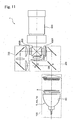
- Fig. 11 is a plan view showing an example in which the light sources 6, 50, 70 according to the first to sixth embodiments described above are applied to a projector.
- a projector represented by reference numeral 1 includes an illuminating optical system 100, a color separation optical system 200, a relay optical system 300, three electro-optic modulating elements 400R, 400G, 400B, a cross dichroic prism 500, and a projecting lens 600.
- the components of each optical system are arranged nearly in the horizontal direction, centering around the cross dichroic prism 500.
- the light emitted from the illuminating optical system 100 is separated into light of each color of red R, green G, and blue B, and these color lights are respectively guided to light bulbs 400R, 400G, 400B to be modulated according to image signals. Thereafter, each color light is compounded by the cross dichroic prim 500, enlarged by the projecting lens 600, and displayed on a screen.
- the constitution and functions of other optical systems than the light sources 6, 50, 70 have been described in JP-A-10-177151.
- the illuminating optical system 100 includes the light sources 6, 50, 70 in the first to sixth embodiments. Therefore, according to the projector 1 in this embodiment, the high luminance and the size reduction which the recent lamps require can be met, and the elongation of the lifetime of the lamp can be realized.
- flowing path resistance of ventilation to the lamp can be reduced. Therefore, the number of turns of the cooling fan can be reduced, and the noise can be reduced, increasing the cooling performance.
- the light source of the invention is applied to the three-plate type projector using the three electro-optic modulating elements.
- the invention can be applied also to a projector having one, two, or four or more electro-opticmodulating elements.
- electro-optic modulating element various elements such as a liquid crystal panel and a modulation element in which a picture element is composed by plural mirrors can be used.
- the projector there are a front type projector in which a projected image is observed from the same direction as a direction in which an image is projected, and a rear type projector in which a projected image is observed from the opposite direction to a direction in which an image is projected.
- the light source of the invention can be applied to any type projector.
Landscapes
- Engineering & Computer Science (AREA)
- Multimedia (AREA)
- Signal Processing (AREA)
- Physics & Mathematics (AREA)
- General Physics & Mathematics (AREA)
- Computer Security & Cryptography (AREA)
- Projection Apparatus (AREA)
- Non-Portable Lighting Devices Or Systems Thereof (AREA)
Abstract
Description
Claims (18)
- A light source, including a lamp which emits the light, a concave mirror which reflects the light emitted from said lamp and has an opening part which issues the light, and a light permeable member which covers the opening part of said concave mirror, characterized in that said convex mirror includes a permeable port, a mesh arranged in a position where it covers the permeable port, and a protective wall for protecting said mesh, which is arranged in a position where direct collision between the mesh and broken pieces of the lamp made by a burst of the lamp is prevented.
- The light source according to Claim 1, wherein said protective wall is arranged, in said permeable port, in a portion where said mesh and an extension line of an imaginary line connecting a center part of said lamp and an opening edge near the lamp of said permeable port intersect, or on the opening edge side near said lamp of said portion.
- The light source according to Claim 1 or 2, wherein said protective wall is arranged in a position where the direct collision between said mesh and said lamp broken pieces that have bounced by the collision with said light permeable member is prevented.
- The light source according to any of Claims 1 to 3, wherein
saidprotective wall is arranged, in said permeable port, in a portion where the mesh and a third imaginary line that is line-symmetrical about a second imaginary line connecting the centerpart of said lamp and a position, on a back surface of said light permeable member, which is distant from the mesh surface by a half length of a total length of the protective wall intersect; or on said light permeable member side of said portion. - The light source according to any of Claims 1 to 4, wherein the height of the protective wall is set to a dimension by which an emergent ray from the lamp is not intercepted.
- The light source according to any of Claims 1 to 5, wherein said protective wall inclines in relation to the back surface of said light permeable member.
- The light source according to any of Claims 1 to 6, wherein
said protective wall is integrally provided for said concave mirror. - The light source according to any of Claims 1 to 7, wherein said protective wall is attached to said concave mirror through an attachment spacer.
- The light source according to any of Claims 1 to 8, wherein
said concave mirror has further an auxiliary protective wall for protecting said mesh. - The light source according to Claim 9, wherein said auxiliary protective wall is arranged in a position where the direct collision between said mesh and lamp broken pieces scattering due to the burst of said lamp is prevented.
- The light source according to Claim 9 or 10, wherein said auxiliary protective wall is arranged, in said permeable port, in a portion where said mesh and an extension line of a fourth imaginary line connecting the center part of said lamp and a leading end of said protective wall intersect, or on said protective wall side of said portion.
- The light source according to any of Claims 9 to 11, wherein as said auxiliary protective wall, the plural auxiliary protective walls are arranged on the light permeable member side of said protective wall in parallel; and
said auxiliary protective wall on said light permeable member side is arranged in a portion where said mesh and an extension line of a fifth imaginary line connecting the center part of said lamp and a leading end of said auxiliary protective wall on said protective wall side intersect, or on the protective wall side of said portion. - The light source according to any of Claims 9 to 12, wherein said auxiliary protective wall is arranged in a position where the direct collision between said mesh and said lamp broken pieces that have bounced by the collision with said light permeable member is prevented.
- The light source according to Claim 13, wherein said auxiliary protective wall is arranged, in said permeable port, in a portion where said mesh and a seventh imaginary line that is line-symmetrical about a sixth imaginary line connecting the center part of said lamp and a position, on the back surface of said light permeable member, which is distant from the mesh surface by a half length of a total length of the auxiliary protective wall that is closest to the light permeable member intersect; or on said light permeable member side of said portion.
- The light source according to any of Claims 9 to 14, wherein the height of the auxiliary protective wall is set to a dimension by which an emergent light from the lamp is not intercepted.
- The light source according to any of Claims 9 to 15, wherein, said auxiliary protective wall is provided integrally for said concave mirror.
- The light source according to any of Claims 8 to 15, wherein said auxiliary protective wall is provided for said concave mirror through an attachment spacer.
- A projector comprising the light source according to any of Claims 1 to 17, an electro-optic modulating unit which modulates the emergent ray from said light source according to image signals, and a projecting optical system which projects and displays the modulated light from said electro-optic modulating unit.
Applications Claiming Priority (3)
| Application Number | Priority Date | Filing Date | Title |
|---|---|---|---|
| JP2003042666 | 2003-02-20 | ||
| JP2003042666 | 2003-02-20 | ||
| PCT/JP2004/001953 WO2004074927A1 (en) | 2003-02-20 | 2004-02-19 | Light source and projector having the same |
Publications (2)
| Publication Number | Publication Date |
|---|---|
| EP1602971A1 true EP1602971A1 (en) | 2005-12-07 |
| EP1602971A4 EP1602971A4 (en) | 2007-10-31 |
Family
ID=32905358
Family Applications (1)
| Application Number | Title | Priority Date | Filing Date |
|---|---|---|---|
| EP04712720A Withdrawn EP1602971A4 (en) | 2003-02-20 | 2004-02-19 | LIGHT SOURCE AND PROJECTOR COMPRISING THE SAME |
Country Status (7)
| Country | Link |
|---|---|
| US (1) | US7052147B2 (en) |
| EP (1) | EP1602971A4 (en) |
| JP (1) | JP4096974B2 (en) |
| KR (1) | KR100714536B1 (en) |
| CN (1) | CN100472319C (en) |
| TW (1) | TWI234687B (en) |
| WO (1) | WO2004074927A1 (en) |
Cited By (1)
| Publication number | Priority date | Publication date | Assignee | Title |
|---|---|---|---|---|
| US20110013155A1 (en) * | 2009-07-15 | 2011-01-20 | Qisda Corporation | Projector |
Families Citing this family (22)
| Publication number | Priority date | Publication date | Assignee | Title |
|---|---|---|---|---|
| JP2005316177A (en) * | 2004-04-28 | 2005-11-10 | Toshiba Corp | Lamp unit and projection type display device |
| US7125125B2 (en) * | 2004-09-15 | 2006-10-24 | Coretronic Corporation | Burner debris collection apparatus for projectors |
| CN101107563A (en) * | 2005-01-21 | 2008-01-16 | 松下电器产业株式会社 | Light source unit, light source device and projection display device |
| EP1688787A1 (en) * | 2005-02-07 | 2006-08-09 | Coretronic Corporation | Burner debris collection apparatus for projectors |
| TWD114878S1 (en) * | 2005-09-02 | 2007-01-01 | 精工愛普生股份有限公司 | Projector Bulbs |
| JP4979237B2 (en) * | 2006-01-19 | 2012-07-18 | 三菱電機株式会社 | Light source device |
| JP2007248760A (en) * | 2006-03-15 | 2007-09-27 | Funai Electric Co Ltd | projector |
| USD561232S1 (en) * | 2006-05-02 | 2008-02-05 | Seiko Epson Corporation | Lamp for projector |
| AU2007306936B2 (en) * | 2006-10-12 | 2014-02-06 | The University Of Queensland | Compositions and methods for modulating immune responses |
| JP4259571B2 (en) * | 2006-11-22 | 2009-04-30 | 船井電機株式会社 | projector |
| TWD122600S1 (en) * | 2007-03-01 | 2008-04-21 | 精工愛普生股份有限公司 | Lamp for projector |
| TWD121892S1 (en) * | 2007-03-02 | 2008-03-11 | 精工愛普生股份有限公司 | Lamp for projector |
| US9140968B2 (en) * | 2007-06-29 | 2015-09-22 | Seiko Epson Corporation | Projection device particle-containment shield |
| TWD127301S1 (en) * | 2007-07-12 | 2009-02-01 | 精工愛普生股份有限公司 | Lamp for projector |
| USD591322S1 (en) * | 2007-07-12 | 2009-04-28 | Seiko Epson Corporation | Lamp for projector |
| JP4759758B2 (en) * | 2007-11-19 | 2011-08-31 | Necディスプレイソリューションズ株式会社 | Projection display |
| TWD126878S1 (en) * | 2007-12-26 | 2009-01-01 | 精工愛普生股份有限公司 | Lamp for projector |
| TWD128538S1 (en) * | 2008-02-27 | 2009-05-01 | 精工愛普生股份有限公司 | Lamp for projector |
| CN101619841B (en) * | 2008-06-30 | 2011-01-26 | 鸿富锦精密工业(深圳)有限公司 | Bulb explosion-proof device |
| TWD130839S1 (en) * | 2008-07-31 | 2009-09-11 | 精工愛普生股份有限公司 | Lamp for projector |
| TWD135179S1 (en) * | 2009-04-09 | 2010-06-01 | 精工愛普生股份有限公司 | Lamp unit for projector |
| USD616912S1 (en) * | 2009-06-05 | 2010-06-01 | Seiko Epson Corporation | Lamp for projector |
Family Cites Families (15)
| Publication number | Priority date | Publication date | Assignee | Title |
|---|---|---|---|---|
| JPH1048747A (en) * | 1996-08-06 | 1998-02-20 | Hitachi Ltd | Cooling system for projection type liquid crystal display |
| JP3298437B2 (en) | 1996-12-18 | 2002-07-02 | セイコーエプソン株式会社 | Optical element, polarized illumination device and projection display device |
| JP3275755B2 (en) | 1997-01-31 | 2002-04-22 | ウシオ電機株式会社 | Light irradiation unit |
| JPH10254061A (en) | 1997-03-07 | 1998-09-25 | Seiko Epson Corp | Light source device and projection display device |
| JP3878325B2 (en) * | 1998-04-21 | 2007-02-07 | 株式会社東芝 | Cold water equipment for ventilation and air conditioning in nuclear facilities |
| JP2000200511A (en) | 1998-10-30 | 2000-07-18 | Phoenix Denki Kk | Discharge lamp |
| JP3572982B2 (en) * | 1999-02-19 | 2004-10-06 | セイコーエプソン株式会社 | Projection display device |
| US6398367B1 (en) * | 1999-03-05 | 2002-06-04 | Seiko Epson Corporation | Light source device and projector using the light source device |
| JP4225626B2 (en) * | 1999-04-02 | 2009-02-18 | 三菱電機株式会社 | Light source device |
| JP2001125195A (en) | 1999-10-27 | 2001-05-11 | Hitachi Ltd | Light source device and display device using the same |
| JP3667588B2 (en) | 2000-03-10 | 2005-07-06 | Necビューテクノロジー株式会社 | Lamp house and its projector device |
| JP3557165B2 (en) | 2000-11-09 | 2004-08-25 | 三洋電機株式会社 | Light source device and projection type video display device having the same |
| JP2002202562A (en) | 2000-12-27 | 2002-07-19 | Toshiba Corp | Projector safety devices |
| JP3512745B2 (en) | 2001-01-18 | 2004-03-31 | 松下電器産業株式会社 | Light source device and projector using the same |
| JP3956648B2 (en) | 2001-05-30 | 2007-08-08 | セイコーエプソン株式会社 | Light source device, lamp unit and projector |
-
2004
- 2004-02-18 US US10/779,666 patent/US7052147B2/en not_active Expired - Lifetime
- 2004-02-19 KR KR1020057015195A patent/KR100714536B1/en not_active Expired - Fee Related
- 2004-02-19 CN CNB2004800045030A patent/CN100472319C/en not_active Expired - Fee Related
- 2004-02-19 EP EP04712720A patent/EP1602971A4/en not_active Withdrawn
- 2004-02-19 JP JP2005502776A patent/JP4096974B2/en not_active Expired - Fee Related
- 2004-02-19 WO PCT/JP2004/001953 patent/WO2004074927A1/en not_active Ceased
- 2004-02-20 TW TW093104299A patent/TWI234687B/en active
Cited By (2)
| Publication number | Priority date | Publication date | Assignee | Title |
|---|---|---|---|---|
| US20110013155A1 (en) * | 2009-07-15 | 2011-01-20 | Qisda Corporation | Projector |
| US9016874B2 (en) * | 2009-07-15 | 2015-04-28 | Qisda Corporation | Projector |
Also Published As
| Publication number | Publication date |
|---|---|
| JP4096974B2 (en) | 2008-06-04 |
| US20040233399A1 (en) | 2004-11-25 |
| CN100472319C (en) | 2009-03-25 |
| US7052147B2 (en) | 2006-05-30 |
| KR20050101556A (en) | 2005-10-24 |
| KR100714536B1 (en) | 2007-05-07 |
| WO2004074927A1 (en) | 2004-09-02 |
| TW200426490A (en) | 2004-12-01 |
| CN1751265A (en) | 2006-03-22 |
| JPWO2004074927A1 (en) | 2006-06-01 |
| EP1602971A4 (en) | 2007-10-31 |
| TWI234687B (en) | 2005-06-21 |
Similar Documents
| Publication | Publication Date | Title |
|---|---|---|
| EP1602971A1 (en) | Light source and projector having the same | |
| US5634704A (en) | Light-source device and projection-type display device | |
| EP0239007B1 (en) | Liquid crystal projector | |
| US5135300A (en) | Projection color display apparatus | |
| US7059752B2 (en) | Vehicular infrared light radiating lamp | |
| JP2007156270A (en) | Light source device and projection type image display device | |
| US5993008A (en) | Front liquid crystal display projector | |
| JPH10254061A (en) | Light source device and projection display device | |
| US5123729A (en) | Projection display device | |
| US7040763B2 (en) | Image display device | |
| CN100374902C (en) | projection display device | |
| KR19980081503A (en) | Rear Projection Display and Screen Unit | |
| US20060279711A1 (en) | Projection display | |
| EP1136867B1 (en) | Optical apparatus and projection type display apparatus using the same | |
| US7670011B2 (en) | Projector assembly provided with an auxiliary device | |
| US20070064432A1 (en) | Light-source lamp | |
| JP2007065520A (en) | Image display device | |
| CN212341498U (en) | Prism assembly and digital light processing prism equipment | |
| US7607787B2 (en) | Light source unit and projector system | |
| JPH0450937A (en) | Liquid crystal projector device | |
| JP3022144B2 (en) | LCD projector | |
| JP2006163353A (en) | Lighting system | |
| JP2008102168A (en) | projector | |
| KR20080022385A (en) | Projector | |
| JPH06265889A (en) | Projection type display device |
Legal Events
| Date | Code | Title | Description |
|---|---|---|---|
| PUAI | Public reference made under article 153(3) epc to a published international application that has entered the european phase |
Free format text: ORIGINAL CODE: 0009012 |
|
| 17P | Request for examination filed |
Effective date: 20050715 |
|
| AK | Designated contracting states |
Kind code of ref document: A1 Designated state(s): AT BE BG CH CY CZ DE DK EE ES FI FR GB GR HU IE IT LI LU MC NL PT RO SE SI SK TR |
|
| AX | Request for extension of the european patent |
Extension state: AL LT LV MK |
|
| DAX | Request for extension of the european patent (deleted) | ||
| RBV | Designated contracting states (corrected) |
Designated state(s): DE FR GB |
|
| A4 | Supplementary search report drawn up and despatched |
Effective date: 20071001 |
|
| RIC1 | Information provided on ipc code assigned before grant |
Ipc: G03B 21/14 20060101ALI20070926BHEP Ipc: H04N 9/31 20060101AFI20070926BHEP |
|
| 17Q | First examination report despatched |
Effective date: 20080418 |
|
| GRAP | Despatch of communication of intention to grant a patent |
Free format text: ORIGINAL CODE: EPIDOSNIGR1 |
|
| STAA | Information on the status of an ep patent application or granted ep patent |
Free format text: STATUS: THE APPLICATION IS DEEMED TO BE WITHDRAWN |
|
| 18D | Application deemed to be withdrawn |
Effective date: 20091229 |