EP1602898B1 - High resolution hall effect position sensor with a high immunity against electromagnetic noise - Google Patents
High resolution hall effect position sensor with a high immunity against electromagnetic noise Download PDFInfo
- Publication number
- EP1602898B1 EP1602898B1 EP05104696A EP05104696A EP1602898B1 EP 1602898 B1 EP1602898 B1 EP 1602898B1 EP 05104696 A EP05104696 A EP 05104696A EP 05104696 A EP05104696 A EP 05104696A EP 1602898 B1 EP1602898 B1 EP 1602898B1
- Authority
- EP
- European Patent Office
- Prior art keywords
- signals
- electric motor
- hall effect
- frequency
- magnetic field
- Prior art date
- Legal status (The legal status is an assumption and is not a legal conclusion. Google has not performed a legal analysis and makes no representation as to the accuracy of the status listed.)
- Expired - Fee Related
Links
- 230000005355 Hall effect Effects 0.000 title claims description 22
- 230000036039 immunity Effects 0.000 title description 5
- 230000005291 magnetic effect Effects 0.000 claims description 33
- 238000012545 processing Methods 0.000 claims description 14
- 238000001514 detection method Methods 0.000 claims description 11
- 230000005294 ferromagnetic effect Effects 0.000 claims description 9
- 238000000034 method Methods 0.000 claims description 8
- 238000013507 mapping Methods 0.000 claims description 7
- XAGFODPZIPBFFR-UHFFFAOYSA-N aluminium Chemical compound [Al] XAGFODPZIPBFFR-UHFFFAOYSA-N 0.000 claims description 4
- 229910052782 aluminium Inorganic materials 0.000 claims description 4
- 239000004411 aluminium Substances 0.000 claims description 4
- 238000004891 communication Methods 0.000 claims description 3
- 229910001172 neodymium magnet Inorganic materials 0.000 claims description 2
- 238000012360 testing method Methods 0.000 claims description 2
- 230000002093 peripheral effect Effects 0.000 claims 2
- 230000000063 preceeding effect Effects 0.000 claims 2
- 238000005259 measurement Methods 0.000 description 5
- 238000010586 diagram Methods 0.000 description 2
- 238000001228 spectrum Methods 0.000 description 2
- 230000032683 aging Effects 0.000 description 1
- 230000003321 amplification Effects 0.000 description 1
- 230000007613 environmental effect Effects 0.000 description 1
- 239000003302 ferromagnetic material Substances 0.000 description 1
- 230000010354 integration Effects 0.000 description 1
- 238000000691 measurement method Methods 0.000 description 1
- 230000005405 multipole Effects 0.000 description 1
- 238000003199 nucleic acid amplification method Methods 0.000 description 1
Images
Classifications
-
- G—PHYSICS
- G01—MEASURING; TESTING
- G01D—MEASURING NOT SPECIALLY ADAPTED FOR A SPECIFIC VARIABLE; ARRANGEMENTS FOR MEASURING TWO OR MORE VARIABLES NOT COVERED IN A SINGLE OTHER SUBCLASS; TARIFF METERING APPARATUS; MEASURING OR TESTING NOT OTHERWISE PROVIDED FOR
- G01D5/00—Mechanical means for transferring the output of a sensing member; Means for converting the output of a sensing member to another variable where the form or nature of the sensing member does not constrain the means for converting; Transducers not specially adapted for a specific variable
- G01D5/12—Mechanical means for transferring the output of a sensing member; Means for converting the output of a sensing member to another variable where the form or nature of the sensing member does not constrain the means for converting; Transducers not specially adapted for a specific variable using electric or magnetic means
- G01D5/14—Mechanical means for transferring the output of a sensing member; Means for converting the output of a sensing member to another variable where the form or nature of the sensing member does not constrain the means for converting; Transducers not specially adapted for a specific variable using electric or magnetic means influencing the magnitude of a current or voltage
- G01D5/142—Mechanical means for transferring the output of a sensing member; Means for converting the output of a sensing member to another variable where the form or nature of the sensing member does not constrain the means for converting; Transducers not specially adapted for a specific variable using electric or magnetic means influencing the magnitude of a current or voltage using Hall-effect devices
- G01D5/145—Mechanical means for transferring the output of a sensing member; Means for converting the output of a sensing member to another variable where the form or nature of the sensing member does not constrain the means for converting; Transducers not specially adapted for a specific variable using electric or magnetic means influencing the magnitude of a current or voltage using Hall-effect devices influenced by the relative movement between the Hall device and magnetic fields
Definitions
- This invention refers to the field of position and movement sensors.
- Hall effect sensors for the detection of the spectrum and intensity of magnetic fields is known in the art.
- the operation of these sensors is based on the measurement of the interference that the incident magnetic field causes to the electrical current within the sensor and requires their positioning so as to be affected only by the magnetic field source that needs to be measured.
- magnetic field generated for example inside an electric motor
- magnetosensitive sensors - of operational variables such as, for example, the position or speed of rotation of a mechanical shaft
- Document USA4086519 discloses a Hall effect shaft angle position encoder employing a plurality of magnetic elements independent of any magnetic rotor of the electrical device and secured to the rotor outside the normal rotor elements of the device.
- Document US2002/0021124 discloses an angle sensor based on Hall effect sensors arranged in the area of the edge of the magnetic field concentrator.
- Document US6118271 discloses a position encoder for indicating the relative position between first and second relatively movable members wherein one of said members carries a multipole magnetic scale which generates a magnetic field which varies with position and wherein a saturable magnetic element is located in the positionally varying magnetic field.
- the saturable magnetic element is driven in and out saturation and outputs a signal which is used to determine the mutual angular position of said.
- the high degree of measurement accuracy given by the Hall effect sensors offers the possibility to effectively determine the operational variables of the electric motor
- the high level of electromagnetic noise produced inside the electric motor normally makes it unfeasible to achieve an appropriate positioning of the Hall sensor so as to be sufficiently immune to the magnetic fields which are not relevant to the measurement.
- This invention describes a position sensor with a high resolution Hall effect and high immunity against electromagnetic noise to be used for controlling electric motors and mechanical shafts.
- Said sensor comprises the mapping means of a magnetic field related to operational variables internal to an electric motor; detection devices of said magnetic field; acquisition and processing means of the signals produced by said magnetic field detection devices.
- a particular aim of the present invention is to disclose a device and a method for measuring operational variables of electric motors with the use of a position sensor employing a high resolution and high electromagnetic interference immunity Hall effect sensor, as described more fully in the claims below, which are an integral part of the present description.
- the device comprises a position sensor with a high resolution and high electromagnetic interference immunity Hall effect sensor to be used for controlling electric motors and mechanical shafts.
- said device comprises: mapping means of magnetic fields related to operational variables of an electric motor; detection means of said magnetic field; acquisition and processing means of the signals produced by said magnetic field detection means.
- said means for extracting information regarding the absolute electrical angular position from the output signals of the Hall effect sensors are shown in the block diagram in Fig. 2 , which include the following:
- the device may be completed with a self-calibration circuitry, if required, which is able, for instance, to allow proper operation even in case of parameter variations of the electronic and magnetic components caused by the ageing or altered environmental conditions in which the device operates.
- the non-ferromagnetic disk 10 is solidly connected with the electric motor shaft, the motion of which is to be analyzed in addition to the determination of the exact angular position of the rotor.
- the motion of which is to be analyzed in addition to the determination of the exact angular position of the rotor.
- the above-mentioned magnetic field mapping and detection means can be implemented within the same electric motor of which the operation parameters are being measured, without showing the problems mentioned above, and associated with the presence of a high level of electromagnetic noise generated inside the electric motor during its normal operation.
- the method for the determination of the angular position of the motor is carried out according to the following steps:
- the RTDC board is generally designed as to transform this information directly into the value of ⁇ which represents the measurement of the required angle, output through a negative feedback system.
- step d within the RTDC board, the two signals mentioned above are respectively multiplied by the cosine and by the sine of the angle ⁇ , thereby obtaining the following signals:
- x ⁇ 1 A ⁇ sin ⁇ ⁇ t ⁇ sin ⁇ ⁇ cos ⁇
- x ⁇ 2 A ⁇ sin ⁇ ⁇ t ⁇ cos ⁇ ⁇ sin ⁇
- a negative feedback system inside the RTDC board based on a Phase Locked Loop (PLL), quickly adjusts the value ⁇ of the counter so as to eliminate the angular error ( ⁇ - ⁇ ).
- PLL Phase Locked Loop
- the signal obtained in step d) of the method according to the present invention contains the information related to the absolute electrical angular position which is stored into the N bit counter of the RTDC board and can be output using several communication protocols, such as, for example, serial, parallel, incremental encoder emulation protocols etc.
Landscapes
- Physics & Mathematics (AREA)
- General Physics & Mathematics (AREA)
- Transmission And Conversion Of Sensor Element Output (AREA)
- Measurement Of Length, Angles, Or The Like Using Electric Or Magnetic Means (AREA)
Description
- This invention refers to the field of position and movement sensors.
- The use of Hall effect sensors for the detection of the spectrum and intensity of magnetic fields is known in the art.
- The operation of these sensors is based on the measurement of the interference that the incident magnetic field causes to the electrical current within the sensor and requires their positioning so as to be affected only by the magnetic field source that needs to be measured. When such magnetic field, generated for example inside an electric motor, has a shape which allows an indirect measurement - via magnetosensitive sensors - of operational variables such as, for example, the position or speed of rotation of a mechanical shaft, there may be a problem concerning the effective use of said sensors, which is very difficult especially when said sensors are inside the electric motor.
- Document
USA4086519 discloses a Hall effect shaft angle position encoder employing a plurality of magnetic elements independent of any magnetic rotor of the electrical device and secured to the rotor outside the normal rotor elements of the device. DocumentUS2002/0021124 discloses an angle sensor based on Hall effect sensors arranged in the area of the edge of the magnetic field concentrator. DocumentUS6118271 discloses a position encoder for indicating the relative position between first and second relatively movable members wherein one of said members carries a multipole magnetic scale which generates a magnetic field which varies with position and wherein a saturable magnetic element is located in the positionally varying magnetic field. The saturable magnetic element is driven in and out saturation and outputs a signal which is used to determine the mutual angular position of said. None of the above devices and apparatuses, in order for instance to implement very high quality motor control applications like high grade vectorial control, makes use, instead of the bare digitalization of the signal coming from each sensor, of the analog and continuous correlation between the truly analog outputs of a plurality of sensors devices to obtain a level of accuracy and an electromagnetic noise immunity which is compatible with integration of the sensor inside an electrical motor, obtaining very high precision and very high angular resolution. - As a matter of fact, if on the one hand the high degree of measurement accuracy given by the Hall effect sensors offers the possibility to effectively determine the operational variables of the electric motor, on the other hand the high level of electromagnetic noise produced inside the electric motor normally makes it unfeasible to achieve an appropriate positioning of the Hall sensor so as to be sufficiently immune to the magnetic fields which are not relevant to the measurement.
- From what has been described, it is evident that it would be desirable to achieve a measuring device and a measurement method based on Hall effect sensors able to overcome the above drawbacks and make it possible to take advantage of the accuracy and versatility of said sensors in specific areas such as, for example, the determination of operational variables of electric motors.
- This invention describes a position sensor with a high resolution Hall effect and high immunity against electromagnetic noise to be used for controlling electric motors and mechanical shafts. Said sensor comprises the mapping means of a magnetic field related to operational variables internal to an electric motor; detection devices of said magnetic field; acquisition and processing means of the signals produced by said magnetic field detection devices. A particular aim of the present invention is to disclose a device and a method for measuring operational variables of electric motors with the use of a position sensor employing a high resolution and high electromagnetic interference immunity Hall effect sensor, as described more fully in the claims below, which are an integral part of the present description.
-
-
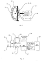
Figure 1 : Overall view of a particular embodiment of the device according to the present invention. -
Figure 2 : Block diagram of the device according to the present invention. - The device, according to the present invention, comprises a position sensor with a high resolution and high electromagnetic interference immunity Hall effect sensor to be used for controlling electric motors and mechanical shafts. Generally, said device comprises: mapping means of magnetic fields related to operational variables of an electric motor; detection means of said magnetic field; acquisition and processing means of the signals produced by said magnetic field detection means.
- With reference to
Figure 1 , we can see a possible embodiment of the device according to the present invention. Said embodiment includes the following parts: - A device for mapping magnetic fields related to operational variables of an electric motor, realised, for example, by a disk made of non-ferromagnetic material, for
example aluminium 10, provided with a certain number ofcircular sockets 11 on the outer boundary, related to the number of poles of themotor 13, the shaft angular position of which is to be measured. Said number can be chosen, for example, equal to the number of the poles of themotor 13 or equal to a multiple or a sub-multiple of said number.
In a preferred embodiment of the device according to the present invention, the said non-ferromagnetic disk shall have a diameter between 200 mm and 500 mm, in particular, a preferred embodiment of the present invention will be described in which said diameter is equal to 220 mm - A set of
magnets 12, for example circular-shaped, which fit into said sockets. In a preferred embodiment of the present invention, sixteen Nd-Fe-B circular-shaped magnets, type SC35MA80°C, having a diameter of 30 mm, a thickness of 2 mm will be used and will be placed with their geometric centers located around a circumference of 183 mm in diameter. - Two linear
Hall effect sensors magnets 12 are placed. - An interface and
acquisition card 14 which comprises means for extracting information regarding the absolute electrical angular position from the output signals of the Hall effect sensors. - According to a preferred embodiment of the present invention, said means for extracting information regarding the absolute electrical angular position from the output signals of the Hall effect sensors are shown in the block diagram in
Fig. 2 , which include the following: -
Hall effect sensors - an analog
signals processing card 22 used for: reconstructing the magnetic field value from the differential output signals ofsensors - two
analog multipliers - two
signal amplifiers - a
programmable oscillator 28; - an RTDC (Resolver To Digital Converter)
module 27, if required, namely a functional unit which is normally made with commercial components according to the methods described in the prior art and able to achieve angular information when connected to a conventional "resolver" device; - a
microprocessor acquisition card 29, if required. - The device may be completed with a self-calibration circuitry, if required, which is able, for instance, to allow proper operation even in case of parameter variations of the electronic and magnetic components caused by the ageing or altered environmental conditions in which the device operates.
- The
non-ferromagnetic disk 10 is solidly connected with the electric motor shaft, the motion of which is to be analyzed in addition to the determination of the exact angular position of the rotor. Depending on the type of motor being tested, it is possible to choose an appropriate setup of the device according to the present invention in order to allow the specific arrangement of themagnets 12 in therecesses 11 to exactly reproduce the magnetic field spectrum in order to measure the operational variables of the motor involved. As a result of such configuration, it is possible to read, at the terminals of the Hall effect sensors, for example two pairs of analog differential signals which, when appropriately processed, will result in pseudo-sinusoidal signals in quadrature between each other with the same frequency of the values of the supply current of the motor under test and from which it will be possible to extract, for example, the instantaneous electrical angular position of the rotor with a process based on the properties of elementary trigonometric functions. - The above-mentioned magnetic field mapping and detection means can be implemented within the same electric motor of which the operation parameters are being measured, without showing the problems mentioned above, and associated with the presence of a high level of electromagnetic noise generated inside the electric motor during its normal operation.
- Specifically, the method for the determination of the angular position of the motor, according to the present invention, is carried out according to the following steps:
- a) The
Hall effect sensors magnets 12 placed on the outer boundary of thealuminium disk 10, thereby generating two differential electrical signals; - b) The signals obtained at step a) are processed by the
processing card 22 in order to shape them into sinusoidal signals in quadrature between each other - c) The signals obtained at step b) will eventually be modulated in amplitude via a sinusoidal signal generated from the
programmable oscillator 28 with a suitable frequency (for example, twenty times higher, although it is also possible to employ a "zero frequency" modulating signal: in this case the output signal from the multiplier will have the same shape of the original input signal and an amplitude scaled up or down by a multiplicative constant) relative to the maximum electric frequency of the motor supply current, said maximum frequency being equal to the frequency of rotation multiplied by the number of poles of the electric machine. - d) The signals obtained at step c) are processed by a "Resolver To Digital Converter" (RTDC)
circuitry 27 in order to extract the data related to the angular position of the motor, thereby making it available for subsequent processings, if any. - The following specifies more in detail the processings carried out by the method previously described.
- Assuming θ is the instantaneous electrical angular position of the rotor to be determined; and assuming A is the amplitude and ω the angular frequency of the sinusoidal carrier used in step c). The modulated signals generated at step c) and sent to the "Resolver To Digital Converter" (RTDC) will be as follows:


- The RTDC board, already known in the prior art, is generally designed as to transform this information directly into the value of θ which represents the measurement of the required angle, output through a negative feedback system.
- Let's assume that the RTDC system starts from any arbitrary angle θ value, assuming it is φ, generically represented in digital form by a digital counter within the RTDC board;
- In step d), within the RTDC board, the two signals mentioned above are respectively multiplied by the cosine and by the sine of the angle φ, thereby obtaining the following signals:


- At the output of the multiplier of the RTDC board, an error amplifier subtracts signal x2 from signal x1, thus obtaining:


- Lastly, a negative feedback system inside the RTDC board, based on a Phase Locked Loop (PLL), quickly adjusts the value φ of the counter so as to eliminate the angular error (θ-φ).
- Therefore, the signal obtained in step d) of the method according to the present invention contains the information related to the absolute electrical angular position which is stored into the N bit counter of the RTDC board and can be output using several communication protocols, such as, for example, serial, parallel, incremental encoder emulation protocols etc.
Claims (18)
- Device for measuring operational variables of electric motors comprising mapping means of magnetic fields related to operational variables of an electric motor; detection means of said magnetic field; acquisition and professing means of the signals produced by said magnetic field detection means wherein said mapping means of the electric motor magnetic field comprise: a non-ferromagnetic disk (10) provided with a plurality of peripheral sockets (11) and solidly connected with the shaft of said electric motor; a plurality of magnets (12) set into said sockets; said detection means of the electric motor magnetic field comprise a pair of Hall effect sensors (20, 21) facing said non-ferromagnetic disk (10) on the surface of which said magnets (12) are set and adapted to generate two differential electrical signals; b) the device further comprising a processing card (22) adapted for processing the signals in order to shape them as sinusoidal signals in quadrature between each other;
- Device according to claim 1, wherein said Hall effect sensors are placed in electrical quadrature between each other.
- Device according to claim 1 or 2, wherein said Hall effect sensors are placed in such a way to produce, at the output terminals of said Hall effect sensors, two pairs of analog differential signals in quadrature between each other with the same frequency of the supply current of the motor under test.
- Device according to claim 3, wherein said Hall effect sensors are of the differential type.
- Device according to any claim from 1 to 4, wherein said mapping and detection means of the magnetic field related to operational variables of an electric motor are located within the electric motor. a programmable oscillator (28) adapted for modulating in amplitude said sinusoidal signals via a sinusoidal signal with an appropriate frequency with respect to the maximum electrical frequency of the motor supply current, said maximum frequency being equal to the frequency of rotation multiplied by the number of poles of the electric machine;
the modulated signals having a mathematical representation as Asinωt sinθ where θ is the instantaneous electrical angular position of the rotor to be determined, A is the amplitude and ω the angular frequency of the sinusoidal carrier used by said oscillator, the device further comprising a Resolver To Digital Converter (27) which, in use, multiplies said modulator signals by the cosine and by the sine of an arbitrary angle Φ, in order to obtain two signals in the form of Asinωt sinθ sinΦ and Asinωt sinθ cosΦ which are then subtracted from each other and then filtered through a negative feedback system inside said Resolver To Digital Converter circuitry in order to extract the value of θ data related to the angular position of the motor;
means for, directly using the modulated signal containing the information related to the absolute electrical angular position θ as it is for control purposes or for storing it into the N bit counter of the Resolver To Digital Converter board; and means for outputting said modulated signal using several communication protocols chosen from the group comprising serial protocols, parallel protocols, incremental encoder emulation protocols. - Device according to any claim from 1 to 5, wherein said acquisition and processing means of the signals produced by said magnetic field detection means comprise: said analog signal processing card (22); at least one signal amplifier; at least said programmable oscillator (28).
- Device according to claim 6, wherein it comprises at least one analog multiplier.
- Device according to claim 6 or 7, further comprising a microprocessor acquisition card (29).
- Device according to any claim from 6 to 8 further comprising a self-calibration circuitry.
- Device according to any of the preceeding claims, wherein the number of said preferably circular sockets (11) is related to the number of poles of said electric motor.
- Device according to claim 10, wherein the number of said preferably circular sockets (11) is equal to the number of poles of said electric motor.
- Device according to claim 11, wherein the number of said preferably circular sockets (11) is a multiple or a sub-multiple of the number of poles of said electric motor.
- Device according to any of the preceeding claims, further comprising a non-ferromagnetic disk (10) provided with a plurality of peripheral sockets (11), preferably circular, and locked onto the shaft of said electric motor; a plurality of magnets (12) set into said sockets; a pair of Hall effect sensors (20, 21) placed in such a way to induce electrical quadrature signals in the sensors and facing said non-ferromagnetic disk (10) on the surface of which said magnets (12) are set; an analog signal processing card (22); a pair of analog multipliers (23, 24); a pair of signal amplifiers (25, 26); a programmable oscillator (28); a Resolver To Digital Converter module (27); a microprocessor acquisition card (29); a self-calibration circuitry.
- Device according to claim 13, wherein said non-ferromagnetic disk (10) has a diameter between 200 and 500 mm.
- Device according to claim 14, wherein said non-ferromagnetic disk is made of aluminium.
- Device according to any claim from 13 to 15 wherein the said magnets (12) are of the Nd-Fe-B type.
- Device according to any claim from 13 to 16 wherein said magnets (12) have a diameter between 30 and 90 mm and a thickness between 1.5 and 10 mm.
- Method for measuring operational variables of electric motors, performed by a device according to any claim from 1 to 17, the method comprising the following steps:a) Detecting the magnetic field generated by the magnets (12) placed on the outer boundary of the non-ferromagnetic disk (10) via the Hall effect sensors (20, 21), generating two differential electrical signals.b) Processing the signals generated in step a) by the processing card (22) in order to shape them as sinusoidal signals in quadrature between each other.c) Modulating the signals obtained in step b) in amplitude via a sinusoidal signal generated by the programmable oscillator (28) with an appropriate frequency with respect to the maximum electrical frequency of the motor supply current, said maximum frequency being equal to the frequency of rotation multiplied by the number of poles of the electric machine.d) Processing the signals generated at step c) - which have a mathematical representation as Asinωt sinθ where θ is the instantaneous electrical angular position of the rotor to be determined, A is the amplitude and ω the angular frequency of the sinusoidal carrier used in step c) - by the Resolver To Digital Converter circuitry (27) which multiplies them by the cosine and by the sine of an arbitrary angle Φ, in order to obtain two signals in the form of Asinωt sinθ sinΦ and Asinωt sinθ cosΦ which are then subtracted from each other and then filtered through a negative feedback system inside said Resolver To Digital Converter circuitry in order to extract the value of θ data related to the angular position of the motor.e) either using the signal obtained in step d) containing the information related to the absolute electrical angular position θ as it is for control purposes or storing said signal into the N bit counter of the Resolver to Digital Converter board and optionally outputting said signal using several communication protocols chosen from the group comprising serial protocols, parallel protocols, incremental encoder emulation protocols.
Applications Claiming Priority (2)
| Application Number | Priority Date | Filing Date | Title |
|---|---|---|---|
| ITMI20041112 | 2004-06-01 | ||
| IT001112A ITMI20041112A1 (en) | 2004-06-01 | 2004-06-01 | HIGH RESOLUTION AND HIGH IMMUNITY ELECTRO-ELECTRIC NOISE POSITION SENSOR |
Publications (3)
| Publication Number | Publication Date |
|---|---|
| EP1602898A2 EP1602898A2 (en) | 2005-12-07 |
| EP1602898A3 EP1602898A3 (en) | 2006-06-07 |
| EP1602898B1 true EP1602898B1 (en) | 2010-03-10 |
Family
ID=34978943
Family Applications (1)
| Application Number | Title | Priority Date | Filing Date |
|---|---|---|---|
| EP05104696A Expired - Fee Related EP1602898B1 (en) | 2004-06-01 | 2005-05-31 | High resolution hall effect position sensor with a high immunity against electromagnetic noise |
Country Status (4)
| Country | Link |
|---|---|
| US (1) | US7414392B2 (en) |
| EP (1) | EP1602898B1 (en) |
| DE (1) | DE602005019809D1 (en) |
| IT (1) | ITMI20041112A1 (en) |
Families Citing this family (13)
| Publication number | Priority date | Publication date | Assignee | Title |
|---|---|---|---|---|
| DE102006012890A1 (en) * | 2006-03-13 | 2007-09-20 | Valeo Schalter Und Sensoren Gmbh | Switch, in particular vehicle switch, evaluation unit therefor and associated switch unit |
| TW200804714A (en) * | 2006-07-05 | 2008-01-16 | Li-Qi Chen | A lubricant gun with a counter |
| ITTO20060526A1 (en) * | 2006-07-19 | 2008-01-20 | Bitron Spa | KNOB CONTROL DEVICE, PARTICULARLY FOR MOTOR VEHICLES. |
| US7631885B2 (en) | 2007-04-16 | 2009-12-15 | Harley-Davidson Motor Company Group, LLC | Intelligent interlock for a motorcycle stand |
| US8497685B2 (en) * | 2007-05-22 | 2013-07-30 | Schlumberger Technology Corporation | Angular position sensor for a downhole tool |
| JP5172833B2 (en) * | 2007-05-30 | 2013-03-27 | 株式会社ハーモニック・ドライブ・システムズ | AC servo motor rotational position detection method and simple encoder |
| TWI420071B (en) * | 2008-06-27 | 2013-12-21 | Hon Hai Prec Ind Co Ltd | Measuring system |
| US20120235616A1 (en) * | 2011-03-17 | 2012-09-20 | Remy Technologies, L.L.C. | Position sensing system for a three (3) phase electric motor |
| CN102826166B (en) * | 2012-07-28 | 2014-03-26 | 成都宽和科技有限责任公司 | Sensor with unevenly distributed magnetic blocks in shell |
| CN105472117B (en) * | 2014-09-09 | 2019-08-30 | Abb瑞士股份有限公司 | Systems to monitor the health of motors, mobile phones, and server-based systems |
| CA2961763C (en) | 2014-09-19 | 2019-01-08 | Flow Control Llc. | Automatic fill control technique |
| WO2017037072A1 (en) * | 2015-08-31 | 2017-03-09 | bNovate Technologies SA | Rotary valve and pump system with rotary valve |
| CN111897017A (en) * | 2020-08-24 | 2020-11-06 | 国网山东省电力公司滨州市沾化区供电公司 | Buried cable path detection device |
Family Cites Families (18)
| Publication number | Priority date | Publication date | Assignee | Title |
|---|---|---|---|---|
| NL254347A (en) * | 1959-09-23 | |||
| GB1470383A (en) * | 1973-04-03 | 1977-04-14 | Lucas Electrical Ltd | Apparatus for producing signals indicating increments of angular movement of a body |
| GB1490987A (en) * | 1974-03-08 | 1977-11-09 | Westinghouse Brake & Signal | Vehicle movement control arrangements |
| US4086519A (en) | 1977-02-25 | 1978-04-25 | Electro-Craft Corporation | Hall effect shaft angle position encoder |
| US4733117A (en) * | 1987-04-27 | 1988-03-22 | The Superior Electric Company | Reluctance synchro/resolver |
| US5543672A (en) * | 1989-10-18 | 1996-08-06 | Yazaki Corporation | Rotation detecting device with magnet brake |
| US5258735A (en) * | 1991-10-28 | 1993-11-02 | Allwine Jr Elmer C | Multi-pole composite magnet used in a magnetic encoder |
| DE4445120A1 (en) * | 1993-12-22 | 1995-06-29 | Teves Gmbh Alfred | Rotary or angular movement detector |
| CA2143811A1 (en) * | 1994-03-04 | 1995-09-05 | Jeffrey L. Mccurley | Field strength position sensor with improved bearing tolerance in reduced space |
| DE19536433C2 (en) * | 1995-09-29 | 1999-04-08 | Siemens Ag | Device for contactless position detection of an object and use of the device |
| AU7313996A (en) | 1995-10-17 | 1997-05-07 | Scientific Generics Limited | Position encoder |
| SE511135C2 (en) * | 1997-04-30 | 1999-08-09 | Dresser Wayne Ab | Methods and apparatus for generating digital signal changes when determining the amount of fuel output from a fuel pump unit |
| US5982169A (en) * | 1997-09-24 | 1999-11-09 | Eastman Kodak Company | Micro-encoder with molded micro-magnet |
| JP4936299B2 (en) | 2000-08-21 | 2012-05-23 | メレクシス・テクノロジーズ・ナムローゼフェンノートシャップ | Magnetic field direction detection sensor |
| US6639399B2 (en) * | 2001-02-06 | 2003-10-28 | Delphi Technologies, Inc. | Target wheel sensor assembly for determining position and direction of motion of a rotating target wheel |
| US20030117132A1 (en) * | 2001-12-21 | 2003-06-26 | Gunnar Klinghult | Contactless sensing input device |
| JP2004117318A (en) * | 2002-09-30 | 2004-04-15 | Ntn Corp | Bearing with rotation sensor, and motor using the same |
| US7116100B1 (en) * | 2005-03-21 | 2006-10-03 | Hr Textron, Inc. | Position sensing for moveable mechanical systems and associated methods and apparatus |
-
2004
- 2004-06-01 IT IT001112A patent/ITMI20041112A1/en unknown
-
2005
- 2005-05-31 DE DE602005019809T patent/DE602005019809D1/en not_active Expired - Lifetime
- 2005-05-31 EP EP05104696A patent/EP1602898B1/en not_active Expired - Fee Related
- 2005-06-01 US US11/141,914 patent/US7414392B2/en not_active Expired - Fee Related
Also Published As
| Publication number | Publication date |
|---|---|
| EP1602898A2 (en) | 2005-12-07 |
| US7414392B2 (en) | 2008-08-19 |
| US20050264283A1 (en) | 2005-12-01 |
| ITMI20041112A1 (en) | 2004-09-01 |
| EP1602898A3 (en) | 2006-06-07 |
| DE602005019809D1 (en) | 2010-04-22 |
Similar Documents
| Publication | Publication Date | Title |
|---|---|---|
| Zheng et al. | A capacitive rotary encoder based on quadrature modulation and demodulation | |
| US6433536B1 (en) | Apparatus for measuring the position of a movable member | |
| JP5613839B2 (en) | Method and apparatus for absolute positioning of a moving object | |
| US7414392B2 (en) | High resolution hall effect sensor devices for measuring operating parameters of electric motors and methods thereof | |
| EP3640602A1 (en) | Method for detecting errors in a rotating position sensor system having sine and cosine signals | |
| EP2827106B1 (en) | Angle detection device | |
| US11984837B2 (en) | Method for determining an angular position of a rotating component, in particular of an electric motor for a clutch actuation system of a vehicle | |
| JP4142607B2 (en) | Variable reluctance resolver | |
| US10436611B2 (en) | Rotation angle measuring apparatus and measuring method | |
| KR20120088677A (en) | Method for analyzing signals from an angle sensor | |
| CN113412574B (en) | Method for determining the angle of a rotor of an electric motor, controller and vehicle | |
| EP3712632B1 (en) | Electronic circuit for measuring an angle and an intensity of an external magnetic field | |
| EP2693221A1 (en) | Magnetic Sensor Arrangement | |
| JP2016031332A (en) | Capacitance type angle detecting device | |
| US5933106A (en) | Encoder signal analysis system for high-resolution position measurement | |
| JP2839340B2 (en) | Calibration device for position signal | |
| Reddy et al. | Inverse tangent based resolver to digital converter-A software approach | |
| CN116249874A (en) | Method and device for measuring the mechanical angular position of a rotor | |
| EP1016852B1 (en) | Apparatus for measuring the position of a movable member | |
| JPH0230726Y2 (en) | ||
| CN116164630A (en) | Apparatus and method for position detection with error detection using position sensor | |
| TWI798331B (en) | Method and device for detecting position change of moving object | |
| JP3564831B2 (en) | Signal processing circuit in measuring equipment | |
| EP1916528A2 (en) | Device for sensing the angular speed and position of a rotating element | |
| KR100914521B1 (en) | Motor rotor position measurement method and system using edge magnetic flux, Hall sensor support structure for it |
Legal Events
| Date | Code | Title | Description |
|---|---|---|---|
| PUAI | Public reference made under article 153(3) epc to a published international application that has entered the european phase |
Free format text: ORIGINAL CODE: 0009012 |
|
| AK | Designated contracting states |
Kind code of ref document: A2 Designated state(s): AT BE BG CH CY CZ DE DK EE ES FI FR GB GR HU IE IS IT LI LT LU MC NL PL PT RO SE SI SK TR |
|
| AX | Request for extension of the european patent |
Extension state: AL BA HR LV MK YU |
|
| PUAL | Search report despatched |
Free format text: ORIGINAL CODE: 0009013 |
|
| AK | Designated contracting states |
Kind code of ref document: A3 Designated state(s): AT BE BG CH CY CZ DE DK EE ES FI FR GB GR HU IE IS IT LI LT LU MC NL PL PT RO SE SI SK TR |
|
| AX | Request for extension of the european patent |
Extension state: AL BA HR LV MK YU |
|
| 17P | Request for examination filed |
Effective date: 20061205 |
|
| AKX | Designation fees paid |
Designated state(s): DE FR |
|
| 17Q | First examination report despatched |
Effective date: 20070801 |
|
| RIC1 | Information provided on ipc code assigned before grant |
Ipc: G01D 5/14 20060101AFI20090722BHEP |
|
| GRAP | Despatch of communication of intention to grant a patent |
Free format text: ORIGINAL CODE: EPIDOSNIGR1 |
|
| RAP1 | Party data changed (applicant data changed or rights of an application transferred) |
Owner name: ANSALDO ENERGIA S.P.A. |
|
| GRAS | Grant fee paid |
Free format text: ORIGINAL CODE: EPIDOSNIGR3 |
|
| GRAA | (expected) grant |
Free format text: ORIGINAL CODE: 0009210 |
|
| AK | Designated contracting states |
Kind code of ref document: B1 Designated state(s): DE FR |
|
| REF | Corresponds to: |
Ref document number: 602005019809 Country of ref document: DE Date of ref document: 20100422 Kind code of ref document: P |
|
| PLBE | No opposition filed within time limit |
Free format text: ORIGINAL CODE: 0009261 |
|
| STAA | Information on the status of an ep patent application or granted ep patent |
Free format text: STATUS: NO OPPOSITION FILED WITHIN TIME LIMIT |
|
| 26N | No opposition filed |
Effective date: 20101213 |
|
| PGFP | Annual fee paid to national office [announced via postgrant information from national office to epo] |
Ref country code: DE Payment date: 20120531 Year of fee payment: 8 |
|
| PGFP | Annual fee paid to national office [announced via postgrant information from national office to epo] |
Ref country code: FR Payment date: 20120615 Year of fee payment: 8 |
|
| PG25 | Lapsed in a contracting state [announced via postgrant information from national office to epo] |
Ref country code: DE Free format text: LAPSE BECAUSE OF NON-PAYMENT OF DUE FEES Effective date: 20131203 |
|
| REG | Reference to a national code |
Ref country code: DE Ref legal event code: R119 Ref document number: 602005019809 Country of ref document: DE Effective date: 20131203 |
|
| REG | Reference to a national code |
Ref country code: FR Ref legal event code: ST Effective date: 20140131 |
|
| PG25 | Lapsed in a contracting state [announced via postgrant information from national office to epo] |
Ref country code: FR Free format text: LAPSE BECAUSE OF NON-PAYMENT OF DUE FEES Effective date: 20130531 |