EP1602868B1 - Signal actuator device for a position adjustment control - Google Patents
Signal actuator device for a position adjustment control Download PDFInfo
- Publication number
- EP1602868B1 EP1602868B1 EP05425360A EP05425360A EP1602868B1 EP 1602868 B1 EP1602868 B1 EP 1602868B1 EP 05425360 A EP05425360 A EP 05425360A EP 05425360 A EP05425360 A EP 05425360A EP 1602868 B1 EP1602868 B1 EP 1602868B1
- Authority
- EP
- European Patent Office
- Prior art keywords
- driving shaft
- previous
- cam
- shaft
- support structure
- Prior art date
- Legal status (The legal status is an assumption and is not a legal conclusion. Google has not performed a legal analysis and makes no representation as to the accuracy of the status listed.)
- Expired - Lifetime
Links
Images


Classifications
-
- F—MECHANICAL ENGINEERING; LIGHTING; HEATING; WEAPONS; BLASTING
- F16—ENGINEERING ELEMENTS AND UNITS; GENERAL MEASURES FOR PRODUCING AND MAINTAINING EFFECTIVE FUNCTIONING OF MACHINES OR INSTALLATIONS; THERMAL INSULATION IN GENERAL
- F16K—VALVES; TAPS; COCKS; ACTUATING-FLOATS; DEVICES FOR VENTING OR AERATING
- F16K37/00—Special means in or on valves or other cut-off apparatus for indicating or recording operation thereof, or for enabling an alarm to be given
- F16K37/0008—Mechanical means
-
- F—MECHANICAL ENGINEERING; LIGHTING; HEATING; WEAPONS; BLASTING
- F16—ENGINEERING ELEMENTS AND UNITS; GENERAL MEASURES FOR PRODUCING AND MAINTAINING EFFECTIVE FUNCTIONING OF MACHINES OR INSTALLATIONS; THERMAL INSULATION IN GENERAL
- F16K—VALVES; TAPS; COCKS; ACTUATING-FLOATS; DEVICES FOR VENTING OR AERATING
- F16K37/00—Special means in or on valves or other cut-off apparatus for indicating or recording operation thereof, or for enabling an alarm to be given
- F16K37/0025—Electrical or magnetic means
- F16K37/0041—Electrical or magnetic means for measuring valve parameters
-
- H—ELECTRICITY
- H01—ELECTRIC ELEMENTS
- H01H—ELECTRIC SWITCHES; RELAYS; SELECTORS; EMERGENCY PROTECTIVE DEVICES
- H01H19/00—Switches operated by an operating part which is rotatable about a longitudinal axis thereof and which is acted upon directly by a solid body external to the switch, e.g. by a hand
- H01H19/54—Switches operated by an operating part which is rotatable about a longitudinal axis thereof and which is acted upon directly by a solid body external to the switch, e.g. by a hand the operating part having at least five or an unspecified number of operative positions
- H01H19/60—Angularly-movable actuating part carrying no contacts
- H01H19/62—Contacts actuated by radial cams
- H01H19/623—Adjustable cams
Definitions
- the present invention relates to a signal actuator device for a position adjustment control.
- the described solution exhibits small overall dimensions, but the engaging limited to the toothed portion of the outer surface of the hollow shaft, by offering a resistance due to said partial toothing only, defines an upper limit to the inertial action applicable to the control cam and drive shaft coupled system. Beyond said limit, the relative position between the drive shaft and the control cams is inevitably lost.
- the object of the present invention is to provide a signal actuation device for an adjustment control such as to meet the above needs and such as to overcome at the same time the disadvantages mentioned with reference to the prior art.
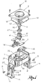
- FIG. 1 shows an axonometric exploded view of an example of embodiment of the present invention
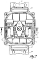
- FIG. 2 shows an overall top view of a signal actuation device for an adjustment control according to the invention
- figure 3 shows a section view along line III-III of the device of figure 2 ;
- figure 4 shows an axonometric exploded view of details of the device of figure 1 ;
- figure 5 shows an axonometric partly section view of details of the device of figure 4 .
- reference numeral 1 indicates a support structure, or body, which defines, for example, a housing advantageously shaped as a parallelepiped with for example at least one lacking surface and another surface wherein there is obtained a thorough opening 20.
- said housing exhibits two side protrusions 21 wherein there are obtained at least two cavities geometrically connectable with at least two carrying brackets 11 that engage into said side protrusions and at least one thorough sealing hole 22, preferably two holes, whose axis is arranged in a direction transversal to the direction of engagement of said brackets, said carrying brackets 11 having a height adjustment system obtained in the surface thereof consisting of thorough adjustment holes that allow the possible geometrical coupling between at least one sealing nut 8, at least one support screw 9, at least one thorough sealing hole 22 and at least one thorough adjustment hole 23.
- Said brackets 11 have a cross support surface 24 suitable for being fixed to a support surface, for example a masonry construction (not shown in the figure), for example through thorough openings.
- said support surface is favourably adjustable by engaging the brackets into one of the different directions allowed by the geometry of the coupling of said brackets 11 with said geometrically connectable cavities obtained in said side protrusions present for example on said housing 1.
- said body of device 1 there are housed two electrical devices 13 and 14, said electrical devices being firmly locked by a clamp 7, for example a stop plate that constrains them to positioning projections 25 suitable for arranging them into a predetermined position relative to further components of the device that will be described in detail hereinafter.
- a clamp 7 for example a stop plate that constrains them to positioning projections 25 suitable for arranging them into a predetermined position relative to further components of the device that will be described in detail hereinafter.
- a stem, or bottom drive shaft 4 is further inserted into said body of device 1, protruding with one end thereof from a surface of said body 1 through said thorough opening 20.
- Said stem can be connected for example by a connecting pin 26 by shape coupling with an adapted or conjugate end of an eventual transmission shaft, not shown in the figure.
- the bottom drive shaft 4 exhibits a disc-shaped surface, or flange 27, transversal to the axis of the bottom drive shaft 4 that easily rests preferably on the inner surface of the body of device 1.
- said electrical devices 13 and 14 are symmetrically arranged relative to said stem 4 inserted in the surface of housing 1.
- a housing cavity 28 ( figure 4 ) is obtained at the top end of said stem 4.
- Said bottom drive shaft 4 comprises a projection, preferably annular, forming an axial abutment surface 31 arranged, relative to said toothing 29, at the side opposed to the free end provided with said coupling housing 28.
- At least one bottom control cam 6' Geometrically coupled to said toothing there is provided, for example, at least one bottom control cam 6'.
- This is made with an annular configuration and exhibiting a central thorough hole, whose inner wall is provided with a toothing 30 or knurled, for example with a shape conjugate to that of the stem.
- the latter inner toothing 30 interacts with said outer toothing of the bottom drive shaft 4 so as to carry out a shape coupling between the bottom drive shaft 4 and the bottom control cam 6'.
- a top drive shaft 3 Inserted in axial direction into said housing cavity 28 is a top drive shaft 3, along whose outer surface there is obtained a longitudinal shaping, or groove 32, so that it forms a shape coupling with conjugate groove provided in said housing cavity 28.
- Said top drive shaft 3 is integral to said bottom drive shaft 4.
- Said removable integral connection is for example obtained by slightly conical radial projections 33 which, by coupling into said housing 28 of the bottom shaft, determine a force coupling, or are forced, into said housing 28.
- said stem 4 and said top shaft 3 when coupled, form an integral system with each other.
- an annular structure is axially inserted relative to the top shaft 3, which exhibits a toothing 34 or knurled in the outer wall, suitable for geometrically coupling in the direction of the axis of the top drive shaft with at least one annexed top control cam 6", said top control cam being made with an annular configuration and exhibiting a central thorough hole, whose inner wall is provided with a conjugate toothing 35 or knurled.
- a projection forming at least one axial abutment surface 36.
- an indicator 37 suitable for displaying the angular position of said shaft.
- the top portion of the top shaft 3 exhibits a shape useful for providing angular positioning indications to an operator, such shape being preferably assimilable to the shape of a flywheel.
- Said housing 1 exhibits at least one threaded hole along the top edge of the surface thereof. In a favourable configuration, there are provided four threaded holes.
- Housing 1 is closed at its top side preferably by a cover 2 which in a favourable configuration can be made for example of a translucent or transparent material, and can exhibit for example at least one threaded thorough hole on the surface thereof. Preferably, there are provided four threaded thorough holes.
- a gasket 12 is inserted between the contact surfaces of said housing 1 and said cover 2.
- the presence of at least one sealing screw 10 carries out the fixing of said cover 2 relative to said housing 1, coupling at least one threaded hole present on the surface of housing 1 to at least one threaded thorough hole present on the surface of cover 2.
- four sealing screws 10 can be provided, which engage said threaded holes present on the surface of housing 1 and said threaded thorough holes present on the surface of cover 2.
- said device is shown in a top view in figure 2
- figure 3 shows an embodiment in a side section view.
- the bottom drive shaft 4 transmits any twisting torque received for example from a transmission shaft coupled to said connection pin present at the bottom of stem 4, to the integrally coupled top drive shaft 3. Said twisting torque causes a rotation of stem 4 and of the top drive shaft 3 about its axis.
- said rotation about the axis of stem 4 transmitted by the top drive shaft 3 can for example be in phase.
- said stem 4 transmits said twisting torque to the bottom control cam 6' integrally coupled to stem 4 for example through the geometrical coupling of said toothing 29.
- said twisting torque transmitted to the top shaft 3 carries said top control cam 6" into rotation, favourably using the geometrical coupling between the knurled of said top control cam 6" and the toothing of said top shaft 3.
- the cams 6' and 6" are arranged as a package.
- cams 6' and 6" during the rotary motion imparted to them by the twisting torque transmitted by stem 4 and by indicator 3 integrally coupled, advantageously interact with said electrical devices.
- said electrical devices can for example be electrical or mechanical switches 13, 14.
- the embodiment as described above for example exhibits the advantage of being able to display the rotary motion of the drive shaft 3. Actually, if for example the rotary device is not engaged with a twisting torque, it is possible to check whether indicator 3 is moving or not by looking through cover 2 which in a possible embodiment is of a transparent material.
- said extraction can even be partial only, so that said top shaft 3 remains engaged with said stem 4, and the manoeuvring space required for the adjustment of a cam 6' is obtained.
- the top control cam 6" remains integrally fixed to said top shaft 3.
- the cams are arranged again in a package structure.
- cams 6' and 6" are restored.
- the embodiment illustrated by way of an example allows a package distribution of the cams, for example moving the first cam 6' in contact with the second cam 6", an arrangement not known in the prior art that produces very small overall dimensions thanks to the absence of further bodies arranged between the surfaces of the cams that reciprocally face each other. Moreover, in this embodiment, it is not necessary to provide for disengagement spaces, useful in the art for optional adjustments of the relative angular position of cams and shaft, overlying and/or underlying the cams for possible axial and rotating reciprocal movements of the cams themselves.
Landscapes
- Engineering & Computer Science (AREA)
- General Engineering & Computer Science (AREA)
- Mechanical Engineering (AREA)
- Transmission Devices (AREA)
- Lighting Device Outwards From Vehicle And Optical Signal (AREA)
- Fluid-Damping Devices (AREA)
- Seats For Vehicles (AREA)
- Mobile Radio Communication Systems (AREA)
- Radar Systems Or Details Thereof (AREA)
- Selective Calling Equipment (AREA)
- Control Of Position Or Direction (AREA)
Abstract
Description
- The present invention relates to a signal actuator device for a position adjustment control.
- Devices of this type are known, provided with drive shafts having the possibility of changings the relative position of control cams relative to said shafts.
- Drive shafts of this type are know for example in
FR-A-2 474 754 EP-A-0 437 664 . - Signal actuators of this type are already known in the prior art, for example from
US 5,305,781 . In this know device, in order to locally adjust the signal actuator it is necessary to provide for a possibility of positioning the control cams into multiple angular positions relative to the drive shaft; it is therefore known, for example, to provide a fastening by shape-coupling of the control cams through a toothing of the components mentioned hereinabove. In this case, to make any adjustments it is necessary to axially move at least one control cam provided with an inner toothing beyond the outer toothing engagement zone of the drive shaft, in order to carry out the desired adjustment of an intermediate zone of the drive shaft not provided with toothing. Afterwards it is necessary to rearrange the control cam to the original axial position for carrying out a new shape coupling again. It is apparent that such an adjustment is excessively expensive and not practical, in particular in the case a plurality of control cams is arranged axially superimposed on one another and it is disadvantageously necessary to move at least the control cam to the bottom end of the drive shaft. In such a situation, it may understandably occur that the top control cam originally located in the correct angular position relative to the drive shaft, after the adjustment operation that has caused its separation and the subsequent reintroduction, is in an incorrect angular position relative to the drive shaft and that this requires a further adjustment. Moreover, as disclosed for example inUS 5,223,822 , it is known to provide the control cams with a front toothing that interacts respectively with a front toothing on a seat of the drive shaft. With the aid of a spring acting in axial direction, the two correspondingly coupled front toothing sets are pressed against one another so as to form a torsion-resistant connection between the control cam and the drive shaft. In this way, in case of adjustment, by acting against the spring force it is possible to temporarily disconnect the control cam from the fixed toothing on the shaft and after the transfer to the desired angular position, replace the cam coupled to the fixed toothing of the drive shaft, without the action of a further external force. This allows firmly coupling the control cam to the drive shaft, allowing operating conditions with high angular accelerations while ensuring that the angular position of the control cam relative to the drive shaft is maintained. It is understood, however, that the adjustment principle mentioned above is not advantageous as it requires a greater construction complexity and implies an increase of the overall dimensions of the device, as spaces overlying and underlying the control cams are to be provided for the disengagement and the optional rotation of the control cams, with clear disadvantages. - It is also known in the art, for example in
EP-A-0921338 , a coupling system between at least two stacked control cams and an hollow drive shaft provided with a limited toothed portion of the outer surface of the hollow drive shaft for the remainder free from toothing that has an elastic flexibility degree in radial direction. Such drive shaft is connectable through the above partial outer toothing to the stacked control cams; in this case, the adjustment is entrusted to the elastic flexibility of the toothed portion of the outer surface of the drive shaft. In this way, in case of adjustment, by acting with an appropriate tool against the elastic force of said toothed portion, it is possible to arrange the control cams in the desired angular position. Actually, the described solution exhibits small overall dimensions, but the engaging limited to the toothed portion of the outer surface of the hollow shaft, by offering a resistance due to said partial toothing only, defines an upper limit to the inertial action applicable to the control cam and drive shaft coupled system. Beyond said limit, the relative position between the drive shaft and the control cams is inevitably lost. - There is therefore the need of providing a signal actuation device for an adjustment control which should be useful also in operating conditions with high angular accelerations, ensuring a firm fixing between control cams and drive shaft; moreover, said device must have small overall dimensions.
- The object of the present invention is to provide a signal actuation device for an adjustment control such as to meet the above needs and such as to overcome at the same time the disadvantages mentioned with reference to the prior art.
- The features and advantages of the present invention will appear more clearly from the following description, made by way of an indicative non-limiting example with reference to the annexed drawings, wherein:
- -
figure 1 shows an axonometric exploded view of an example of embodiment of the present invention; - -
figure 2 shows an overall top view of a signal actuation device for an adjustment control according to the invention; - -
figure 3 shows a section view along line III-III of the device offigure 2 ; - -
figure 4 shows an axonometric exploded view of details of the device offigure 1 ; - -
figure 5 shows an axonometric partly section view of details of the device offigure 4 . - With reference to the annexed figures, and as regards a possible embodiment,
reference numeral 1 indicates a support structure, or body, which defines, for example, a housing advantageously shaped as a parallelepiped with for example at least one lacking surface and another surface wherein there is obtained athorough opening 20. - In one embodiment thereof proposed as non-limiting example, said housing exhibits two
side protrusions 21 wherein there are obtained at least two cavities geometrically connectable with at least two carryingbrackets 11 that engage into said side protrusions and at least onethorough sealing hole 22, preferably two holes, whose axis is arranged in a direction transversal to the direction of engagement of said brackets, said carryingbrackets 11 having a height adjustment system obtained in the surface thereof consisting of thorough adjustment holes that allow the possible geometrical coupling between at least one sealingnut 8, at least onesupport screw 9, at least onethorough sealing hole 22 and at least onethorough adjustment hole 23. Saidbrackets 11 have across support surface 24 suitable for being fixed to a support surface, for example a masonry construction (not shown in the figure), for example through thorough openings. Moreover, said support surface is favourably adjustable by engaging the brackets into one of the different directions allowed by the geometry of the coupling of saidbrackets 11 with said geometrically connectable cavities obtained in said side protrusions present for example on saidhousing 1. - In said body of
device 1 there are housed twoelectrical devices clamp 7, for example a stop plate that constrains them to positioningprojections 25 suitable for arranging them into a predetermined position relative to further components of the device that will be described in detail hereinafter. - A stem, or
bottom drive shaft 4 is further inserted into said body ofdevice 1, protruding with one end thereof from a surface of saidbody 1 through saidthorough opening 20. Said stem can be connected for example by a connectingpin 26 by shape coupling with an adapted or conjugate end of an eventual transmission shaft, not shown in the figure. - The
bottom drive shaft 4 exhibits a disc-shaped surface, orflange 27, transversal to the axis of thebottom drive shaft 4 that easily rests preferably on the inner surface of the body ofdevice 1. - In a possible variant of the present invention, said
electrical devices stem 4 inserted in the surface ofhousing 1. - A housing cavity 28 (
figure 4 ) is obtained at the top end of saidstem 4. - Along the outer perimeter of said
stem 4, a relief toothing 29, also called knurled, is obtained. - Said
bottom drive shaft 4 comprises a projection, preferably annular, forming anaxial abutment surface 31 arranged, relative to said toothing 29, at the side opposed to the free end provided with saidcoupling housing 28. - Geometrically coupled to said toothing there is provided, for example, at least one bottom control cam 6'. This is made with an annular configuration and exhibiting a central thorough hole, whose inner wall is provided with a toothing 30 or knurled, for example with a shape conjugate to that of the stem. The latter
inner toothing 30 interacts with said outer toothing of thebottom drive shaft 4 so as to carry out a shape coupling between thebottom drive shaft 4 and the bottom control cam 6'. - Inserted in axial direction into said
housing cavity 28 is atop drive shaft 3, along whose outer surface there is obtained a longitudinal shaping, orgroove 32, so that it forms a shape coupling with conjugate groove provided in saidhousing cavity 28. - Said
top drive shaft 3 is integral to saidbottom drive shaft 4. Said removable integral connection is for example obtained by slightly conicalradial projections 33 which, by coupling into saidhousing 28 of the bottom shaft, determine a force coupling, or are forced, into saidhousing 28. - Favourably, said stem 4 and said
top shaft 3 when coupled, form an integral system with each other. - Preferably, an annular structure is axially inserted relative to the
top shaft 3, which exhibits atoothing 34 or knurled in the outer wall, suitable for geometrically coupling in the direction of the axis of the top drive shaft with at least one annexedtop control cam 6", said top control cam being made with an annular configuration and exhibiting a central thorough hole, whose inner wall is provided with aconjugate toothing 35 or knurled. At the side opposed to the free and coupling end of saidtop shaft 3 there is provided a projection forming at least oneaxial abutment surface 36. - On top of said top shaft there is associated an
indicator 37 suitable for displaying the angular position of said shaft. - According to an embodiment, the top portion of the
top shaft 3 exhibits a shape useful for providing angular positioning indications to an operator, such shape being preferably assimilable to the shape of a flywheel. - Said
housing 1 exhibits at least one threaded hole along the top edge of the surface thereof. In a favourable configuration, there are provided four threaded holes. -
Housing 1 is closed at its top side preferably by acover 2 which in a favourable configuration can be made for example of a translucent or transparent material, and can exhibit for example at least one threaded thorough hole on the surface thereof. Preferably, there are provided four threaded thorough holes. - In an optional embodiment of the present invention, a
gasket 12 is inserted between the contact surfaces of saidhousing 1 and saidcover 2. The presence of at least one sealingscrew 10 carries out the fixing of saidcover 2 relative to saidhousing 1, coupling at least one threaded hole present on the surface ofhousing 1 to at least one threaded thorough hole present on the surface ofcover 2. In a further configuration of the invention, foursealing screws 10 can be provided, which engage said threaded holes present on the surface ofhousing 1 and said threaded thorough holes present on the surface ofcover 2. - In a preferred embodiment, said device is shown in a top view in
figure 2 , whereasfigure 3 shows an embodiment in a side section view. As it can be understood, thebottom drive shaft 4 transmits any twisting torque received for example from a transmission shaft coupled to said connection pin present at the bottom ofstem 4, to the integrally coupledtop drive shaft 3. Said twisting torque causes a rotation ofstem 4 and of thetop drive shaft 3 about its axis. - Favourably, said rotation about the axis of
stem 4 transmitted by thetop drive shaft 3 can for example be in phase. - Moreover, in a further embodiment, said
stem 4 transmits said twisting torque to the bottom control cam 6' integrally coupled to stem 4 for example through the geometrical coupling of said toothing 29. Advantageously, said twisting torque transmitted to thetop shaft 3 carries saidtop control cam 6" into rotation, favourably using the geometrical coupling between the knurled of saidtop control cam 6" and the toothing of saidtop shaft 3. - The
cams 6' and 6" are arranged as a package. - Moreover, said
cams 6' and 6" during the rotary motion imparted to them by the twisting torque transmitted bystem 4 and byindicator 3 integrally coupled, advantageously interact with said electrical devices. - In a further embodiment said electrical devices can for example be electrical or
mechanical switches - The embodiment as described above for example exhibits the advantage of being able to display the rotary motion of the
drive shaft 3. Actually, if for example the rotary device is not engaged with a twisting torque, it is possible to check whetherindicator 3 is moving or not by looking throughcover 2 which in a possible embodiment is of a transparent material. - Moreover, by removing said sealing screws from
cover 2 it is possible to remove saidcover 2 and eventually physically access insidehousing 1. If an easy adjustment of the relative angular position of at least one cam 6' relative to stem 4 is to be carried out, oncecover 2 has been lifted as said it is possible to remove thetop shaft 3 with an axial movement tending to release the geometrical coupling between saidcavity 28 in the top portion ofstem 4 and said shaping 32 obtained in the bottom portion of thetop shaft 3. - In a favourable embodiment, said extraction can even be partial only, so that said
top shaft 3 remains engaged with saidstem 4, and the manoeuvring space required for the adjustment of a cam 6' is obtained. By operating in this way, advantageously thetop control cam 6" remains integrally fixed to saidtop shaft 3. - At this point it is possible to carry out the desired adjustment by disconnecting at least one cam 6' from the
bottom control shaft 4. Once the disconnection has been carried out, it is possible to axially replace a cam 6' in the desired angular position relative tostem 4. Thetop shaft 3 is then axially replaced intostem 4 in the same position it had before the adjustment operation. In this way and thanks to the integral coupling betweencam 6" and thetop shaft 3, the angular calibration ofcam 6" relative to thetop shaft 3 has advantageously been kept constant. - Since said
indicator 3 is integrally coupled in its operating position to stem 4, also the angular position ofcam 6" relative to saidstem 4 is kept unchanged. - The cams are arranged again in a package structure.
- Moreover, if the position of at least one
cam 6" relative to thetop driving shaft 3 is to be adjusted, it is advantageously possible to removecover 2 as described and axially extract saidtop shaft 3 connected to stem 4. At this point with an axial movement it is possible to extract acam 6" from its original seat and reconnect it to thetop shaft 3 with similar axial movement, after rotating it to the desired angular position. - At this point it is possible to reassemble the integral system between
stem 4 andtop shaft 3 favouring their shape coupling for example with axial movement of thetop shaft 3 towardsstem 4. - Advantageously also the desired package arrangement of
cams 6' and 6" is restored. - It is now clear that the described example of a possible embodiment of the invention certainly gives the advantage that it is possible to connect at least one bottom control cam 6' to a
stem 4, using a shape coupling due to a toothing distributed along the entire outer perimeter of the stem top portion and the toothing present on the entire inner wall of cam 6'. - Moreover, it is favourably possible to geometrically couple a
top control cam 6" through said toothing present on the entire inner wall ofcam 6" to the toothing present along the entire perimeter of said annular structure axially inserted along thetop shaft 3, annular structure advantageously obtained integrally with said top shaft. In this way, given the stability of the geometrical connection betweenstem 4 and thetop shaft 3 and the presence of a resistant toothing on the entire round angle of the interaction surface between cam 6' andstem 4 andcam 6" andtop shaft 3, it is possible to structure a rotating control device that can be subject to twisting torques, the strength of which is not limited by the presence of resistance surfaces only partly toothed. In this way it is possible to work even at high angular accelerations, without undergoing disadvantageous disconnections ofcams 6' and 6" from their resistant seats. - The embodiment illustrated by way of an example, moreover, allows a package distribution of the cams, for example moving the first cam 6' in contact with the
second cam 6", an arrangement not known in the prior art that produces very small overall dimensions thanks to the absence of further bodies arranged between the surfaces of the cams that reciprocally face each other. Moreover, in this embodiment, it is not necessary to provide for disengagement spaces, useful in the art for optional adjustments of the relative angular position of cams and shaft, overlying and/or underlying the cams for possible axial and rotating reciprocal movements of the cams themselves.
Claims (29)
- Signal actuator device for a position adjustment control, comprising:- a support structure (1) suitable for being connected to a position adjustment control, said support structure comprising a seat;- a bottom driving shaft (4) having a coupling end for a top driving shaft (3), said bottom driving shaft (4) being turnable seated in said seat of the support structure, so as to couple to a control shaft;- first torsional coupling means (29), integral with said bottom driving shaft (4) and fully extending around said shaft;- at least one first control cam (6') torsionally coupled to said first torsional coupling means (29) in a selective manner for adjusting the angular position relative to said bottom driving shaft;- said at least one first cam (6') being suitable for actuating, during its rotation, an electrical device (13, 14) supported by said support structure (1);- said top driving shaft (3) having a coupling end torsionally coupled to said bottom driving shaft (4) in a selectively removable manner;- second torsional coupling means (34), integral with said top driving shaft and fully extending around said shaft;- at least one second control cam (6") torsionally coupled to said second torsional coupling means (34) in a selective manner for adjusting the angular position relative to said top removable driving shaft;- said at least second cam (6") being suitable for actuating, during its rotation, an electrical device (13, 14) supported by said support structure (1)wherein- each of said driving shafts (3, 4) comprises at least one radial projection forming an abutment surface (31, 36) for said control cam (6', 6''),- each of said abutment surface (31, 36) comprises an abutment surface for axial abutment of the cam, said abutment surface being at a side opposed to the free ends of said shafts (3,4),- said driving shafts (3, 4) with abutment surfaces (31, 36) thereof, when associated to one another, keep said cams (6', 6") axially constrained,characterized in that- said at least one first cam (6') and said at least one second cam (6") contact each other in order to allow a package distribution of the cams (6', 6'').
- Device according to claim 1, wherein said top driving shaft (3) is selectively separable from said bottom driving shaft (4), keeping the at least one second cam (6'') associated thereto.
- Device according to any one of the previous claims, wherein said torsional coupling means (29, 34) selectively associated to one cam (6', 6'') comprise a selectively removable geometrical coupling.
- Device according to the previous claim, wherein said coupling means comprise a toothing (29, 34) connectable to a complementary toothing (30, 35) provided into said cam (6', 6'').
- Device according to the previous claim, wherein said toothing (29, 34) is a straight toothing and suitable for engaging and disengaging with a complementary straight toothing (30, 35) provided into said cam (6', 6'') according to a direction parallel to the axis of rotation of said driving shaft (3, 4).
- Device according to any one of claims 4 to 5, wherein said toothing (29, 30, 34, 35) comprises a constant step.
- Device according to any one of the previous claims, wherein each cam (6', 6'') cooperates with a respective electrical device (13, 14).
- Device according to any one of the previous claims, wherein each cam (6', 6'') cooperates with a single electrical device (13, 14).
- Device according to any one of the previous claims, wherein each cam (6', 6'') actuates an electrical switch (13, 14).
- Device according to any one of the previous claims, wherein each cam (6', 6'') actuates a mechanical switch.
- Device according to any one of the previous claims, wherein said support structure (1) comprises a housing suitable for containing said electrical device and, at least partly, the top and bottom driving shafts (3, 4).
- Device according to the previous claim, wherein said housing is a housing sealed against liquid or vapour or gas infiltrations.
- Device according to any one of the previous claims, wherein said top driving shaft (3) is geometrically coupled to the bottom driving shaft (4).
- Device according to any one of the previous claims, wherein at least one portion of said top driving shaft (3) suitable for cooperating with the bottom driving shaft (4) comprises a grooved profile (32).
- Device according to any one of the previous claims, wherein at least one portion of said top driving shaft (3) suitable for cooperating with the bottom driving shaft (4) comprises a projection (32) with variable radial dimension and suitable for a force coupling with a respective portion of a seat (28) provided in the bottom driving shaft (4).
- Device according to any one of the previous claims, wherein the bottom driving shaft (4) comprises a seat (28) suitable for the connection with the top driving shaft (3).
- Device according to any one of the previous claims, wherein the bottom driving shaft (4) comprises in a seat (28) a grooved profile suitable for associating to a corresponding complementary profile (32) provided in the top driving shaft (3).
- Device according to any one of the previous claims, wherein the bottom driving shaft (4) comprises a groove suitable for associating to a flange provided in stop means suitable for keeping the driving shaft in an operating position freely turnable constrained to the support structure (1).
- Device according to the previous claim, wherein said stop means are removable.
- Device according to any one of the previous claims, wherein said bottom driving shaft (4) comprises an abutment flange (27) against said support surface.
- Device according to any one of the previous claims, wherein said bottom driving shaft (4) is associated to a sealing gasket cooperating with the seat (20) of the support structure (1) suitable for seating the bottom driving shaft (4).
- Device according to any one of the previous claims, wherein there is comprised an indicator (37) suitable for indicating the angular position of the driving shaft.
- Device according to the previous claim, wherein said indicator (37) is in one piece with the top driving shaft.
- Device according to any one of the previous claims, wherein said support structure (1) supports the electrical device or devices at a distance from the driving shaft suitable for cooperating with the control cams (6', 6'') during the rotation of said driving shaft.
- Device according to the previous claim, wherein said devices and the driving shaft are kept into position by a stop plate.
- Device according to the previous claim, wherein said stop plate is constrained by riveted pins.
- Device according to claim 25, wherein said stop plate is constrained by screws.
- Method for adjustment of at least one control cam (6', 6'') having the following steps:- providing a signal actuator device according to any one of the previous claims,- extracting partially the top driving shaft (3) from the bottom driving shaft (4) in order to leave said top driving shaft (3) torsionally coupled with said bottom driving shaft (4) and leaving a manoeuvring space required for adjustment of said cam (6', 6''),- disconnecting said at least one cam (6', 6'') from the relative shaft (3, 4),- place said cam (6', 6'') in a desired angular position relative to the shaft (3, 4),- replace the top driving shaft (3) into the bottom driving shaft (4) leaving the top driving shaft (3) in the same angular position it had before the adjustment operation.
- Device according to any one of claims from 1 to 27, wherein all the control cams (6', 6'') coupled to said bottom driving shaft (4) and top driving shaft (3) are coupled in a separable manner for adjusting the angular position relative to said driving shafts (3, 4).
Applications Claiming Priority (2)
| Application Number | Priority Date | Filing Date | Title |
|---|---|---|---|
| ITMI20041099 | 2004-05-31 | ||
| IT001099A ITMI20041099A1 (en) | 2004-05-31 | 2004-05-31 | SIGNAL ACTUATOR DEVICE FOR A POSITION ADJUSTMENT DRIVE |
Publications (2)
| Publication Number | Publication Date |
|---|---|
| EP1602868A1 EP1602868A1 (en) | 2005-12-07 |
| EP1602868B1 true EP1602868B1 (en) | 2009-07-01 |
Family
ID=34943207
Family Applications (1)
| Application Number | Title | Priority Date | Filing Date |
|---|---|---|---|
| EP05425360A Expired - Lifetime EP1602868B1 (en) | 2004-05-31 | 2005-05-23 | Signal actuator device for a position adjustment control |
Country Status (5)
| Country | Link |
|---|---|
| US (1) | US7268307B2 (en) |
| EP (1) | EP1602868B1 (en) |
| AT (1) | ATE435392T1 (en) |
| DE (1) | DE602005015162D1 (en) |
| IT (1) | ITMI20041099A1 (en) |
Families Citing this family (5)
| Publication number | Priority date | Publication date | Assignee | Title |
|---|---|---|---|---|
| ITBS20070124A1 (en) * | 2007-08-10 | 2009-02-11 | Soldo S R L Socio Unico | SIGNAL ACTUATOR DEVICE FOR SWITCHES AND ITS CONSTRUCTION METHOD |
| ES2617257T3 (en) * | 2011-09-20 | 2017-06-16 | Soldo S.R.L. Socio Unico | Switching box |
| US20130143659A1 (en) * | 2011-12-02 | 2013-06-06 | Kyoraku Industrial Co., Ltd. | Entertainment button device and game machine |
| ITBS20130139A1 (en) | 2013-10-07 | 2015-04-08 | Soldo S R L Socio Unico | EXPLOSION-PROOF ROTARY SWITCH, EQUIPPED WITH VISUAL REPORTING MEANS AND MEANS OF CONTROL |
| US12154733B2 (en) * | 2021-09-30 | 2024-11-26 | General Equipment And Manufacturing Company, Inc. | Transmission assembly for switchbox |
Family Cites Families (14)
| Publication number | Priority date | Publication date | Assignee | Title |
|---|---|---|---|---|
| US4214133A (en) * | 1977-12-22 | 1980-07-22 | Rose John F | Rotary shaft position switch |
| DE3003271A1 (en) * | 1980-01-28 | 1981-07-30 | Conectron KG Elektro-Kleinmotoren und -Aggregatebau GmbH & Co., 1000 Berlin | MULTIPLE CAM SWITCH |
| US4939320A (en) * | 1988-03-01 | 1990-07-03 | Graulty Mark T | Self-setting switch-actuating assembly and method |
| US4962290A (en) * | 1989-11-13 | 1990-10-09 | Stonel Corporation | Shaft position indicating and display means with adjustable mounting adapter |
| IT1238321B (en) * | 1990-01-19 | 1993-07-12 | Bremas Spa | MODULAR CAMSHAFT WITH REMOVABLE CAMS IN PARTICULAR FOR ELECTRIC OR SIMILAR SWITCHES AND SWITCHES |
| DE4113332C1 (en) * | 1991-04-24 | 1992-10-08 | Maschinenfabrik Reinhausen Gmbh, 8400 Regensburg, De | |
| US5305781A (en) * | 1992-03-20 | 1994-04-26 | Bray International, Inc. | Valve positioning monitoring apparatus |
| US5223822A (en) * | 1992-04-24 | 1993-06-29 | Stonel Corporation | Valve position indicator |
| US6003837A (en) * | 1996-02-20 | 1999-12-21 | Bray International, Inc. | Valve actuator |
| DE19705576C2 (en) * | 1997-02-14 | 1999-01-07 | Reinhausen Maschf Scheubeck | Position reporting arrangement |
| DE19712153C2 (en) * | 1997-03-22 | 2000-12-14 | Asg Luftfahrttechnik Und Senso | Actuator |
| DE19754271C1 (en) * | 1997-12-06 | 1999-07-08 | Armatic Ges Fuer Automatische | Signal generator for an actuator |
| US6188030B1 (en) * | 1998-10-02 | 2001-02-13 | France/Scott Fetzer Company | Adjustment apparatus for a cam |
| US7156121B2 (en) * | 2003-12-11 | 2007-01-02 | Cox Christopher L | Valve position monitor and method of use |
-
2004
- 2004-05-31 IT IT001099A patent/ITMI20041099A1/en unknown
-
2005
- 2005-05-23 AT AT05425360T patent/ATE435392T1/en not_active IP Right Cessation
- 2005-05-23 EP EP05425360A patent/EP1602868B1/en not_active Expired - Lifetime
- 2005-05-23 DE DE602005015162T patent/DE602005015162D1/en not_active Expired - Lifetime
- 2005-05-31 US US11/140,603 patent/US7268307B2/en not_active Expired - Lifetime
Also Published As
| Publication number | Publication date |
|---|---|
| DE602005015162D1 (en) | 2009-08-13 |
| US7268307B2 (en) | 2007-09-11 |
| ATE435392T1 (en) | 2009-07-15 |
| ITMI20041099A1 (en) | 2004-08-31 |
| US20050264106A1 (en) | 2005-12-01 |
| EP1602868A1 (en) | 2005-12-07 |
Similar Documents
| Publication | Publication Date | Title |
|---|---|---|
| US8257446B2 (en) | Clutch module for prosthesis | |
| US7268307B2 (en) | Signal actuator device for a position adjustment control | |
| EP2625066B1 (en) | Adjustment mechanism | |
| US8051967B2 (en) | Step-by-step mechanism, in particular for a seat adjustment | |
| EP2304752B1 (en) | Controller unit for switching device | |
| US7796374B2 (en) | Power switchgear | |
| US7007357B2 (en) | Removal and installation device for external and internal snap rings | |
| US12560184B2 (en) | Pivot actuator | |
| CN101338796B (en) | Stop | |
| KR102741502B1 (en) | Seat height adjustment actuator | |
| AU2019203318B2 (en) | Food preparation appliance with detachable tool | |
| CN102233895B (en) | For being integrated in the holder of the holding device in the adjustable steering column of self-propelled vehicle | |
| AU2143099A (en) | Cam and cam followers for engines | |
| HU177206B (en) | Clutch with two friction disc | |
| US7878465B2 (en) | Tripod head | |
| CN102619967A (en) | Operation device of shift mechanism in manual transmission | |
| US20050241422A1 (en) | Gearshift device | |
| US6548774B1 (en) | Device for switching an electric connection, especially in a hinge switch | |
| JP2002266903A (en) | Two-way clutch and seat lifter using the same | |
| JP2020535075A (en) | Actuator device for hydraulically actuated systems of motorcycle brakes or clutches with independent adjustment of actuating lever distance and pitch | |
| KR200256588Y1 (en) | Actuator switching device for valve operating | |
| KR100870439B1 (en) | Actuator with non-penetrating waterproof switch | |
| JP6497794B1 (en) | Tilt mechanism and cooking pot equipped with the same | |
| US8047351B2 (en) | Clutch adjustment mechanism | |
| EP1916433B1 (en) | Friction Clutch and Sunblind Drive |
Legal Events
| Date | Code | Title | Description |
|---|---|---|---|
| PUAI | Public reference made under article 153(3) epc to a published international application that has entered the european phase |
Free format text: ORIGINAL CODE: 0009012 |
|
| AK | Designated contracting states |
Kind code of ref document: A1 Designated state(s): AT BE BG CH CY CZ DE DK EE ES FI FR GB GR HU IE IS IT LI LT LU MC NL PL PT RO SE SI SK TR |
|
| AX | Request for extension of the european patent |
Extension state: AL BA HR LV MK YU |
|
| 17P | Request for examination filed |
Effective date: 20060411 |
|
| AKX | Designation fees paid |
Designated state(s): AT BE BG CH CY CZ DE DK EE ES FI FR GB GR HU IE IS IT LI LT LU MC NL PL PT RO SE SI SK TR |
|
| GRAP | Despatch of communication of intention to grant a patent |
Free format text: ORIGINAL CODE: EPIDOSNIGR1 |
|
| GRAS | Grant fee paid |
Free format text: ORIGINAL CODE: EPIDOSNIGR3 |
|
| GRAA | (expected) grant |
Free format text: ORIGINAL CODE: 0009210 |
|
| AK | Designated contracting states |
Kind code of ref document: B1 Designated state(s): AT BE BG CH CY CZ DE DK EE ES FI FR GB GR HU IE IS IT LI LT LU MC NL PL PT RO SE SI SK TR |
|
| REG | Reference to a national code |
Ref country code: GB Ref legal event code: FG4D |
|
| REG | Reference to a national code |
Ref country code: CH Ref legal event code: NV Representative=s name: JACOBACCI & PARTNERS S.P.A. Ref country code: CH Ref legal event code: EP |
|
| REG | Reference to a national code |
Ref country code: IE Ref legal event code: FG4D |
|
| REF | Corresponds to: |
Ref document number: 602005015162 Country of ref document: DE Date of ref document: 20090813 Kind code of ref document: P |
|
| PG25 | Lapsed in a contracting state [announced via postgrant information from national office to epo] |
Ref country code: SI Free format text: LAPSE BECAUSE OF FAILURE TO SUBMIT A TRANSLATION OF THE DESCRIPTION OR TO PAY THE FEE WITHIN THE PRESCRIBED TIME-LIMIT Effective date: 20090701 |
|
| NLV1 | Nl: lapsed or annulled due to failure to fulfill the requirements of art. 29p and 29m of the patents act | ||
| PG25 | Lapsed in a contracting state [announced via postgrant information from national office to epo] |
Ref country code: LT Free format text: LAPSE BECAUSE OF FAILURE TO SUBMIT A TRANSLATION OF THE DESCRIPTION OR TO PAY THE FEE WITHIN THE PRESCRIBED TIME-LIMIT Effective date: 20090701 Ref country code: FI Free format text: LAPSE BECAUSE OF FAILURE TO SUBMIT A TRANSLATION OF THE DESCRIPTION OR TO PAY THE FEE WITHIN THE PRESCRIBED TIME-LIMIT Effective date: 20090701 Ref country code: IS Free format text: LAPSE BECAUSE OF FAILURE TO SUBMIT A TRANSLATION OF THE DESCRIPTION OR TO PAY THE FEE WITHIN THE PRESCRIBED TIME-LIMIT Effective date: 20091101 Ref country code: AT Free format text: LAPSE BECAUSE OF FAILURE TO SUBMIT A TRANSLATION OF THE DESCRIPTION OR TO PAY THE FEE WITHIN THE PRESCRIBED TIME-LIMIT Effective date: 20090701 Ref country code: EE Free format text: LAPSE BECAUSE OF FAILURE TO SUBMIT A TRANSLATION OF THE DESCRIPTION OR TO PAY THE FEE WITHIN THE PRESCRIBED TIME-LIMIT Effective date: 20090701 Ref country code: ES Free format text: LAPSE BECAUSE OF FAILURE TO SUBMIT A TRANSLATION OF THE DESCRIPTION OR TO PAY THE FEE WITHIN THE PRESCRIBED TIME-LIMIT Effective date: 20091012 Ref country code: SE Free format text: LAPSE BECAUSE OF FAILURE TO SUBMIT A TRANSLATION OF THE DESCRIPTION OR TO PAY THE FEE WITHIN THE PRESCRIBED TIME-LIMIT Effective date: 20090701 |
|
| PG25 | Lapsed in a contracting state [announced via postgrant information from national office to epo] |
Ref country code: NL Free format text: LAPSE BECAUSE OF FAILURE TO SUBMIT A TRANSLATION OF THE DESCRIPTION OR TO PAY THE FEE WITHIN THE PRESCRIBED TIME-LIMIT Effective date: 20090701 Ref country code: PL Free format text: LAPSE BECAUSE OF FAILURE TO SUBMIT A TRANSLATION OF THE DESCRIPTION OR TO PAY THE FEE WITHIN THE PRESCRIBED TIME-LIMIT Effective date: 20090701 |
|
| PG25 | Lapsed in a contracting state [announced via postgrant information from national office to epo] |
Ref country code: BG Free format text: LAPSE BECAUSE OF FAILURE TO SUBMIT A TRANSLATION OF THE DESCRIPTION OR TO PAY THE FEE WITHIN THE PRESCRIBED TIME-LIMIT Effective date: 20091001 Ref country code: PT Free format text: LAPSE BECAUSE OF FAILURE TO SUBMIT A TRANSLATION OF THE DESCRIPTION OR TO PAY THE FEE WITHIN THE PRESCRIBED TIME-LIMIT Effective date: 20091102 |
|
| PG25 | Lapsed in a contracting state [announced via postgrant information from national office to epo] |
Ref country code: CZ Free format text: LAPSE BECAUSE OF FAILURE TO SUBMIT A TRANSLATION OF THE DESCRIPTION OR TO PAY THE FEE WITHIN THE PRESCRIBED TIME-LIMIT Effective date: 20090701 Ref country code: DK Free format text: LAPSE BECAUSE OF FAILURE TO SUBMIT A TRANSLATION OF THE DESCRIPTION OR TO PAY THE FEE WITHIN THE PRESCRIBED TIME-LIMIT Effective date: 20090701 Ref country code: RO Free format text: LAPSE BECAUSE OF FAILURE TO SUBMIT A TRANSLATION OF THE DESCRIPTION OR TO PAY THE FEE WITHIN THE PRESCRIBED TIME-LIMIT Effective date: 20090701 |
|
| PLBE | No opposition filed within time limit |
Free format text: ORIGINAL CODE: 0009261 |
|
| STAA | Information on the status of an ep patent application or granted ep patent |
Free format text: STATUS: NO OPPOSITION FILED WITHIN TIME LIMIT |
|
| PG25 | Lapsed in a contracting state [announced via postgrant information from national office to epo] |
Ref country code: BE Free format text: LAPSE BECAUSE OF FAILURE TO SUBMIT A TRANSLATION OF THE DESCRIPTION OR TO PAY THE FEE WITHIN THE PRESCRIBED TIME-LIMIT Effective date: 20090701 Ref country code: SK Free format text: LAPSE BECAUSE OF FAILURE TO SUBMIT A TRANSLATION OF THE DESCRIPTION OR TO PAY THE FEE WITHIN THE PRESCRIBED TIME-LIMIT Effective date: 20090701 |
|
| 26N | No opposition filed |
Effective date: 20100406 |
|
| PG25 | Lapsed in a contracting state [announced via postgrant information from national office to epo] |
Ref country code: GR Free format text: LAPSE BECAUSE OF FAILURE TO SUBMIT A TRANSLATION OF THE DESCRIPTION OR TO PAY THE FEE WITHIN THE PRESCRIBED TIME-LIMIT Effective date: 20091002 |
|
| PG25 | Lapsed in a contracting state [announced via postgrant information from national office to epo] |
Ref country code: MC Free format text: LAPSE BECAUSE OF NON-PAYMENT OF DUE FEES Effective date: 20100531 |
|
| PG25 | Lapsed in a contracting state [announced via postgrant information from national office to epo] |
Ref country code: IE Free format text: LAPSE BECAUSE OF NON-PAYMENT OF DUE FEES Effective date: 20100523 |
|
| PG25 | Lapsed in a contracting state [announced via postgrant information from national office to epo] |
Ref country code: CY Free format text: LAPSE BECAUSE OF FAILURE TO SUBMIT A TRANSLATION OF THE DESCRIPTION OR TO PAY THE FEE WITHIN THE PRESCRIBED TIME-LIMIT Effective date: 20090701 |
|
| PG25 | Lapsed in a contracting state [announced via postgrant information from national office to epo] |
Ref country code: LU Free format text: LAPSE BECAUSE OF NON-PAYMENT OF DUE FEES Effective date: 20100523 Ref country code: HU Free format text: LAPSE BECAUSE OF FAILURE TO SUBMIT A TRANSLATION OF THE DESCRIPTION OR TO PAY THE FEE WITHIN THE PRESCRIBED TIME-LIMIT Effective date: 20100102 |
|
| PG25 | Lapsed in a contracting state [announced via postgrant information from national office to epo] |
Ref country code: TR Free format text: LAPSE BECAUSE OF FAILURE TO SUBMIT A TRANSLATION OF THE DESCRIPTION OR TO PAY THE FEE WITHIN THE PRESCRIBED TIME-LIMIT Effective date: 20090701 |
|
| REG | Reference to a national code |
Ref country code: CH Ref legal event code: PCAR Free format text: NEW ADDRESS: VIA LUGANETTO 3, 6962 LUGANO (CH) |
|
| REG | Reference to a national code |
Ref country code: FR Ref legal event code: PLFP Year of fee payment: 11 |
|
| REG | Reference to a national code |
Ref country code: FR Ref legal event code: PLFP Year of fee payment: 12 |
|
| REG | Reference to a national code |
Ref country code: FR Ref legal event code: PLFP Year of fee payment: 13 |
|
| REG | Reference to a national code |
Ref country code: FR Ref legal event code: PLFP Year of fee payment: 14 |
|
| REG | Reference to a national code |
Ref country code: CH Ref legal event code: NV Representative=s name: BOVARD AG PATENT- UND MARKENANWAELTE, CH Ref country code: CH Ref legal event code: PFUS Owner name: ROTORK INSTRUMENTS ITALY S.R.L., IT Free format text: FORMER OWNER: SOLDO S.R.L., IT |
|
| REG | Reference to a national code |
Ref country code: CH Ref legal event code: NV Representative=s name: GEVERS SA, CH |
|
| REG | Reference to a national code |
Ref country code: CH Ref legal event code: NV Representative=s name: BOVARD SA NEUCHATEL CONSEILS EN PROPRIETE INTE, CH |
|
| REG | Reference to a national code |
Ref country code: DE Ref legal event code: R082 Ref document number: 602005015162 Country of ref document: DE Representative=s name: NEUMANN MUELLER OBERWALLENEY & PARTNER PATENTA, DE Ref country code: DE Ref legal event code: R081 Ref document number: 602005015162 Country of ref document: DE Owner name: ROTORK INSTRUMENTS ITALY S.R.L., IT Free format text: FORMER OWNER: SOLDO S.R.L., DESENZANO DEL GARDA, IT |
|
| PGFP | Annual fee paid to national office [announced via postgrant information from national office to epo] |
Ref country code: DE Payment date: 20200507 Year of fee payment: 16 Ref country code: CH Payment date: 20200513 Year of fee payment: 16 Ref country code: FR Payment date: 20200515 Year of fee payment: 16 |
|
| PGFP | Annual fee paid to national office [announced via postgrant information from national office to epo] |
Ref country code: GB Payment date: 20200507 Year of fee payment: 16 Ref country code: IT Payment date: 20200511 Year of fee payment: 16 |
|
| REG | Reference to a national code |
Ref country code: DE Ref legal event code: R119 Ref document number: 602005015162 Country of ref document: DE |
|
| REG | Reference to a national code |
Ref country code: CH Ref legal event code: PL |
|
| GBPC | Gb: european patent ceased through non-payment of renewal fee |
Effective date: 20210523 |
|
| PG25 | Lapsed in a contracting state [announced via postgrant information from national office to epo] |
Ref country code: LI Free format text: LAPSE BECAUSE OF NON-PAYMENT OF DUE FEES Effective date: 20210531 Ref country code: CH Free format text: LAPSE BECAUSE OF NON-PAYMENT OF DUE FEES Effective date: 20210531 |
|
| PG25 | Lapsed in a contracting state [announced via postgrant information from national office to epo] |
Ref country code: GB Free format text: LAPSE BECAUSE OF NON-PAYMENT OF DUE FEES Effective date: 20210523 Ref country code: DE Free format text: LAPSE BECAUSE OF NON-PAYMENT OF DUE FEES Effective date: 20211201 |
|
| PG25 | Lapsed in a contracting state [announced via postgrant information from national office to epo] |
Ref country code: FR Free format text: LAPSE BECAUSE OF NON-PAYMENT OF DUE FEES Effective date: 20210531 |
|
| PG25 | Lapsed in a contracting state [announced via postgrant information from national office to epo] |
Ref country code: IT Free format text: LAPSE BECAUSE OF NON-PAYMENT OF DUE FEES Effective date: 20200523 |
|
| PG25 | Lapsed in a contracting state [announced via postgrant information from national office to epo] |
Ref country code: IT Free format text: LAPSE BECAUSE OF NON-PAYMENT OF DUE FEES Effective date: 20210523 |