EP1602856A2 - Bicycle chain - Google Patents
Bicycle chain Download PDFInfo
- Publication number
- EP1602856A2 EP1602856A2 EP05011251A EP05011251A EP1602856A2 EP 1602856 A2 EP1602856 A2 EP 1602856A2 EP 05011251 A EP05011251 A EP 05011251A EP 05011251 A EP05011251 A EP 05011251A EP 1602856 A2 EP1602856 A2 EP 1602856A2
- Authority
- EP
- European Patent Office
- Prior art keywords
- connecting pin
- pin
- approximately
- recess
- floor
- Prior art date
- Legal status (The legal status is an assumption and is not a legal conclusion. Google has not performed a legal analysis and makes no representation as to the accuracy of the status listed.)
- Granted
Links
Images




Classifications
-
- F—MECHANICAL ENGINEERING; LIGHTING; HEATING; WEAPONS; BLASTING
- F16—ENGINEERING ELEMENTS AND UNITS; GENERAL MEASURES FOR PRODUCING AND MAINTAINING EFFECTIVE FUNCTIONING OF MACHINES OR INSTALLATIONS; THERMAL INSULATION IN GENERAL
- F16G—BELTS, CABLES, OR ROPES, PREDOMINANTLY USED FOR DRIVING PURPOSES; CHAINS; FITTINGS PREDOMINANTLY USED THEREFOR
- F16G13/00—Chains
- F16G13/02—Driving-chains
- F16G13/06—Driving-chains with links connected by parallel driving-pins with or without rollers so-called open links
Definitions
- the present invention is directed to bicycles and, more particularly, to an apparatus for connecting bicycle chain links together.
- Bicycle chains engage the front sprockets at the bicycle pedal crank and the rear sprockets at the rear wheel hub for transmitting the pedaling force from the pedal crank to the rear wheel hub.
- typical bicycle chains comprise first and second outer link plates, first and second inner link plates disposed between the first and second outer link plates so that a portion of the first outer link plate overlaps a portion of the first inner link plate and a portion of the second outer link plate overlaps a portion of the second inner link plate, a connecting pin that extends through the portion of the first outer link plate that overlaps the portion of the first inner link plate and through the portion of the second outer link plate that overlaps the portion of the second inner link plate to connect the first and second outer link plates to the first and second inner link plate, and a roller surrounding the connecting pin between the first and second inner link plates.
- the connecting pin has an intermediate part and first and second ends, wherein recesses are formed at the tips of the first and second ends.
- the first and second ends are crimped to form expanded parts that engage the outer surfaces of the first and second outer link plates.
- the recesses formed at the tips of the first and second ends make it easier to form the expanded parts when the first and second ends are crimped to the outer plates.
- a typical chain connecting pin extracting tool comprises a pin extractor in the form of a push pin that is moved back and forth by a screw, and a positioning jig that engages and positions a chain link so that the connecting pin aligns with the pin extractor.
- the screw advances the pin extractor to push the connecting pin out of the chain while the chain is supported by the jig.
- the expanded part of the connecting pin at the end pushed by the pin extractor breaks off in the form of a ring, and the connecting pin is pushed out of the chain.
- a special replacement connecting pin is pushed into the chain to reconnect the end links.
- the outer link plates When pushing the connecting pin out of a conventional chain, the outer link plates can become deformed as the expanded part breaks. This can be attributed to excessive force on the outer link plates when the expanded part is broken. If the outer link plates become deformed in this manner, the replacement connecting pin may not be held properly at the deformed outer plate when the chain links are reconnected, thus resulting in the danger of a weakly connected chain.
- a bicycle chain connecting pin comprises a pin body dimensioned to fit within an opening in a link plate of a bicycle chain, wherein the pin body has an intermediate part and first and second ends. At least one of the first and second ends has a corresponding first or second recess defining a floor that faces in a longitudinal direction of the pin away from the pin.
- the floor has a floor diameter of from approximately 60% to approximately 90% of an outer diameter of the intermediate part.
- Fig. 1 is a side view of a particular embodiment of a bicycle
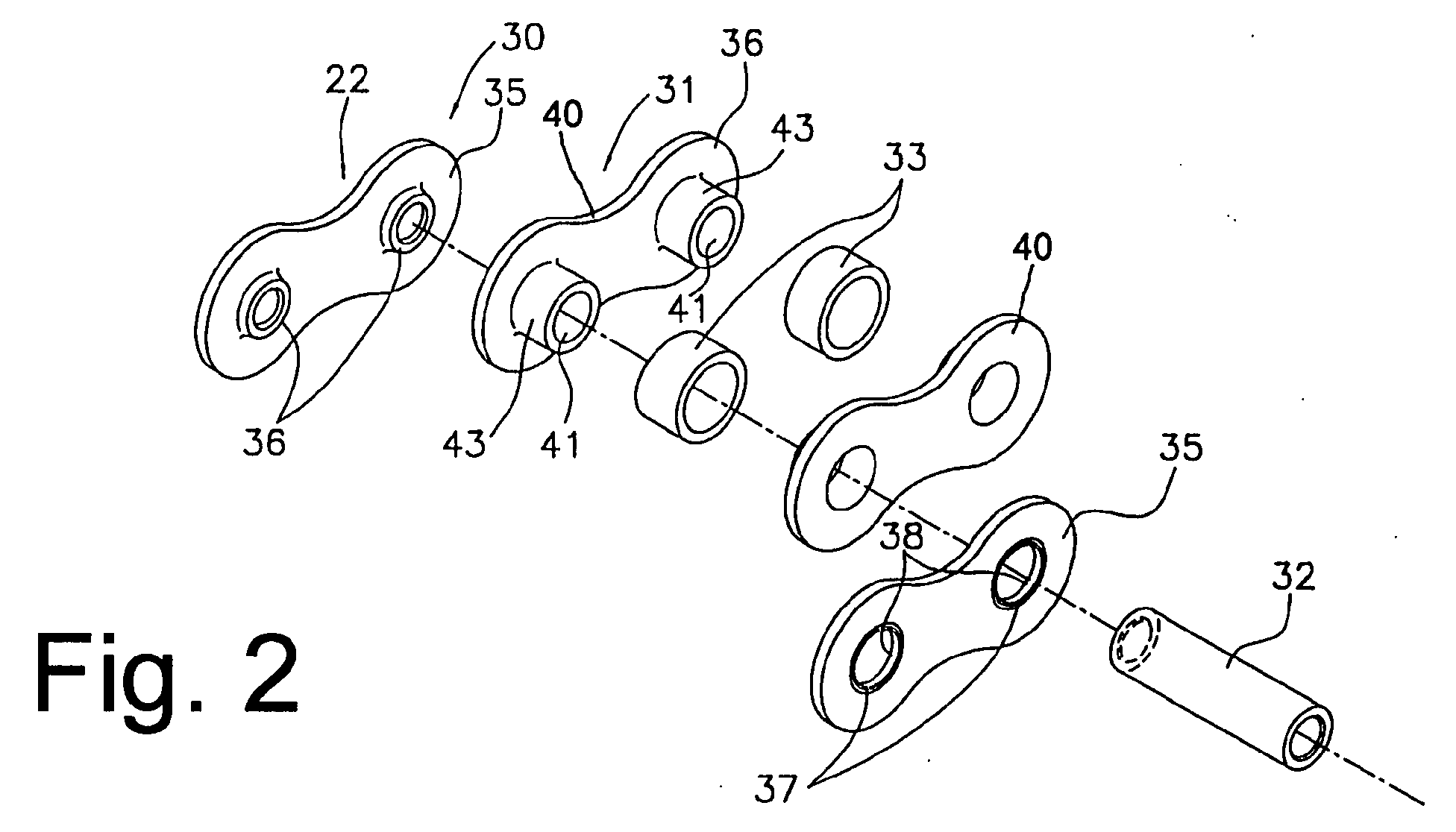
- Fig. 2 is an exploded view of a particular embodiment of bicycle chain links and a connecting pin
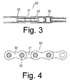
- Fig. 3 is a top view of a portion of a particular embodiment of a bicycle chain
- Fig. 4 is a side view of the bicycle chain shown in Fig. 3;
- Fig. 5 is a detailed cross sectional view of the bicycle chain in the area of the connecting pin
- Fig. 7 is a cross sectional view of a particular embodiment of a connecting pin extracting tool.
- Figs. 8A-8C illustrate the removal of a connecting pin using the connecting pin extracting tool.
- Fig. 1 is a side view of a particular embodiment of a road bicycle 1.
- Bicycle 1 comprises a diamond-shaped frame 10, a front fork 15 rotatably mounted to the front portion of frame 10, a front wheel 11 rotatably mounted to the lower part of fork 15, a rear wheel 12 rotatably mounted to the rear of frame 10, and a drive mechanism 13 for driving rear wheel 12.
- a handlebar stem 16 is mounted to the upper part of fork 15, and a drop-style handlebar 17 is mounted to a front end of handlebar stem 16.
- Front and rear brake lever assemblies 18 with integrated shifting mechanisms are mounted to opposite sides of handlebar 17.
- Front and rear brake lever assemblies 18 control respective front and rear brake mechanisms 19 for braking front wheel 11 and rear wheel 12.
- Drive unit 13 comprises a pedal crank 20 with a pair of front sprockets 20a and a pair pf pedals 25 rotatably mounted to the lower middle part of frame 10, a rear sprocket assembly 21 having a plurality of, e.g., ten rear sprockets 21a, a chain 22 that selectively engages one of the plurality of front sprockets 20a and one of the plurality of rear sprockets 21 a, a front derailleur 23 for switching chain 22 among the plurality of front sprockets 20a, and a rear derailleur 24 that switches chain 22a among the plurality of rear sprockets 21a.
- the spacing of the plurality of rear sprockets 21a is approximately 6 mm, for example, which is somewhat less than the spacing of conventional rear sprocket assemblies with seven or eight rear sprockets.
- chain 22 comprises outer links 30, inner links 31 that alternate with outer links 30, connecting pins 32 that connect the outer links 30 to the inner links 31, and a roller 33 surrounding each connecting pin 32 for rotating around the longitudinal axis of its corresponding connecting pin 32.
- Each outer link 30 comprises a pair of spaced apart outer link plates 35 oriented to face each other.
- Each outer link plate 35 is formed in the shape of a gourd that is round at both ends by punching a steel sheet having a thickness T1 of approximately 0.8 to approximately 1.0 mm.
- an interval D between the outer surfaces of the pair of outer link plates 35 ranges from approximately 5.5 to approximately 6.2 mm, and preferably approximately 5.7 to approximately 6.0 mm.
- a dish-shaped tapered first recess 36 extends inwardly from the outer surface of each outer link plate 35, a concave second recess 37 extends inwardly from each first recess 36, and a first insertion through hole 38 extends inwardly from each second recess, wherein each first through hole 38 has a smaller diameter than a side wall of its corresponding second recess 37.
- First recesses 36 may be formed by embossing using a punch press, for example, to a depth of approximately 0.2 mm to approximately 0.3 mm.
- Second recesses 37 and first insertion through holes 38 may be formed simultaneously by punching with a punch press.
- Each second recess 37 is formed into a flange, with an angled part 37a (Fig. 6) formed between it and its corresponding first insertion through hole 38.
- First recess 36 and second recess 37 are formed such that the thickness of the outer link plate 35 at the first insertion hole 38 is at least approximately 70% of the thickness T1.
- Each connecting pin 32 comprises a rod-shaped pin body that has undergone a hardening treatment to improve wear resistance.
- Each connecting pin 32 has a diameter slightly greater than the inner diameter of first insertion through holes 38.
- each connecting pin may have a diameter of approximately 3.63 mm, for example, such diameter being approximately 0.02 mm to approximately 0.08 mm greater than the inner diameter of first insertion through holes 38.
- Each connecting pin 32 is pushed through aligned pairs of the first and second insertion through holes 38 and 41 to join corresponding inner and outer links 30 and 31 together. When connecting pin 32 is pressed in, a radially inwardly contracting force as indicated by the arrow in Fig.
- each connecting pin 32 has an intermediate part 32a and expanded parts 32b, wherein expanded parts 32b are formed by crimping the end tips of connecting pin 32.
- the expanded parts 32b engage the angled parts 37a of the second recesses 37 to further axially secure connecting pin 32 to its corresponding outer link 30.
- a frusto-conically shaped recess 32c is formed in the center of each end of each connecting pin 32.
- Each recess has an inner peripheral side surface 32f and a floor 32d that faces in a longitudinal direction of connecting pin 32 away from connecting pin 32.
- Floor 32d has a floor diameter D2 of from approximately 60% to approximately 90% of an outer diameter D1 of intermediate part 32a and is smaller than the diameter of insertion through holes 38.
- diameter D2 of floor 32d is approximately 70% to approximately 80% of diameter D1 of intermediate part 32b.
- recess 32c is from approximately 0.35 mm to approximately 0.5 mm deep, preferably 0.42 mm deep. This structure facilitates the shearing of expanded parts 32b by angled parts 37a when connecting pin 32 is removed.
- connecting pin 32 When the ends of connecting pin 32 are crimped, the annular part surrounding each recess 32c more readily expands in the direction of second recess 37, thus allowing the angled part 32e of expanded part 32b to engage more precisely with angled part 37a of second recess 37.
- the axial length of the crimped connecting pin 32 is approximately ⁇ 0.3 mm relative to the distance D between the outer surfaces of the pair of outer link plates 35.
- connecting pin 32 is crimped in such a way as not to exceed 6 mm.
- each pair of inner link plates 40 are disposed facing each other, and rollers 33 are disposed around the tubular parts 43.
- Outer link plates 35 are disposed alternating with inner link plates 40 with first insertion through holes 38 aligning with second insertion through holes 41.
- Connecting pins 32 then are pushed into a first insertion through hole 38, through the corresponding second insertion through hole 41, and then through the other first insertion through hole 38 so that both ends of connecting pin 32 protrude from second recesses 37.
- Both ends of connecting pins 32 are crimped using a crimping tool 50 in the form of a flat plate, for example, to form expanded parts 32b, and the angled parts 32e of expanded parts 32b engaged the angled parts 37a of second recesses 37.
- Fig. 7 is a cross sectional view of a particular embodiment of a chain connecting pin extracting tool 110 that may be used to remove any one of the connecting pins 32.
- chain connecting pin extracting tool 110 comprises a main body 111, a pin extractor support in the form of a force applying unit 112 including a shaft 120 with a male threaded component 131 that screws into a female threaded component 122 formed in main body 111, and a pin extractor 113 connected to the tip of shaft 120.
- a wooden grip 127 is screwed into the longitudinal side of main body 111, and a storage space is formed in grip 127 for storing two connecting pins 129, one of which may be used to replace connecting pin 32 after connecting pin 32 has been removed from chain 22.
- Main body 111 is a generally hexagonal-shaped cylindrical member with a mounting recess 121 formed therein.
- a support pin 123 is mounted in mounting recess 121 for supporting pin extractor 113, and a plurality of positioning protrusions 124 are disposed in mounting recess 121 for positioning chain 22 during the extraction operation.
- Positioning protrusions 124 are formed in the same shape as the teeth of the sprockets engaged by chain 22 and are oriented such that, when chain 22 is positioned on positioning protrusions 124, connecting pin 32 aligns with pin extractor 113.
- a link support in the form of a positioning bracket 125 with a bushing 126 having a flanged tip 126a is provided for restricting axial movement of the outer links 30 of chain 22 as connecting pin 32 is pushed by pin extractor 113.
- Bushing 126 has a through hole with a diameter large enough to receive connecting pin 32 therein. The top of bushing 126 and the corresponding top part of positioning bracket 125 are open to allow the extracted connecting pin 32 to be removed.
- An extractor attachment component 132 having a smaller diameter than the male threaded component 131 of shaft 120 is formed at the inner tip of shaft 120, and a cylindrical holder 133 for detachably mounting pin extractor 113 is screwed onto extractor attachment component 132.
- An engagement hole 133a for engaging pin extractor 113 is formed in the bottom of holder 133, and a mounting hole 134 for mounting pin extractor 113 is formed in the center of extractor attachment component 132.
- Pin extractor 113 comprises a tip 140 and an integrally formed base 141, wherein tip 140 is smaller in diameter than connecting pin 32 and shorter than connecting pin 32.
- Base 141 is smaller in diameter than tip 140, at least at the border with tip 140.
- a hand grip 130 is mounted to the outer end of shaft 120 through a mounting shaft 137 that extends through a handle attachment hole 136 formed diametrically through the outer end of shaft 120.
- Hand grip 130 includes two wooden grips 138 with female threaded components that engage male threaded components 137a formed on opposite ends of mounting shaft 137.
- Rotation of hand grip 130 causes pin extractor 113 to move in a direction of a pin extractor axis defined by the longitudinal direction of pin extractor 113.
- the pin extractor axis is generally coaxial with a connecting pin axis that is defmed by the longitudinal direction of connecting pin 32 when chain 22 is positioned for removal of connecting pin 32.
- a steel ball bearing 135 is mounted in the bottom of mounting hole 134 so that pin extractor 113 is rotatable relative to shaft 120.
- pin extractor 113 rotates relative to connecting pin 32 until the contact force becomes large, and then pin extractor 113 rotates relative to shaft 120 to avoid any drilling effect on connecting pin 32.
- the rotation of pin extractor 113 relative to shaft 120 also allows pin extractor 113 to be firmly positioned on connecting pin 32 during the extraction operation.
- chain connecting pin extracting tool 110 is shown in Figs. 8A-8C.
- hand grip 130 is rotated counterclockwise (when facing hand grip 130) to retract pin extractor 113 sufficiently to allow chain 22 to be positioned in mounting recess 121.
- Chain 22 then is mounted on positioning protrusions 124 so that the connecting pin 32 to be extracted faces pin extractor 113.
- pin extractor 113 advances until the free end of tip 140 contacts connecting pin 32 as shown in Fig. 8A.
- the flanged tip 126a of bushing 126 simultaneously prevents the corresponding outer link 30 from moving in the pushed direction indicated by the arrow in Fig. 8A.
- rollers 33 may be directly placed around connecting pins 32 without forming such tubular parts 43.
- recesses 32c were formed concavely in the form of a dish, recesses 32c may have any shape.
- the size, shape, location or orientation of the various components may be changed as desired.
- Components that are shown directly connected or contacting each other may have intermediate structures disposed between them. The functions of one element may be performed by two, and vice versa. The structures and functions of one embodiment may be adopted in another embodiment.
Landscapes
- Engineering & Computer Science (AREA)
- General Engineering & Computer Science (AREA)
- Mechanical Engineering (AREA)
- Hand Tools For Fitting Together And Separating, Or Other Hand Tools (AREA)
- Devices For Conveying Motion By Means Of Endless Flexible Members (AREA)
- Gears, Cams (AREA)
Abstract
Description
- The present invention is directed to bicycles and, more particularly, to an apparatus for connecting bicycle chain links together.
- Bicycle chains engage the front sprockets at the bicycle pedal crank and the rear sprockets at the rear wheel hub for transmitting the pedaling force from the pedal crank to the rear wheel hub. As shown in Japanese Utility Model Application No. 6-49955, typical bicycle chains comprise first and second outer link plates, first and second inner link plates disposed between the first and second outer link plates so that a portion of the first outer link plate overlaps a portion of the first inner link plate and a portion of the second outer link plate overlaps a portion of the second inner link plate, a connecting pin that extends through the portion of the first outer link plate that overlaps the portion of the first inner link plate and through the portion of the second outer link plate that overlaps the portion of the second inner link plate to connect the first and second outer link plates to the first and second inner link plate, and a roller surrounding the connecting pin between the first and second inner link plates. The connecting pin has an intermediate part and first and second ends, wherein recesses are formed at the tips of the first and second ends. The first and second ends are crimped to form expanded parts that engage the outer surfaces of the first and second outer link plates. The recesses formed at the tips of the first and second ends make it easier to form the expanded parts when the first and second ends are crimped to the outer plates.
- To adjust the chain length, a chain connecting pin extracting tool is used to extract the connecting pin and thereby separate the links. A typical chain connecting pin extracting tool comprises a pin extractor in the form of a push pin that is moved back and forth by a screw, and a positioning jig that engages and positions a chain link so that the connecting pin aligns with the pin extractor. The screw advances the pin extractor to push the connecting pin out of the chain while the chain is supported by the jig. At that time, the expanded part of the connecting pin at the end pushed by the pin extractor breaks off in the form of a ring, and the connecting pin is pushed out of the chain. After the chain length has been adjusted, a special replacement connecting pin is pushed into the chain to reconnect the end links.
- When pushing the connecting pin out of a conventional chain, the outer link plates can become deformed as the expanded part breaks. This can be attributed to excessive force on the outer link plates when the expanded part is broken. If the outer link plates become deformed in this manner, the replacement connecting pin may not be held properly at the deformed outer plate when the chain links are reconnected, thus resulting in the danger of a weakly connected chain.
- The present invention is directed to various features of an apparatus for connecting bicycle chain links together. In one embodiment, a bicycle chain connecting pin comprises a pin body dimensioned to fit within an opening in a link plate of a bicycle chain, wherein the pin body has an intermediate part and first and second ends. At least one of the first and second ends has a corresponding first or second recess defining a floor that faces in a longitudinal direction of the pin away from the pin. The floor has a floor diameter of from approximately 60% to approximately 90% of an outer diameter of the intermediate part. Additional inventive features will become apparent from the description below, and such features may be combined with the above features to provide additional benefits.
- Fig. 1 is a side view of a particular embodiment of a bicycle;
- Fig. 2 is an exploded view of a particular embodiment of bicycle chain links and a connecting pin;
- Fig. 3 is a top view of a portion of a particular embodiment of a bicycle chain;
- Fig. 4 is a side view of the bicycle chain shown in Fig. 3;
- Fig. 5 is a detailed cross sectional view of the bicycle chain in the area of the connecting pin;
- Fig. 6 is a detailed cross sectional view of the bicycle chain at an upper left corner of the connecting pin;
- Fig. 7 is a cross sectional view of a particular embodiment of a connecting pin extracting tool; and
- Figs. 8A-8C illustrate the removal of a connecting pin using the connecting pin extracting tool.
- Fig. 1 is a side view of a particular embodiment of a road bicycle 1. Bicycle 1 comprises a diamond-
shaped frame 10, afront fork 15 rotatably mounted to the front portion offrame 10, afront wheel 11 rotatably mounted to the lower part offork 15, arear wheel 12 rotatably mounted to the rear offrame 10, and adrive mechanism 13 for drivingrear wheel 12. Ahandlebar stem 16 is mounted to the upper part offork 15, and a drop-style handlebar 17 is mounted to a front end ofhandlebar stem 16. Front and rear brake lever assemblies 18 with integrated shifting mechanisms are mounted to opposite sides ofhandlebar 17. Front and rear brake lever assemblies 18 control respective front andrear brake mechanisms 19 for brakingfront wheel 11 andrear wheel 12. -
Drive unit 13 comprises apedal crank 20 with a pair of front sprockets 20a and apair pf pedals 25 rotatably mounted to the lower middle part offrame 10, arear sprocket assembly 21 having a plurality of, e.g., tenrear sprockets 21a, achain 22 that selectively engages one of the plurality of front sprockets 20a and one of the plurality ofrear sprockets 21 a, afront derailleur 23 forswitching chain 22 among the plurality of front sprockets 20a, and arear derailleur 24 that switches chain 22a among the plurality ofrear sprockets 21a. In this embodiment, the spacing of the plurality ofrear sprockets 21a is approximately 6 mm, for example, which is somewhat less than the spacing of conventional rear sprocket assemblies with seven or eight rear sprockets. - As shown in Figs. 2-6,
chain 22 comprisesouter links 30,inner links 31 that alternate withouter links 30, connectingpins 32 that connect theouter links 30 to theinner links 31, and aroller 33 surrounding each connectingpin 32 for rotating around the longitudinal axis of its corresponding connectingpin 32. Eachouter link 30 comprises a pair of spaced apartouter link plates 35 oriented to face each other. Eachouter link plate 35 is formed in the shape of a gourd that is round at both ends by punching a steel sheet having a thickness T1 of approximately 0.8 to approximately 1.0 mm. In this embodiment, an interval D between the outer surfaces of the pair ofouter link plates 35 ranges from approximately 5.5 to approximately 6.2 mm, and preferably approximately 5.7 to approximately 6.0 mm. A dish-shaped taperedfirst recess 36 extends inwardly from the outer surface of eachouter link plate 35, a concavesecond recess 37 extends inwardly from eachfirst recess 36, and a first insertion throughhole 38 extends inwardly from each second recess, wherein each first throughhole 38 has a smaller diameter than a side wall of its correspondingsecond recess 37.First recesses 36 may be formed by embossing using a punch press, for example, to a depth of approximately 0.2 mm to approximately 0.3 mm.Second recesses 37 and first insertion throughholes 38 may be formed simultaneously by punching with a punch press. Eachsecond recess 37 is formed into a flange, with an angled part 37a (Fig. 6) formed between it and its corresponding first insertion throughhole 38.First recess 36 andsecond recess 37 are formed such that the thickness of theouter link plate 35 at thefirst insertion hole 38 is at least approximately 70% of the thickness T1. - Each
inner link 31 comprises a pair of spaced apartinner link plates 40 oriented to face each other. The end of eachinner link plate 40 is disposed inside a corresponding end of anouter link plate 35 such that each end of anouter link plate 35 overlaps an end of a correspondinginner link plate 40. Eachinner link plate 40 is formed in the shape of a gourd that is round at both ends by punching a steel sheet having a thickness T2 of from approximately 0.75 to approximately 0.95 mm. An inwardly extendingtubular part 43 is formed at each end of eachinner plate 40 so that corresponding pairs of thetubular parts 43 face each other with a slight gap.Rollers 33 are disposed on the outer periphery of the facingtubular parts 43 between each pair ofinner link plates 40 so as to rotate about the axis of its corresponding connectingpin 32. The inner peripheral surface of eachtubular part 43 defines a second insertion throughhole 41 having a diameter greater than the diameter of its corresponding connectingpin 32 and first insertion throughholes 38. In this embodiment, the diameter of second throughhole 41 is from approximately 0.2 mm to approximately 0.5 mm greater than the diameter of connectingpin 32. This makes it easier to insert connectingpin 32 through second insertion through holes 41.Tubular parts 43 may be formed by a drawing process, for example. A roundedouter surface 43a is formed at the transition between the main body of eachouter link plate 40 and its correspondingtubular part 43 so as not to come into contact with the inwardly extending protrusion formed by first andsecond recesses - Each connecting
pin 32 comprises a rod-shaped pin body that has undergone a hardening treatment to improve wear resistance. Each connectingpin 32 has a diameter slightly greater than the inner diameter of first insertion throughholes 38. For example, each connecting pin may have a diameter of approximately 3.63 mm, for example, such diameter being approximately 0.02 mm to approximately 0.08 mm greater than the inner diameter of first insertion throughholes 38. Each connectingpin 32 is pushed through aligned pairs of the first and second insertion throughholes outer links pin 32 is pressed in, a radially inwardly contracting force as indicated by the arrow in Fig. 6 acts on the outer peripheral surface of connectingpin 32, thus allowing connectingpin 32 to be firmly fixed to theouter link plates 35. Furthermore, each connectingpin 32 has anintermediate part 32a and expandedparts 32b, wherein expandedparts 32b are formed by crimping the end tips of connectingpin 32. The expandedparts 32b engage the angled parts 37a of thesecond recesses 37 to further axially secure connectingpin 32 to its correspondingouter link 30. - A frusto-conically
shaped recess 32c is formed in the center of each end of each connectingpin 32. Each recess has an innerperipheral side surface 32f and afloor 32d that faces in a longitudinal direction of connectingpin 32 away from connectingpin 32.Floor 32d has a floor diameter D2 of from approximately 60% to approximately 90% of an outer diameter D1 ofintermediate part 32a and is smaller than the diameter of insertion through holes 38. Preferably, diameter D2 offloor 32d is approximately 70% to approximately 80% of diameter D1 ofintermediate part 32b. Furthermore,recess 32c is from approximately 0.35 mm to approximately 0.5 mm deep, preferably 0.42 mm deep. This structure facilitates the shearing of expandedparts 32b by angled parts 37a when connectingpin 32 is removed. As a result, it is less likely that excessive force will act onouter link plate 40 as connectingpin 32 is removed, and it is possible to control the deformation ofouter link plate 40 so as to preserve the nodal strength ofchain 22. It has been found that, when the aforementioned proportion of diameter D2 to diameter D1 is over 90%, even slight axial force applied to connectingpin 32 creates the risk of shearing off expandedpart 32b. On the other hand, a proportion of diameter D2 to diameter D1 less than 60% creates the risk of excessive shearing force, thus resulting in possible deformation of theouter link plate 40. - When the ends of connecting
pin 32 are crimped, the annular part surrounding eachrecess 32c more readily expands in the direction ofsecond recess 37, thus allowing theangled part 32e of expandedpart 32b to engage more precisely with angled part 37a ofsecond recess 37. The axial length of the crimped connectingpin 32 is approximately ± 0.3 mm relative to the distance D between the outer surfaces of the pair ofouter link plates 35. Preferably, connectingpin 32 is crimped in such a way as not to exceed 6 mm. - To assemble
chain 22, thetubular parts 43 of each pair ofinner link plates 40 are disposed facing each other, androllers 33 are disposed around thetubular parts 43.Outer link plates 35 are disposed alternating withinner link plates 40 with first insertion throughholes 38 aligning with second insertion through holes 41. Connecting pins 32 then are pushed into a first insertion throughhole 38, through the corresponding second insertion throughhole 41, and then through the other first insertion throughhole 38 so that both ends of connectingpin 32 protrude fromsecond recesses 37. Both ends of connectingpins 32 are crimped using a crimpingtool 50 in the form of a flat plate, for example, to form expandedparts 32b, and theangled parts 32e of expandedparts 32b engaged the angled parts 37a ofsecond recesses 37. - Fig. 7 is a cross sectional view of a particular embodiment of a chain connecting
pin extracting tool 110 that may be used to remove any one of the connecting pins 32. As shown in Fig. 7, chain connectingpin extracting tool 110 comprises amain body 111, a pin extractor support in the form of aforce applying unit 112 including ashaft 120 with a male threaded component 131 that screws into a female threadedcomponent 122 formed inmain body 111, and apin extractor 113 connected to the tip ofshaft 120. Awooden grip 127 is screwed into the longitudinal side ofmain body 111, and a storage space is formed ingrip 127 for storing two connectingpins 129, one of which may be used to replace connectingpin 32 after connectingpin 32 has been removed fromchain 22. -
Main body 111 is a generally hexagonal-shaped cylindrical member with a mounting recess 121 formed therein. A support pin 123 is mounted in mounting recess 121 for supportingpin extractor 113, and a plurality of positioningprotrusions 124 are disposed in mounting recess 121 forpositioning chain 22 during the extraction operation. Positioningprotrusions 124 are formed in the same shape as the teeth of the sprockets engaged bychain 22 and are oriented such that, whenchain 22 is positioned on positioningprotrusions 124, connectingpin 32 aligns withpin extractor 113. A link support in the form of apositioning bracket 125 with abushing 126 having aflanged tip 126a is provided for restricting axial movement of theouter links 30 ofchain 22 as connectingpin 32 is pushed bypin extractor 113.Bushing 126 has a through hole with a diameter large enough to receive connectingpin 32 therein. The top ofbushing 126 and the corresponding top part ofpositioning bracket 125 are open to allow the extracted connectingpin 32 to be removed. - An extractor attachment component 132 having a smaller diameter than the male threaded component 131 of
shaft 120 is formed at the inner tip ofshaft 120, and acylindrical holder 133 for detachably mountingpin extractor 113 is screwed onto extractor attachment component 132. Anengagement hole 133a for engagingpin extractor 113 is formed in the bottom ofholder 133, and a mountinghole 134 for mountingpin extractor 113 is formed in the center of extractor attachment component 132.Pin extractor 113 comprises atip 140 and an integrally formedbase 141, whereintip 140 is smaller in diameter than connectingpin 32 and shorter than connectingpin 32.Base 141 is smaller in diameter thantip 140, at least at the border withtip 140. - A
hand grip 130 is mounted to the outer end ofshaft 120 through a mounting shaft 137 that extends through ahandle attachment hole 136 formed diametrically through the outer end ofshaft 120.Hand grip 130 includes twowooden grips 138 with female threaded components that engage male threadedcomponents 137a formed on opposite ends of mounting shaft 137. Rotation ofhand grip 130 causespin extractor 113 to move in a direction of a pin extractor axis defined by the longitudinal direction ofpin extractor 113. The pin extractor axis is generally coaxial with a connecting pin axis that is defmed by the longitudinal direction of connectingpin 32 whenchain 22 is positioned for removal of connectingpin 32. - A steel ball bearing 135 is mounted in the bottom of mounting
hole 134 so thatpin extractor 113 is rotatable relative toshaft 120. Thus, when the tip ofpin extractor 113contacts connecting pin 32 andhand grip 130 is rotated,pin extractor 113 rotates relative to connectingpin 32 until the contact force becomes large, and then pinextractor 113 rotates relative toshaft 120 to avoid any drilling effect on connectingpin 32. The rotation ofpin extractor 113 relative toshaft 120 also allowspin extractor 113 to be firmly positioned on connectingpin 32 during the extraction operation. - The operation of chain connecting
pin extracting tool 110 is shown in Figs. 8A-8C. Initially,hand grip 130 is rotated counterclockwise (when facing hand grip 130) to retractpin extractor 113 sufficiently to allowchain 22 to be positioned in mounting recess 121.Chain 22 then is mounted on positioningprotrusions 124 so that the connectingpin 32 to be extracted facespin extractor 113. Whenhand grip 130 is rotated clockwise,pin extractor 113 advances until the free end oftip 140contacts connecting pin 32 as shown in Fig. 8A. Theflanged tip 126a ofbushing 126 simultaneously prevents the correspondingouter link 30 from moving in the pushed direction indicated by the arrow in Fig. 8A. - Further rotation of
hand grip 130 causespin extractor 113 to push connectingpin 32 out of the opposite side ofchain 22 as shown in Fig. 8B. At this time, the expandedpart 32b of connectingpin 32 adjacent to tip 140 breaks off and remains in thesecond recess 37. If expandedpart 32b is left in that position, it will obstruct the positioning of the newspare pin 129 and prevent thespare pin 129 from being mounted properly. However, as shown in Figure 8C, whenhand grip 130 is rotated in the counterclockwise direction to retractpin extractor 113 after connectingpin 32 has been removed, the broken expandedpart 32b is caught by anabutment 145 formed at the junction oftip 140 andbase 141 of pin extractor. 113, thus allowing the broken expandedpart 32b to be removed fromsecond recess 37. - Since the diameter D2 of
floor 32d inrecess 32c is larger than recesses found in conventional connecting pins, the expandedpart 32b, which conventionally was broken at the end (top) surface and angled part when sheared off, is now sheared off around theangled part 32e and the innerperipheral surface 32f ofrecess 32c, thus requiring weaker shearing force. The forces acting onouter link plate 35 are thus weaker, with less likelihood of deformation or damage ofouter link plate 35 when connectingpin 32 is removed, thereby preserving the nodal strength ofchain 22. - While the above is a description of various embodiments of inventive features, further modifications may be employed without departing from the spirit and scope of the present invention. For example, while
tubular parts 43 were formed on theinner link plates 40, androllers 33 were disposed on thetubular parts 43,rollers 33 may be directly placed around connectingpins 32 without forming suchtubular parts 43. Whilerecesses 32c were formed concavely in the form of a dish, recesses 32c may have any shape. The size, shape, location or orientation of the various components may be changed as desired. Components that are shown directly connected or contacting each other may have intermediate structures disposed between them. The functions of one element may be performed by two, and vice versa. The structures and functions of one embodiment may be adopted in another embodiment. It is not necessary for all advantages to be present in a particular embodiment at the same time. Every feature which is unique from the prior art, alone or in combination with other features, also should be considered a separate description of further inventions by the applicant, including the structural and/or functional concepts embodied by such feature(s). Thus, the scope of the invention should not be limited by the specific structures disclosed or the apparent initial focus on a particular structure or feature.
Claims (15)
- A bicycle chain connecting pin comprising:a pin body dimensioned to fit within an opening in a link plate of a bicycle chain, wherein the pin body has an intermediate part and first and second ends, wherein at least one of the first and second ends has a corresponding first or second recess defining a floor that faces in a longitudinal direction of the pin away from the pin, and wherein the floor has a floor diameter of from approximately 60% to approximately 90% of an outer diameter of the intermediate part.
- The connecting pin according to claim 1 wherein the floor diameter is from approximately 70% to approximately 80% of the outer diameter of the intermediate part.
- The connecting pin according to claim 1 or 2 wherein the pin body has a cylindrical shape.
- The connecting pin according to claim 1, 2 or 3 wherein the at least one of the first or second recess has a round shape.
- The connecting pin according to any one of claims 1 to 4 wherein the at least one of the first or second recess is completely surrounded by the pin body.
- The connecting pin according to any one of claims 1 to 5 wherein the pin body has a diametrically expanded part at the at least one of the first or second recess.
- The connecting pin according to claim 6 wherein the expanded part completely surrounds the at least one of the first or second recess.
- The connecting pin according to any one of claims 1 to 7 wherein the first end has the corresponding first recess, and wherein the second end has the corresponding second recess.
- The connecting pin according to claim 8 wherein the first recess defines a first floor that faces in the longitudinal direction of the pin away from the pin, wherein the first floor has a first floor diameter of from approximately 60% to approximately 90% of the outer diameter of the intermediate part, wherein the second recess defines a second floor that faces in the longitudinal direction of the pin away from the pin, and wherein the second floor has a second floor diameter of from approximately 60% to approximately 90% of the outer diameter of the intermediate part.
- The connecting pin according to claim 9 wherein the pin body has a first diametrically expanded part that completely surrounds the first recess, wherein the pin body has a second diametrically expanded part that completely surrounds the second recess, wherein the first floor diameter is from approximately 70% to approximately 80% of the outer diameter of the intermediate part, and wherein the second floor diameter is from approximately 70% to approximately 80% of the outer diameter of the intermediate part.
- A bicycle chain apparatus comprising:first and second outer link plates;first and second inner link plates disposed between the first and second outer link plates so that a portion of the first outer link plate overlaps a portion of the first inner link plate and a portion of the second outer link plate overlaps a portion of the second inner link plate;a connecting pin according to any one of claims 1 to 9 that extends through the portion of the first outer link plate that overlaps the portion of the first inner link plate and through the portion of the second outer link plate that overlaps the portion of the second inner link plate to connect the first and second outer link plates to the first and second inner link plates.
- The apparatus according to claim 11 wherein an axial length of the connecting pin is less than or equal to a distance between outer surfaces of the first and second outer link plates.
- The apparatus according to claim 11 or 12 wherein the first inner link plate has a first tubular portion that extends toward the second inner link plate, and wherein the second inner link plate has a second tubular portion that extends toward and faces the first tubular portion.
- The apparatus according to claim 13 wherein the connecting pin extends through the first and second tubular portions.
- The apparatus according to claim 13 or 14 further comprising a roller that surrounds the first and second tubular portions.
Applications Claiming Priority (2)
| Application Number | Priority Date | Filing Date | Title |
|---|---|---|---|
| JP2004163298A JP2005343254A (en) | 2004-06-01 | 2004-06-01 | Chain for bicycle |
| JP2004163298 | 2004-06-01 |
Publications (3)
| Publication Number | Publication Date |
|---|---|
| EP1602856A2 true EP1602856A2 (en) | 2005-12-07 |
| EP1602856A3 EP1602856A3 (en) | 2006-02-08 |
| EP1602856B1 EP1602856B1 (en) | 2009-08-12 |
Family
ID=34936891
Family Applications (1)
| Application Number | Title | Priority Date | Filing Date |
|---|---|---|---|
| EP05011251A Ceased EP1602856B1 (en) | 2004-06-01 | 2005-05-24 | Bicycle chain |
Country Status (7)
| Country | Link |
|---|---|
| US (1) | US7473198B2 (en) |
| EP (1) | EP1602856B1 (en) |
| JP (1) | JP2005343254A (en) |
| CN (1) | CN100467906C (en) |
| BR (1) | BRPI0502044A (en) |
| DE (1) | DE602005015912D1 (en) |
| TW (1) | TW200540063A (en) |
Families Citing this family (22)
| Publication number | Priority date | Publication date | Assignee | Title |
|---|---|---|---|---|
| US7325391B1 (en) * | 2007-03-02 | 2008-02-05 | Shimano Inc. | Bicycle chain |
| ITMI20071660A1 (en) | 2007-08-09 | 2009-02-10 | Campagnolo Srl | MOTION BIKE TRANSMISSION SYSTEM |
| DE202015105857U1 (en) | 2014-11-18 | 2016-02-18 | Shimano Inc. | bicycle chain |
| DE102016009814A1 (en) * | 2015-09-09 | 2017-03-09 | Sram Deutschland Gmbh | Roller chain inner link |
| US10703441B2 (en) | 2015-07-03 | 2020-07-07 | Sram Deutschland Gmbh | Drive arrangement for a bicycle |
| EP3141776B1 (en) * | 2015-09-09 | 2023-08-23 | SRAM Deutschland GmbH | Role chain internal tab |
| ITUB20154794A1 (en) * | 2015-11-06 | 2017-05-06 | Campagnolo Srl | Bicycle chain and motion transmission system comprising this chain |
| US10946931B2 (en) | 2017-09-22 | 2021-03-16 | Shimano Inc. | Bicycle rear sprocket assembly and bicycle drive train |
| US11059541B2 (en) | 2017-05-30 | 2021-07-13 | Shimano Inc. | Bicycle hub assembly |
| US10752320B2 (en) | 2017-09-22 | 2020-08-25 | Shimano Inc. | Bicycle rear hub assembly |
| US11078987B2 (en) * | 2017-08-08 | 2021-08-03 | Shimano Inc. | Bicycle chain |
| DE102018116401A1 (en) * | 2017-08-08 | 2019-02-14 | Shimano Inc. | BICYCLE CHAIN |
| US10618598B2 (en) | 2017-09-29 | 2020-04-14 | Shimano Inc. | Bicycle chain |
| US10473187B2 (en) * | 2017-09-11 | 2019-11-12 | Ming Chang Traffic Parts Manufacturing Co., Ltd. | Chain assembly |
| US10794452B2 (en) * | 2018-04-06 | 2020-10-06 | Shimano Inc. | Bicycle chain |
| EP3748190B1 (en) * | 2019-06-04 | 2025-11-19 | iwis mobility systems GmbH & Co. KG | Optimized bolt join geometry |
| JP7718796B2 (en) * | 2019-07-19 | 2025-08-05 | 株式会社椿本チエイン | Bicycle chain |
| EP3907052B1 (en) | 2020-05-05 | 2025-09-03 | Andreas Stihl AG & Co. KG | Saw chain |
| JP2022099213A (en) * | 2020-12-22 | 2022-07-04 | 株式会社椿本チエイン | chain |
| CN114718989A (en) * | 2020-12-22 | 2022-07-08 | 株式会社椿本链条 | chain |
| TWI842336B (en) * | 2023-01-12 | 2024-05-11 | 保忠精密工具股份有限公司 | Bicycle special tool with composite function |
| JP2026066013A (en) * | 2024-10-04 | 2026-04-16 | 大同工業株式会社 | Bicycle chain |
Citations (2)
| Publication number | Priority date | Publication date | Assignee | Title |
|---|---|---|---|---|
| JPH0441039B2 (en) | 1984-01-19 | 1992-07-07 | Shiaazu Mfg Co | |
| JPH0649955U (en) | 1992-10-30 | 1994-07-08 | トーソク株式会社 | Air micrometer device |
Family Cites Families (14)
| Publication number | Priority date | Publication date | Assignee | Title |
|---|---|---|---|---|
| US2773971A (en) * | 1954-08-04 | 1956-12-11 | Chains Inc | Chains and the like |
| US4050323A (en) * | 1976-01-12 | 1977-09-27 | Anson Thomas I | Pintle-type industrial conveyor chain |
| US4464151A (en) * | 1981-07-30 | 1984-08-07 | Rexnord Inc. | Sealed chain joint |
| US4978327A (en) * | 1990-04-04 | 1990-12-18 | Wu Chia L | Coupling portion of a chain |
| JPH0441039A (en) | 1990-06-07 | 1992-02-12 | Fukusen Kogyo Kofun Yugenkoshi | Manufacture of roller chain |
| GB2257221B (en) | 1991-07-03 | 1994-11-16 | Chia Long Wu | Chain pin |
| GB2260592A (en) * | 1991-10-16 | 1993-04-21 | Stefan Karp | A chain |
| US5465568A (en) | 1995-01-17 | 1995-11-14 | Yaban Chain Industrial Co., Ltd. | Chain structure for bicycles |
| JP2977495B2 (en) * | 1996-09-02 | 1999-11-15 | 株式会社椿本チエイン | Low noise roller chain |
| JPH1082454A (en) * | 1996-09-06 | 1998-03-31 | Tsubakimoto Chain Co | Chain with swelling seal |
| JP2002013596A (en) * | 2000-06-30 | 2002-01-18 | Daido Kogyo Co Ltd | Low noise roller chain |
| US6394923B1 (en) * | 2000-07-05 | 2002-05-28 | Ming Chang Traffic Manufacturing Co., Ltd. | Drive chain |
| EP1245862B1 (en) * | 2001-03-29 | 2006-07-26 | SRAM Deutschland GmbH | Driving chain for a bicycle or similar |
| JP3656848B2 (en) * | 2003-02-27 | 2005-06-08 | 株式会社椿本チエイン | Automotive engine timing chain |
-
2004
- 2004-06-01 JP JP2004163298A patent/JP2005343254A/en not_active Withdrawn
-
2005
- 2005-03-28 TW TW094109567A patent/TW200540063A/en unknown
- 2005-04-25 US US10/908,011 patent/US7473198B2/en not_active Expired - Fee Related
- 2005-04-29 CN CNB2005100687096A patent/CN100467906C/en not_active Expired - Fee Related
- 2005-05-24 DE DE602005015912T patent/DE602005015912D1/en not_active Expired - Lifetime
- 2005-05-24 EP EP05011251A patent/EP1602856B1/en not_active Ceased
- 2005-05-27 BR BR0502044-1A patent/BRPI0502044A/en not_active IP Right Cessation
Patent Citations (2)
| Publication number | Priority date | Publication date | Assignee | Title |
|---|---|---|---|---|
| JPH0441039B2 (en) | 1984-01-19 | 1992-07-07 | Shiaazu Mfg Co | |
| JPH0649955U (en) | 1992-10-30 | 1994-07-08 | トーソク株式会社 | Air micrometer device |
Also Published As
| Publication number | Publication date |
|---|---|
| BRPI0502044A (en) | 2006-01-24 |
| EP1602856B1 (en) | 2009-08-12 |
| TW200540063A (en) | 2005-12-16 |
| DE602005015912D1 (en) | 2009-09-24 |
| US20050266949A1 (en) | 2005-12-01 |
| CN100467906C (en) | 2009-03-11 |
| CN1704624A (en) | 2005-12-07 |
| US7473198B2 (en) | 2009-01-06 |
| EP1602856A3 (en) | 2006-02-08 |
| JP2005343254A (en) | 2005-12-15 |
Similar Documents
| Publication | Publication Date | Title |
|---|---|---|
| EP1602856B1 (en) | Bicycle chain | |
| EP1413506B1 (en) | Bicycle hub axle assembly | |
| JP3583385B2 (en) | Bicycle sprocket assembly and bicycle large sprocket | |
| US6435622B1 (en) | Bicycle hub with threaded spacer and detachable freewheel | |
| US8905880B2 (en) | Chain connecting pin | |
| US6497314B2 (en) | Bicycle hub with sliding engagement member and detachable freewheel | |
| US10328995B2 (en) | Multi-sprocket arrangement for a bicycle | |
| US9180929B2 (en) | Sprocket assembly | |
| EP1495879B1 (en) | Bicycle hub outer and bicycle hub | |
| EP1634805B1 (en) | Bicycle headset | |
| US8371660B2 (en) | Load transmitting insert for a soft spline body | |
| EP0766017B1 (en) | Bicycle freewheel | |
| TWI277569B (en) | A fixing mechanism of a bicycle crank | |
| US7082747B2 (en) | Chain connecting pin extracting apparatus | |
| KR20170097032A (en) | A mechanism for releasing electrode caps from a spot welding gun | |
| EP2128476A1 (en) | Floating type disc brake | |
| KR20110075299A (en) | Method for producing a crank arm for bicycle, bicycle crank arm manufactured thereby | |
| FR2773198A1 (en) | METAL FIXING ELEMENT AND MANUFACTURING METHOD THEREOF | |
| WO2023032533A1 (en) | Bicycle chain and connecting pin member for bicycle chain | |
| EP0870122A1 (en) | Device for guiding the translation and adjusting the position of two mutually movable parts | |
| TWI415753B (en) | Drive body for bicycle wheel hub | |
| CN218662248U (en) | Exempt from crank subassembly of instrument dismouting | |
| WO2025173230A1 (en) | Jig for removing drive roller | |
| JP2015166118A (en) | Stud bolt loosening tool | |
| DE10358007B3 (en) | Bicycle with two pedaling modes has rotating shaft tube which is provided with pedaling mode change apparatus and rotating shaft structure with ends respectively connected to two cranks coupled to pedals |
Legal Events
| Date | Code | Title | Description |
|---|---|---|---|
| PUAI | Public reference made under article 153(3) epc to a published international application that has entered the european phase |
Free format text: ORIGINAL CODE: 0009012 |
|
| AK | Designated contracting states |
Kind code of ref document: A2 Designated state(s): AT BE BG CH CY CZ DE DK EE ES FI FR GB GR HU IE IS IT LI LT LU MC NL PL PT RO SE SI SK TR |
|
| AX | Request for extension of the european patent |
Extension state: AL BA HR LV MK YU |
|
| PUAL | Search report despatched |
Free format text: ORIGINAL CODE: 0009013 |
|
| AK | Designated contracting states |
Kind code of ref document: A3 Designated state(s): AT BE BG CH CY CZ DE DK EE ES FI FR GB GR HU IE IS IT LI LT LU MC NL PL PT RO SE SI SK TR |
|
| AX | Request for extension of the european patent |
Extension state: AL BA HR LV MK YU |
|
| 17P | Request for examination filed |
Effective date: 20060314 |
|
| RAP1 | Party data changed (applicant data changed or rights of an application transferred) |
Owner name: SHIMANO INC. |
|
| AKX | Designation fees paid |
Designated state(s): DE |
|
| 17Q | First examination report despatched |
Effective date: 20061005 |
|
| GRAP | Despatch of communication of intention to grant a patent |
Free format text: ORIGINAL CODE: EPIDOSNIGR1 |
|
| GRAS | Grant fee paid |
Free format text: ORIGINAL CODE: EPIDOSNIGR3 |
|
| GRAA | (expected) grant |
Free format text: ORIGINAL CODE: 0009210 |
|
| AK | Designated contracting states |
Kind code of ref document: B1 Designated state(s): DE |
|
| REF | Corresponds to: |
Ref document number: 602005015912 Country of ref document: DE Date of ref document: 20090924 Kind code of ref document: P |
|
| PLBE | No opposition filed within time limit |
Free format text: ORIGINAL CODE: 0009261 |
|
| STAA | Information on the status of an ep patent application or granted ep patent |
Free format text: STATUS: NO OPPOSITION FILED WITHIN TIME LIMIT |
|
| 26N | No opposition filed |
Effective date: 20100517 |
|
| PGFP | Annual fee paid to national office [announced via postgrant information from national office to epo] |
Ref country code: DE Payment date: 20190514 Year of fee payment: 15 |
|
| REG | Reference to a national code |
Ref country code: DE Ref legal event code: R119 Ref document number: 602005015912 Country of ref document: DE |
|
| PG25 | Lapsed in a contracting state [announced via postgrant information from national office to epo] |
Ref country code: DE Free format text: LAPSE BECAUSE OF NON-PAYMENT OF DUE FEES Effective date: 20201201 |