EP1602536A2 - Side curtain air bag assembly - Google Patents
Side curtain air bag assembly Download PDFInfo
- Publication number
- EP1602536A2 EP1602536A2 EP05019891A EP05019891A EP1602536A2 EP 1602536 A2 EP1602536 A2 EP 1602536A2 EP 05019891 A EP05019891 A EP 05019891A EP 05019891 A EP05019891 A EP 05019891A EP 1602536 A2 EP1602536 A2 EP 1602536A2
- Authority
- EP
- European Patent Office
- Prior art keywords
- inflation fluid
- container
- closure member
- vehicle occupant
- protection device
- Prior art date
- Legal status (The legal status is an assumption and is not a legal conclusion. Google has not performed a legal analysis and makes no representation as to the accuracy of the status listed.)
- Granted
Links
Images


Classifications
-
- B—PERFORMING OPERATIONS; TRANSPORTING
- B60—VEHICLES IN GENERAL
- B60R—VEHICLES, VEHICLE FITTINGS, OR VEHICLE PARTS, NOT OTHERWISE PROVIDED FOR
- B60R21/00—Arrangements or fittings on vehicles for protecting or preventing injuries to occupants or pedestrians in case of accidents or other traffic risks
- B60R21/02—Occupant safety arrangements or fittings, e.g. crash pads
- B60R21/16—Inflatable occupant restraints or confinements designed to inflate upon impact or impending impact, e.g. air bags
- B60R21/26—Inflatable occupant restraints or confinements designed to inflate upon impact or impending impact, e.g. air bags characterised by the inflation fluid source or means to control inflation fluid flow
- B60R21/268—Inflatable occupant restraints or confinements designed to inflate upon impact or impending impact, e.g. air bags characterised by the inflation fluid source or means to control inflation fluid flow using instantaneous release of stored pressurised gas
-
- B—PERFORMING OPERATIONS; TRANSPORTING
- B60—VEHICLES IN GENERAL
- B60R—VEHICLES, VEHICLE FITTINGS, OR VEHICLE PARTS, NOT OTHERWISE PROVIDED FOR
- B60R21/00—Arrangements or fittings on vehicles for protecting or preventing injuries to occupants or pedestrians in case of accidents or other traffic risks
- B60R2021/0002—Type of accident
- B60R2021/0018—Roll-over
-
- B—PERFORMING OPERATIONS; TRANSPORTING
- B60—VEHICLES IN GENERAL
- B60R—VEHICLES, VEHICLE FITTINGS, OR VEHICLE PARTS, NOT OTHERWISE PROVIDED FOR
- B60R21/00—Arrangements or fittings on vehicles for protecting or preventing injuries to occupants or pedestrians in case of accidents or other traffic risks
- B60R21/02—Occupant safety arrangements or fittings, e.g. crash pads
- B60R21/16—Inflatable occupant restraints or confinements designed to inflate upon impact or impending impact, e.g. air bags
- B60R21/26—Inflatable occupant restraints or confinements designed to inflate upon impact or impending impact, e.g. air bags characterised by the inflation fluid source or means to control inflation fluid flow
- B60R2021/26058—Inflatable occupant restraints or confinements designed to inflate upon impact or impending impact, e.g. air bags characterised by the inflation fluid source or means to control inflation fluid flow using a combination of inflators
-
- B—PERFORMING OPERATIONS; TRANSPORTING
- B60—VEHICLES IN GENERAL
- B60R—VEHICLES, VEHICLE FITTINGS, OR VEHICLE PARTS, NOT OTHERWISE PROVIDED FOR
- B60R21/00—Arrangements or fittings on vehicles for protecting or preventing injuries to occupants or pedestrians in case of accidents or other traffic risks
- B60R21/02—Occupant safety arrangements or fittings, e.g. crash pads
- B60R21/16—Inflatable occupant restraints or confinements designed to inflate upon impact or impending impact, e.g. air bags
- B60R21/26—Inflatable occupant restraints or confinements designed to inflate upon impact or impending impact, e.g. air bags characterised by the inflation fluid source or means to control inflation fluid flow
- B60R2021/26094—Inflatable occupant restraints or confinements designed to inflate upon impact or impending impact, e.g. air bags characterised by the inflation fluid source or means to control inflation fluid flow characterised by fluid flow controlling valves
-
- B—PERFORMING OPERATIONS; TRANSPORTING
- B60—VEHICLES IN GENERAL
- B60R—VEHICLES, VEHICLE FITTINGS, OR VEHICLE PARTS, NOT OTHERWISE PROVIDED FOR
- B60R21/00—Arrangements or fittings on vehicles for protecting or preventing injuries to occupants or pedestrians in case of accidents or other traffic risks
- B60R21/02—Occupant safety arrangements or fittings, e.g. crash pads
- B60R21/16—Inflatable occupant restraints or confinements designed to inflate upon impact or impending impact, e.g. air bags
- B60R21/26—Inflatable occupant restraints or confinements designed to inflate upon impact or impending impact, e.g. air bags characterised by the inflation fluid source or means to control inflation fluid flow
- B60R21/268—Inflatable occupant restraints or confinements designed to inflate upon impact or impending impact, e.g. air bags characterised by the inflation fluid source or means to control inflation fluid flow using instantaneous release of stored pressurised gas
- B60R2021/2685—Inflatable occupant restraints or confinements designed to inflate upon impact or impending impact, e.g. air bags characterised by the inflation fluid source or means to control inflation fluid flow using instantaneous release of stored pressurised gas comprising a plurality of pressure chambers
-
- B—PERFORMING OPERATIONS; TRANSPORTING
- B60—VEHICLES IN GENERAL
- B60R—VEHICLES, VEHICLE FITTINGS, OR VEHICLE PARTS, NOT OTHERWISE PROVIDED FOR
- B60R21/00—Arrangements or fittings on vehicles for protecting or preventing injuries to occupants or pedestrians in case of accidents or other traffic risks
- B60R21/02—Occupant safety arrangements or fittings, e.g. crash pads
- B60R21/16—Inflatable occupant restraints or confinements designed to inflate upon impact or impending impact, e.g. air bags
- B60R21/23—Inflatable members
- B60R21/231—Inflatable members characterised by their shape, construction or spatial configuration
- B60R21/232—Curtain-type airbags deploying mainly in a vertical direction from their top edge
-
- Y—GENERAL TAGGING OF NEW TECHNOLOGICAL DEVELOPMENTS; GENERAL TAGGING OF CROSS-SECTIONAL TECHNOLOGIES SPANNING OVER SEVERAL SECTIONS OF THE IPC; TECHNICAL SUBJECTS COVERED BY FORMER USPC CROSS-REFERENCE ART COLLECTIONS [XRACs] AND DIGESTS
- Y10—TECHNICAL SUBJECTS COVERED BY FORMER USPC
- Y10T—TECHNICAL SUBJECTS COVERED BY FORMER US CLASSIFICATION
- Y10T137/00—Fluid handling
- Y10T137/1624—Destructible or deformable element controlled
- Y10T137/1632—Destructible element
- Y10T137/1692—Rupture disc
- Y10T137/1714—Direct pressure causes disc to burst
- Y10T137/1729—Dome shape
- Y10T137/1737—Reverse buckling
Definitions
- the present invention relates to an inflator which provides inflation fluid to inflate an inflatable vehicle occupant protection device and, more specifically, to an inflator in which a rupturable closure member is supported.
- An inflatable vehicle occupant protection device such as a side curtain or an air bag, is inflated upon the occurrence of a vehicle condition requiring inflation of the side curtain or air bag.
- an inflator is actuated to provide inflation fluid which inflates the side curtain or air bag into the vehicle occupant compartment.
- the inflator includes a container defining an inflation fluid pressure chamber with an outlet passage.
- a rupturable closure member is fixed to the container to block flow of inflation fluid through the outlet passage.
- the inflator further includes an electrically actuatable initiator which, when actuated, causes the closure member to rupture so that inflation fluid in the pressure chamber can flow from the inflator.
- the present invention is an inflator for providing inflation fluid to inflate an inflatable vehicle occupant protection device.
- the inflator includes a container storing inflation fluid under pressure.
- the container has an outlet passage through which inflation fluid flows from the container.
- a rupturable closure member fixed to the container blocks flow of inflation fluid through the outlet passage.
- a support for the rupturable closure member defines a chamber adjacent the rupturable closure member.
- the rupturable closure member has a first portion deformed into the chamber by the pressure of the inflation fluid and a second ring-shaped portion encircling the first portion.
- An initiator ruptures the closure member by shearing the first portion from the second portion when actuated.
- the present invention relates to a vehicle occupant safety apparatus.
- the present invention relates to an inflatable vehicle occupant protection device, such as a side curtain assembly, for helping to protect a vehicle occupant in the event of a side impact to a vehicle.
- Fig. 1 illustrates schematically a vehicle safety apparatus 10 for helping to protect an occupant of a vehicle 12.
- the safety apparatus 10 includes an inflatable vehicle occupant protection device in the form of a side curtain 14.
- the side curtain 14 is mounted adjacent the side structure 16 of the vehicle 12.
- a fill tube 20 extends into the side curtain 14.
- An actuatable inflator 22 when actuated, directs fluid into the fill tube 20 which, in turn, directs fluid into the inflatable side curtain 14 to inflate the side curtain.
- the side curtain 14 is inflated from a deflated and stowed condition (not shown) to an inflated condition, as illustrated in Fig. 1. In its inflated condition, the side curtain 14 is positioned between the side structure of the vehicle and a vehicle occupant.
- the side curtain 14 is made of a material having a low permeability so that the side curtain remains inflated for a long period of time, such as seven seconds or longer.
- the vehicle 12 includes a sensor 24, known in the art, for sensing a side impact to the vehicle and/or a vehicle rollover, to actuate the inflator 22.
- the sensor 24 may include vehicle electric circuitry for actuating the inflator 22 in response to sensing a side impact to the vehicle and/or a vehicle rollover.
- the sensor 24 provides an electric signal over lead wires 26 to the inflator 22, when the inflator is to be actuated.
- the inflator 22 (Fig. 2) comprises a source of inflation fluid for the side curtain 14.
- the inflator 22 includes a container 30 having a generally elongate configuration including a main body portion 32 and an end cap 34.
- the end cap 34 is affixed to an open end 33 of the main body portion 32 by friction welding.
- the end cap 34 could, however, be connected to the main body portion 32 in any manner known in the art, such as using laser welds, brazing or screw threads.
- the main body portion 32 of the container 30 has a tubular, cylindrical configuration including an axially extending cylindrical side wall 40.
- the side wall 40 has a cylindrical inner surface 42 centered on a longitudinal central axis 44 of the inflator 22.
- a second end portion 46 of the main body portion 32 is closed by a domed end wall 48.
- the side wall 44 and the end wall 48 define a chamber 50 in the container 30.
- the chamber 50 contains pressurized inflation fluid.
- the inflation fluid stored in the chamber 50 preferably consists essentially of helium at a storage pressure within the range of about 4,000 psi to about 7,000 psi.
- the inflation fluid may, however, have any other composition and storage pressure suitable for inflating the side curtain 14.
- the end cap 34 (Figs. 2 and 3) of the container 30 has a generally cylindrical configuration including an axially extending cylindrical side wall 70 and an end surface 72.
- An annular array of inflation fluid outlet passages 76 are formed in the side wall 70 of the end cap 34.
- the flow area, number and/or configuration of the outlet passages 76 may be selected to restrict or otherwise control the flow of inflation fluid into the side curtain 14 through the fill tube 20, which is connected in a known manner to the end cap 34, as illustrated schematically in Fig. 1.
- the end cap 34 includes a surface 78 (Fig. 2) which extends generally parallel to the end surface 72.
- a passage 80 extends axially through the end cap 34 and intersects the surface 78.
- the passage 80 conducts inflation fluid from the chamber 50 to the outlet passages 76.
- the passage 80 is centered on the axis 44.
- a rupturable closure member 92 (Figs. 2 and 3), such as a rupture disk, is affixed to the surface 78 by a laser weld 94.
- the rupture disk 92 could, however, be connected to the surface 78 in any manner well known in the art, such as by brazing, projection welding or electron beam welding.
- the rupture disk 92 is centered on the axis 44 and blocks the flow of inflation fluid through the passage 80 and to the passages 76.
- An initiator 98 centered on the axis 44 is housed in a hollow support 100 which supports the closure member 92.
- Lead wires 26 extend from connector pins 101 of the initiator 98 to receive the electrical signal from the sensor 24.
- the support 100 is centered on the axis 44.
- the support 100 (Figs. 2 and 3) has a flange 102 which engages the end surface 72 of the end cap 34.
- the flange 102 extends radially outward of the support 100 and also engages a radially extending base 104 of the initiator 98.
- An annular rim portion 106 extends from the end surface 72.
- the rim portion 106 initially projects axially away from the end surface 72 and is subsequently crimped around the base 104 of the initiator 98 to hold the initiator and the support 100 in place in the end cap 34.
- the initiator 98 and the support 100 may be welded to the end cap 34 to retain the initiator and the support in the end cap.
- the support 100 projects inwardly along the axis 44 into abutment with the closure member 92.
- the support 100 is thus mounted in a load bearing relationship with the closure member 92. More specifically, the closure member 92 is subjected to the storage pressure of the inflation fluid in the chamber 50. Therefore, the closure member 92 transmits a fluid storage pressure force axially outward against the support 100.
- the support 100 transmits the storage pressure force to the end surface 72 of the end cap 34 where the initiator 98 adjoins the crimped rim 106 of the end surface 72.
- the support 100 defines a chamber 110.
- An end portion 112 of the support 100 has a circular rim 114 engaging the closure member 92.
- the rim 114 defines an opening 116 into the chamber 110.
- the closure member 92 has a central dome-shaped portion 122 extending into the chamber 110.
- a portion 124 of the closure member 92 encircles the dome-shaped portion 122.
- the portion 124 of the closure member 92 extends from the circular rim 114 of the support 100 to the surface 78 of the end cap 34.
- a portion 126 of the closure member 92 encircles the portion 124 and is welded to the surface 78.
- the closure member 92 When the chamber 50 is not filled with inflation fluid, as shown in Fig. 4, the closure member 92 is a flat disk. The closure member 92 is spaced from the rim 114 of the support 100. During the subsequent loading of the closure member 92 by the pressure of the inflation fluid, the closure member is stressed and undergoes plastic deformation into the chamber 110. The closure member 92 deforms from the flat disk shown in Fig. 4 into the shape shown in Fig. 3. A work hardening of the closure member 92 occurs during the plastic deformation.
- the initiator 98 Upon receiving of an electric signal from the sensor 24, the initiator 98 is actuated in a known manner to produce a shock wave and combustion gas.
- the portion 124 of the closure member 92 continues to block the passage 80.
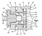
- the pressure generated by the inflation fluid is supported only by the strength of the portion 124 when the dome 122 is removed.
- the pressure of the inflation fluid causes the portion 124 of the closure member 92 to rip and petal away from the support 100 to the position shown in Fig. 7, providing a flow of the inflation fluid through the passage 80 and to the outlet passages 76' and thereafter to the side curtain 14.
- inflator 22 is shown being used with a side curtain 14, the inflator could be used in any known inflatable vehicle occupant protection device such as air bags, inflatable seat belts, inflatable knee bolsters, inflatable air bags to operate knee bolsters, and inflatable head liners.
- any known inflatable vehicle occupant protection device such as air bags, inflatable seat belts, inflatable knee bolsters, inflatable air bags to operate knee bolsters, and inflatable head liners.
Landscapes
- Physics & Mathematics (AREA)
- Fluid Mechanics (AREA)
- Engineering & Computer Science (AREA)
- Mechanical Engineering (AREA)
- Air Bags (AREA)
Abstract
Description
Claims (6)
- An apparatus (10) for helping to protect an occupant of a vehicle (12) that has a side structure (16), said apparatus (10) comprising:an inflatable vehicle occupant protection device (14) that is inflatable from a deflated and stowed condition into an inflated condition between the side structure (16) of the vehicle (12) and a vehicle occupant; andan inflator (22) for providing inflation fluid to said inflatable vehicle occupant protection device (14) to inflate said inflatable vehicle occupant protection device (14) from said deflated stowed condition to said inflated condition and maintain said inflatable vehicle occupant protection device (14) in said inflated condition for at least seven seconds, said inflation fluid consisting essentially of helium stored under pressure.
- Apparatus as defined in claim 1, wherein said inflator (22) comprises:a container (30) for storing said inflation fluid under pressure, said container (30) having an outlet passage (76, 80) through which said inflation fluid flows from said container (30) toward said inflatable vehicle occupant protection device (14);a rupturable closure member (92) fixed to said container (30) and blocking flow of said inflation fluid through said outlet passage (76, 80); andan initiator (98) which, when actuated, causes said closure member (92) to rupture to allow said inflation fluid to flow through said outlet passage (76, 80).
- Apparatus as defined in claim 2, further comprising a support (100) for supporting said closure member (92) against the pressure of said inflation fluid in said container (30), said initiator (98), when actuated, rupturing said closure member (92) and opening said outlet passage (76, 80) to provide a flow of inflation fluid from said container (30) through said outlet passage (76, 80).
- Apparatus as defined in claim 2 or 3, wherein said initiator (98), when actuated, shears away a portion (122) of said closure member (92) to open said outlet passage (76, 80).
- Apparatus as defined in claim 1, wherein said inflator (22) comprises:container means (30) for containing inflation fluid under pressure, said container means (30) having at least one openable portion (92) for releasing inflation fluid to flow out of said container means (30);first output means connected with said container means (30) for releasing inflation fluid from said inflator (22) at a relatively high rate over a relatively short period of time; andsecond output means connected with said container means (30) for releasing inflation fluid from said inflator (22) at a relatively low rate for a relatively long period of time.
- Apparatus as defined in claim 1, further comprising a fill tube (20) having a portion located in said inflatable vehicle occupant protection device (14), said fill tube (20) delivering said inflation fluid to said inflatable vehicle occupant protection device (14) to inflate said inflatable vehicle occupant protection device (14).
Applications Claiming Priority (3)
| Application Number | Priority Date | Filing Date | Title |
|---|---|---|---|
| US371776 | 1982-04-26 | ||
| US09/371,776 US7131663B1 (en) | 1999-08-10 | 1999-08-10 | Inflator for inflatable vehicle occupant protection device |
| EP00112245A EP1075988B1 (en) | 1999-08-10 | 2000-06-07 | Inflator with rupturable closure member |
Related Parent Applications (1)
| Application Number | Title | Priority Date | Filing Date |
|---|---|---|---|
| EP00112245A Division EP1075988B1 (en) | 1999-08-10 | 2000-06-07 | Inflator with rupturable closure member |
Publications (3)
| Publication Number | Publication Date |
|---|---|
| EP1602536A2 true EP1602536A2 (en) | 2005-12-07 |
| EP1602536A3 EP1602536A3 (en) | 2006-05-24 |
| EP1602536B1 EP1602536B1 (en) | 2008-12-03 |
Family
ID=23465361
Family Applications (2)
| Application Number | Title | Priority Date | Filing Date |
|---|---|---|---|
| EP00112245A Expired - Lifetime EP1075988B1 (en) | 1999-08-10 | 2000-06-07 | Inflator with rupturable closure member |
| EP05019891A Expired - Lifetime EP1602536B1 (en) | 1999-08-10 | 2000-06-07 | Side curtain air bag assembly |
Family Applications Before (1)
| Application Number | Title | Priority Date | Filing Date |
|---|---|---|---|
| EP00112245A Expired - Lifetime EP1075988B1 (en) | 1999-08-10 | 2000-06-07 | Inflator with rupturable closure member |
Country Status (4)
| Country | Link |
|---|---|
| US (3) | US7131663B1 (en) |
| EP (2) | EP1075988B1 (en) |
| JP (1) | JP3488183B2 (en) |
| DE (4) | DE20023934U1 (en) |
Families Citing this family (29)
| Publication number | Priority date | Publication date | Assignee | Title |
|---|---|---|---|---|
| WO2002051674A1 (en) * | 2000-12-27 | 2002-07-04 | Daicel Chemical Industries, Ltd. | Inflator |
| DE20114664U1 (en) | 2001-09-05 | 2002-01-17 | TRW Airbag Systems GmbH & Co. KG, 84544 Aschau | Hybrid gas generator |
| US7032925B2 (en) | 2001-12-14 | 2006-04-25 | Daicel Chemical Industries, Ltd. | Rupturable plate for inflator |
| JP2003182506A (en) * | 2001-12-14 | 2003-07-03 | Daicel Chem Ind Ltd | Bursting plate for inflator |
| US6726243B2 (en) * | 2002-05-31 | 2004-04-27 | Autoliv Asp, Inc. | Tuning the performance of compressed gas-containing inflators |
| US7044501B2 (en) | 2002-06-17 | 2006-05-16 | Daicel Chemical Industries, Ltd. | Inflator |
| JP3996806B2 (en) * | 2002-06-17 | 2007-10-24 | ダイセル化学工業株式会社 | Inflator |
| US20040009107A1 (en) * | 2002-07-12 | 2004-01-15 | Universal Propulsion Company, Inc. | Aircraft evacuation slide inflator using a catalytically decomposed gas |
| JP2004074947A (en) * | 2002-08-20 | 2004-03-11 | Daicel Chem Ind Ltd | Inflator |
| US7175198B2 (en) | 2002-08-20 | 2007-02-13 | Daicel Chemical Industries, Ltd. | Inflator |
| ES1052998Y (en) * | 2002-10-03 | 2003-06-16 | Talleres Mecanicos Mafra S L | SECURITY DEVICE THROUGH BREAK DISK WITH MULTIPLE PRESSURE PRESSURE. |
| DE10318888B3 (en) * | 2003-04-17 | 2004-10-28 | Takata-Petri (Ulm) Gmbh | Gas generator for a vehicle occupant-protection system comprises rupturing devices supported on each other when a compressed gas store is closed and designed so that they only together withstand the pressure of the compressed gas store |
| US7226078B2 (en) * | 2004-08-27 | 2007-06-05 | Autoliv Asp, Inc. | Inflator projectile |
| US7597354B2 (en) * | 2004-10-28 | 2009-10-06 | Automotive Systems Laboratory, Inc. | Pressurized gas release mechanism |
| US20060103123A1 (en) * | 2004-11-12 | 2006-05-18 | Trw Vehicle Safety Systems Inc. | Inflator with shock wave focusing structure |
| WO2008082655A2 (en) * | 2006-12-29 | 2008-07-10 | Tk Holdings, Inc. | Hybrid gas generator |
| DE102007010066A1 (en) * | 2007-02-28 | 2008-09-18 | Autoliv Development Ab | Inflation device for airbag, has compressed gas storage and ventilation opening, which are closed with diaphragm, on whose outer side actuator is arranged |
| US7658406B2 (en) * | 2007-07-22 | 2010-02-09 | Key Safety Systems, Inc. | Venting device for an airbag inflator |
| US7878535B2 (en) * | 2008-04-29 | 2011-02-01 | Arc Automotive, Inc. | Airbag inflator with adaptive valve |
| JP5181971B2 (en) * | 2008-09-25 | 2013-04-10 | 豊田合成株式会社 | Gas generator |
| US8205631B2 (en) * | 2008-11-19 | 2012-06-26 | Autoliv Asp, Inc. | Active material actuated vent valve |
| JP2010125892A (en) * | 2008-11-25 | 2010-06-10 | Toyoda Gosei Co Ltd | Inflator |
| FR2983807B1 (en) * | 2011-12-13 | 2014-04-25 | Autoliv Dev | GAS GENERATOR |
| DE102015200914A1 (en) | 2014-01-28 | 2015-07-30 | Robert Bosch Gmbh | Device for controlling a volume flow of a medium stored under pressure for activating an impact protection device and device for activating an impact protection device |
| DE102014010617B4 (en) * | 2014-07-21 | 2025-05-15 | Zf Airbag Germany Gmbh | Hybrid gas generator with a burst cap, burst cap, gas bag module, vehicle safety system and method for producing a burst cap |
| DE102014010618B4 (en) | 2014-07-21 | 2026-03-26 | Zf Airbag Germany Gmbh | Burst device for a hybrid gas generator |
| GB201707283D0 (en) * | 2014-11-09 | 2017-06-21 | Hip Hope Tech Ltd | Air bag mechanism |
| JP6467232B2 (en) | 2015-01-27 | 2019-02-06 | 株式会社ダイセル | Support structure of closing member for gas generator and gas generator using the same |
| JP6880505B2 (en) * | 2017-07-14 | 2021-06-02 | 株式会社ダイセル | Discharger and gas generator |
Family Cites Families (46)
| Publication number | Priority date | Publication date | Assignee | Title |
|---|---|---|---|---|
| US3680886A (en) | 1969-12-16 | 1972-08-01 | Ara Inc | Safety cushion air system |
| CA935457A (en) | 1970-02-18 | 1973-10-16 | Kurokawa Isao | Gas-producing device for an inflatable body-protecting bag on a high-speed vehicle |
| US3648898A (en) * | 1971-01-06 | 1972-03-14 | Gen Motors Corp | Sensor and trigger mechanism |
| US3773351A (en) | 1971-08-02 | 1973-11-20 | Timmerman H | Gas generator |
| US3804435A (en) * | 1971-09-15 | 1974-04-16 | Caterpillar Tractor Co | Vehicle roll-over safety apparatus |
| US3724879A (en) * | 1971-11-22 | 1973-04-03 | C Snyder | Tubing coupling |
| US3806153A (en) | 1972-02-07 | 1974-04-23 | Olin Corp | Safety bag inflation for vehicles |
| US3884497A (en) | 1973-10-30 | 1975-05-20 | Allied Chem | Inflation differential control for multiple bag restraint system |
| US5031932A (en) | 1990-04-05 | 1991-07-16 | Frantom Richard L | Single pyrotechnic hybrid inflator |
| US5263740A (en) | 1991-12-17 | 1993-11-23 | Trw Inc. | Hybrid air bag inflator |
| US5242194A (en) * | 1992-10-23 | 1993-09-07 | Trw Vehicle Safety Systems Inc. | Air bag inflator |
| US5351989A (en) * | 1992-11-30 | 1994-10-04 | Trw Vehicle Safety Systems Inc. | Inflator assembly |
| US5468015A (en) * | 1994-06-21 | 1995-11-21 | Trw Vehicle Safety Systems Inc. | Apparatus for inflating an inflatable vehicle occupant restraint |
| US5573271A (en) | 1994-11-18 | 1996-11-12 | Trw Inc. | Side impact air bag inflator |
| US5564740A (en) * | 1995-03-09 | 1996-10-15 | Trw Inc. | Air bag inflator |
| US5536040A (en) | 1995-04-24 | 1996-07-16 | Trw Inc. | Inflator for side impact air bag |
| US5593180A (en) | 1995-04-24 | 1997-01-14 | Trw Inc. | Dual chamber inflator for side impact air bag |
| US5603525A (en) | 1995-06-22 | 1997-02-18 | Trw Inc. | Air bag inflator initiator housing with stored fluid pressure relief |
| US5678856A (en) * | 1995-06-28 | 1997-10-21 | Trw Inc. | Exploding foil initiator for air bag inflator |
| US5632505A (en) * | 1995-06-29 | 1997-05-27 | Trw Vehicle Safety Systems Inc. | Pressure vessel with rupturable closure wall |
| US5618057A (en) | 1995-09-15 | 1997-04-08 | Morton International, Inc. | Continuously variable controlled orifice inflator |
| DE19540618A1 (en) * | 1995-10-31 | 1997-05-07 | Autoliv Dev | Device for flowing pressurized gas into a vehicle safety device |
| US5709406A (en) | 1996-02-28 | 1998-01-20 | Morton International, Inc. | Hybrid inflator with projectile gas release |
| CN1226211A (en) * | 1996-06-03 | 1999-08-18 | 环宇推进器公司 | Airbag system for side impact |
| US5826904A (en) * | 1996-06-10 | 1998-10-27 | Morton International, Inc. | Directional compressed gas inflator |
| US5907120A (en) | 1996-06-17 | 1999-05-25 | Hi Shear Technology Corporation | Inflator for vehicle air bags |
| GB2314300B (en) | 1996-06-20 | 2000-05-03 | Autoliv Dev | Improvements in or relating to an air-bag arrangement |
| JPH1071922A (en) * | 1996-06-26 | 1998-03-17 | Nissan Motor Co Ltd | Gas generator |
| GB2316475A (en) | 1996-08-14 | 1998-02-25 | Autoliv Dev | A gas generator arrangement for an airbag and a method of inflating an airbag |
| JP3069601B2 (en) * | 1996-10-03 | 2000-07-24 | 東洋ゴム工業株式会社 | Side airbag |
| JP3470531B2 (en) | 1996-11-26 | 2003-11-25 | 豊田合成株式会社 | Side airbag device |
| US5794973A (en) | 1996-12-04 | 1998-08-18 | Trw Vehicle Safety Systems Inc. | Dual stage air bag inflator |
| US6010153A (en) * | 1997-02-21 | 2000-01-04 | Breed Automotive Technology, Inc. | Hybrid inflator for airbags |
| US5863066A (en) | 1997-03-13 | 1999-01-26 | Trw Vehicle Safety Systems Inc. | Multiple stage air bag inflator |
| DE19725122A1 (en) | 1997-06-13 | 1998-12-17 | Hs Tech & Design | Protection device against a side impact in a motor vehicle |
| US5967550A (en) | 1997-10-07 | 1999-10-19 | Trw Inc. | Staged pyrotechnic air bag inflator |
| US6073961A (en) | 1998-02-20 | 2000-06-13 | Breed Automotive Technology, Inc. | Inflatable side airbag curtain module |
| US6010152A (en) | 1998-03-31 | 2000-01-04 | Trw Inc. | Air bag inflator |
| JPH11291859A (en) * | 1998-04-08 | 1999-10-26 | Takata Kk | Air bag inflator |
| US6029995A (en) * | 1998-04-09 | 2000-02-29 | Trw Vehicle Safety Systems Inc. | Vehicle occupant protection apparatus |
| US6062599A (en) | 1998-05-12 | 2000-05-16 | Trw Vehicle Safety Systems Inc. | Air bag inflator |
| US6145876A (en) * | 1998-10-23 | 2000-11-14 | Oea, Inc. | Vehicle inflator with stored gas for supplementing inflation |
| US6412811B1 (en) * | 1999-02-26 | 2002-07-02 | Trw Inc. | Inflator |
| US6227562B1 (en) | 1999-02-26 | 2001-05-08 | Trw Inc. | Stored gas inflator assembly |
| US6176249B1 (en) * | 1999-08-10 | 2001-01-23 | Trw Inc. | Inflator |
| US6217065B1 (en) * | 1999-08-10 | 2001-04-17 | Trw Inc. | Inflator |
-
1999
- 1999-08-10 US US09/371,776 patent/US7131663B1/en not_active Expired - Lifetime
-
2000
- 2000-06-07 DE DE20023934U patent/DE20023934U1/en not_active Expired - Lifetime
- 2000-06-07 DE DE20010176U patent/DE20010176U1/en not_active Expired - Lifetime
- 2000-06-07 DE DE60041012T patent/DE60041012D1/en not_active Expired - Lifetime
- 2000-06-07 DE DE60036902T patent/DE60036902T2/en not_active Expired - Lifetime
- 2000-06-07 EP EP00112245A patent/EP1075988B1/en not_active Expired - Lifetime
- 2000-06-07 EP EP05019891A patent/EP1602536B1/en not_active Expired - Lifetime
- 2000-06-09 JP JP2000173388A patent/JP3488183B2/en not_active Expired - Fee Related
-
2002
- 2002-10-18 US US10/273,971 patent/US6908106B2/en not_active Expired - Lifetime
-
2005
- 2005-02-14 US US11/057,487 patent/US7121582B2/en not_active Expired - Lifetime
Also Published As
| Publication number | Publication date |
|---|---|
| EP1602536B1 (en) | 2008-12-03 |
| JP2001071857A (en) | 2001-03-21 |
| EP1602536A3 (en) | 2006-05-24 |
| US7131663B1 (en) | 2006-11-07 |
| DE20010176U1 (en) | 2000-11-23 |
| DE60036902T2 (en) | 2008-08-07 |
| US20030030260A1 (en) | 2003-02-13 |
| US20050146121A1 (en) | 2005-07-07 |
| DE20023934U1 (en) | 2008-02-07 |
| US6908106B2 (en) | 2005-06-21 |
| EP1075988A2 (en) | 2001-02-14 |
| EP1075988A3 (en) | 2003-11-05 |
| JP3488183B2 (en) | 2004-01-19 |
| DE60036902D1 (en) | 2007-12-13 |
| US7121582B2 (en) | 2006-10-17 |
| EP1075988B1 (en) | 2007-10-31 |
| DE60041012D1 (en) | 2009-01-15 |
Similar Documents
| Publication | Publication Date | Title |
|---|---|---|
| US7131663B1 (en) | Inflator for inflatable vehicle occupant protection device | |
| US6412811B1 (en) | Inflator | |
| EP0639483B1 (en) | Inflator assembly | |
| KR100541141B1 (en) | Inflator | |
| US6295935B1 (en) | Initiator for air bag inflator | |
| US6543806B1 (en) | Inflator for vehicle protection apparatus | |
| US5197759A (en) | Air bag collision safety device | |
| EP0712766A1 (en) | Side impact air bag inflator | |
| US20020109339A1 (en) | Air bag inflator with initiator retainer | |
| US6217065B1 (en) | Inflator | |
| US5906394A (en) | Completely non-pyrotechnic air bag inflator | |
| US5564740A (en) | Air bag inflator | |
| US6176249B1 (en) | Inflator | |
| JP3977812B2 (en) | Cold gas inflator opening device | |
| US7093852B2 (en) | Inflator | |
| JP4763648B2 (en) | Inflator | |
| US7159622B1 (en) | Inflator for vehicle protection apparatus | |
| US5662352A (en) | Swaged annular support for air bag inflator closure and method | |
| JP3971750B2 (en) | Inflator for vehicle occupant protection assist device | |
| JP2005067586A (en) | Inflator for vehicle occupant protection assist device |
Legal Events
| Date | Code | Title | Description |
|---|---|---|---|
| PUAI | Public reference made under article 153(3) epc to a published international application that has entered the european phase |
Free format text: ORIGINAL CODE: 0009012 |
|
| AC | Divisional application: reference to earlier application |
Ref document number: 1075988 Country of ref document: EP Kind code of ref document: P |
|
| AK | Designated contracting states |
Kind code of ref document: A2 Designated state(s): AT BE CH CY DE DK ES FI FR GB GR IE IT LI LU MC NL PT SE |
|
| AX | Request for extension of the european patent |
Extension state: AL LT LV MK RO SI |
|
| RIN1 | Information on inventor provided before grant (corrected) |
Inventor name: SWANN, TIMOTHY, A. Inventor name: CUEVAS, JESS, A. Inventor name: VAN WYNSBERGHE, ROY, D. Inventor name: ESTERBERG, DEAN, M. Inventor name: CAMPBELL, DOUGLAS, P. Inventor name: AL-AMIN, AHMAD, K. Inventor name: SHIRK, BRYAN, W. |
|
| PUAL | Search report despatched |
Free format text: ORIGINAL CODE: 0009013 |
|
| RIN1 | Information on inventor provided before grant (corrected) |
Inventor name: CUEVAS, JESS, A. Inventor name: AL-AMIN, AHMAD, K. Inventor name: CAMPBELL, DOUGLAS, P. Inventor name: SHIRK, BRYAN, W. Inventor name: SWANN, TIMOTHY, A. Inventor name: ESTERBERG, DEAN, M. Inventor name: VAN WYNSBERGHE, ROY D. |
|
| AK | Designated contracting states |
Kind code of ref document: A3 Designated state(s): AT BE CH CY DE DK ES FI FR GB GR IE IT LI LU MC NL PT SE |
|
| AX | Request for extension of the european patent |
Extension state: AL LT LV MK RO SI |
|
| RIC1 | Information provided on ipc code assigned before grant |
Ipc: B60R 21/16 20060101ALI20060404BHEP Ipc: C06D 5/02 20060101ALI20060404BHEP Ipc: B60R 21/26 20060101AFI20051012BHEP |
|
| 17P | Request for examination filed |
Effective date: 20061122 |
|
| AKX | Designation fees paid |
Designated state(s): DE FR GB IT |
|
| 17Q | First examination report despatched |
Effective date: 20070112 |
|
| GRAP | Despatch of communication of intention to grant a patent |
Free format text: ORIGINAL CODE: EPIDOSNIGR1 |
|
| GRAS | Grant fee paid |
Free format text: ORIGINAL CODE: EPIDOSNIGR3 |
|
| GRAS | Grant fee paid |
Free format text: ORIGINAL CODE: EPIDOSNIGR3 |
|
| GRAA | (expected) grant |
Free format text: ORIGINAL CODE: 0009210 |
|
| AC | Divisional application: reference to earlier application |
Ref document number: 1075988 Country of ref document: EP Kind code of ref document: P |
|
| AK | Designated contracting states |
Kind code of ref document: B1 Designated state(s): DE FR GB IT |
|
| REG | Reference to a national code |
Ref country code: GB Ref legal event code: FG4D |
|
| REF | Corresponds to: |
Ref document number: 60041012 Country of ref document: DE Date of ref document: 20090115 Kind code of ref document: P |
|
| PLBE | No opposition filed within time limit |
Free format text: ORIGINAL CODE: 0009261 |
|
| STAA | Information on the status of an ep patent application or granted ep patent |
Free format text: STATUS: NO OPPOSITION FILED WITHIN TIME LIMIT |
|
| 26N | No opposition filed |
Effective date: 20090904 |
|
| GBPC | Gb: european patent ceased through non-payment of renewal fee |
Effective date: 20090607 |
|
| REG | Reference to a national code |
Ref country code: FR Ref legal event code: ST Effective date: 20100226 |
|
| PG25 | Lapsed in a contracting state [announced via postgrant information from national office to epo] |
Ref country code: FR Free format text: LAPSE BECAUSE OF NON-PAYMENT OF DUE FEES Effective date: 20090630 |
|
| PG25 | Lapsed in a contracting state [announced via postgrant information from national office to epo] |
Ref country code: GB Free format text: LAPSE BECAUSE OF NON-PAYMENT OF DUE FEES Effective date: 20090607 |
|
| PG25 | Lapsed in a contracting state [announced via postgrant information from national office to epo] |
Ref country code: IT Free format text: LAPSE BECAUSE OF FAILURE TO SUBMIT A TRANSLATION OF THE DESCRIPTION OR TO PAY THE FEE WITHIN THE PRESCRIBED TIME-LIMIT Effective date: 20081203 |
|
| PGFP | Annual fee paid to national office [announced via postgrant information from national office to epo] |
Ref country code: DE Payment date: 20190630 Year of fee payment: 20 |
|
| REG | Reference to a national code |
Ref country code: DE Ref legal event code: R071 Ref document number: 60041012 Country of ref document: DE |