EP1602512A1 - Suspension system for motor vehicle - Google Patents
Suspension system for motor vehicle Download PDFInfo
- Publication number
- EP1602512A1 EP1602512A1 EP03710311A EP03710311A EP1602512A1 EP 1602512 A1 EP1602512 A1 EP 1602512A1 EP 03710311 A EP03710311 A EP 03710311A EP 03710311 A EP03710311 A EP 03710311A EP 1602512 A1 EP1602512 A1 EP 1602512A1
- Authority
- EP
- European Patent Office
- Prior art keywords
- fluid
- vehicle
- wheel
- suspension system
- roll
- Prior art date
- Legal status (The legal status is an assumption and is not a legal conclusion. Google has not performed a legal analysis and makes no representation as to the accuracy of the status listed.)
- Granted
Links
Images





Classifications
-
- B—PERFORMING OPERATIONS; TRANSPORTING
- B60—VEHICLES IN GENERAL
- B60G—VEHICLE SUSPENSION ARRANGEMENTS
- B60G17/00—Resilient suspensions having means for adjusting the spring or vibration-damper characteristics, for regulating the distance between a supporting surface and a sprung part of vehicle or for locking suspension during use to meet varying vehicular or surface conditions, e.g. due to speed or load
- B60G17/015—Resilient suspensions having means for adjusting the spring or vibration-damper characteristics, for regulating the distance between a supporting surface and a sprung part of vehicle or for locking suspension during use to meet varying vehicular or surface conditions, e.g. due to speed or load the regulating means comprising electric or electronic elements
- B60G17/016—Resilient suspensions having means for adjusting the spring or vibration-damper characteristics, for regulating the distance between a supporting surface and a sprung part of vehicle or for locking suspension during use to meet varying vehicular or surface conditions, e.g. due to speed or load the regulating means comprising electric or electronic elements characterised by their responsiveness, when the vehicle is travelling, to specific motion, a specific condition, or driver input
- B60G17/0162—Resilient suspensions having means for adjusting the spring or vibration-damper characteristics, for regulating the distance between a supporting surface and a sprung part of vehicle or for locking suspension during use to meet varying vehicular or surface conditions, e.g. due to speed or load the regulating means comprising electric or electronic elements characterised by their responsiveness, when the vehicle is travelling, to specific motion, a specific condition, or driver input mainly during a motion involving steering operation, e.g. cornering, overtaking
-
- B—PERFORMING OPERATIONS; TRANSPORTING
- B60—VEHICLES IN GENERAL
- B60G—VEHICLE SUSPENSION ARRANGEMENTS
- B60G17/00—Resilient suspensions having means for adjusting the spring or vibration-damper characteristics, for regulating the distance between a supporting surface and a sprung part of vehicle or for locking suspension during use to meet varying vehicular or surface conditions, e.g. due to speed or load
- B60G17/015—Resilient suspensions having means for adjusting the spring or vibration-damper characteristics, for regulating the distance between a supporting surface and a sprung part of vehicle or for locking suspension during use to meet varying vehicular or surface conditions, e.g. due to speed or load the regulating means comprising electric or electronic elements
- B60G17/018—Resilient suspensions having means for adjusting the spring or vibration-damper characteristics, for regulating the distance between a supporting surface and a sprung part of vehicle or for locking suspension during use to meet varying vehicular or surface conditions, e.g. due to speed or load the regulating means comprising electric or electronic elements characterised by the use of a specific signal treatment or control method
- B60G17/0185—Resilient suspensions having means for adjusting the spring or vibration-damper characteristics, for regulating the distance between a supporting surface and a sprung part of vehicle or for locking suspension during use to meet varying vehicular or surface conditions, e.g. due to speed or load the regulating means comprising electric or electronic elements characterised by the use of a specific signal treatment or control method for failure detection
-
- B—PERFORMING OPERATIONS; TRANSPORTING
- B60—VEHICLES IN GENERAL
- B60G—VEHICLE SUSPENSION ARRANGEMENTS
- B60G17/00—Resilient suspensions having means for adjusting the spring or vibration-damper characteristics, for regulating the distance between a supporting surface and a sprung part of vehicle or for locking suspension during use to meet varying vehicular or surface conditions, e.g. due to speed or load
- B60G17/02—Spring characteristics, e.g. mechanical springs and mechanical adjusting means
- B60G17/04—Spring characteristics, e.g. mechanical springs and mechanical adjusting means fluid spring characteristics
- B60G17/056—Regulating distributors or valves for hydropneumatic systems
-
- B—PERFORMING OPERATIONS; TRANSPORTING
- B60—VEHICLES IN GENERAL
- B60G—VEHICLE SUSPENSION ARRANGEMENTS
- B60G21/00—Interconnection systems for two or more resiliently-suspended wheels, e.g. for stabilising a vehicle body with respect to acceleration, deceleration or centrifugal forces
- B60G21/02—Interconnection systems for two or more resiliently-suspended wheels, e.g. for stabilising a vehicle body with respect to acceleration, deceleration or centrifugal forces permanently interconnected
- B60G21/04—Interconnection systems for two or more resiliently-suspended wheels, e.g. for stabilising a vehicle body with respect to acceleration, deceleration or centrifugal forces permanently interconnected mechanically
- B60G21/05—Interconnection systems for two or more resiliently-suspended wheels, e.g. for stabilising a vehicle body with respect to acceleration, deceleration or centrifugal forces permanently interconnected mechanically between wheels on the same axle but on different sides of the vehicle, i.e. the left and right wheel suspensions being interconnected
- B60G21/055—Stabiliser bars
-
- B—PERFORMING OPERATIONS; TRANSPORTING
- B60—VEHICLES IN GENERAL
- B60G—VEHICLE SUSPENSION ARRANGEMENTS
- B60G21/00—Interconnection systems for two or more resiliently-suspended wheels, e.g. for stabilising a vehicle body with respect to acceleration, deceleration or centrifugal forces
- B60G21/02—Interconnection systems for two or more resiliently-suspended wheels, e.g. for stabilising a vehicle body with respect to acceleration, deceleration or centrifugal forces permanently interconnected
- B60G21/06—Interconnection systems for two or more resiliently-suspended wheels, e.g. for stabilising a vehicle body with respect to acceleration, deceleration or centrifugal forces permanently interconnected fluid
- B60G21/067—Interconnection systems for two or more resiliently-suspended wheels, e.g. for stabilising a vehicle body with respect to acceleration, deceleration or centrifugal forces permanently interconnected fluid between wheels on different axles on the same side of the vehicle, i.e. the left or the right side
-
- B—PERFORMING OPERATIONS; TRANSPORTING
- B60—VEHICLES IN GENERAL
- B60G—VEHICLE SUSPENSION ARRANGEMENTS
- B60G21/00—Interconnection systems for two or more resiliently-suspended wheels, e.g. for stabilising a vehicle body with respect to acceleration, deceleration or centrifugal forces
- B60G21/10—Interconnection systems for two or more resiliently-suspended wheels, e.g. for stabilising a vehicle body with respect to acceleration, deceleration or centrifugal forces not permanently interconnected, e.g. operative only on acceleration, only on deceleration or only at off-straight position of steering
- B60G21/106—Interconnection systems for two or more resiliently-suspended wheels, e.g. for stabilising a vehicle body with respect to acceleration, deceleration or centrifugal forces not permanently interconnected, e.g. operative only on acceleration, only on deceleration or only at off-straight position of steering transversally
-
- B—PERFORMING OPERATIONS; TRANSPORTING
- B60—VEHICLES IN GENERAL
- B60G—VEHICLE SUSPENSION ARRANGEMENTS
- B60G2600/00—Indexing codes relating to particular elements, systems or processes used on suspension systems or suspension control systems
- B60G2600/08—Failure or malfunction detecting means
-
- B—PERFORMING OPERATIONS; TRANSPORTING
- B60—VEHICLES IN GENERAL
- B60G—VEHICLE SUSPENSION ARRANGEMENTS
- B60G2800/00—Indexing codes relating to the type of movement or to the condition of the vehicle and to the end result to be achieved by the control action
- B60G2800/01—Attitude or posture control
- B60G2800/012—Rolling condition
-
- B—PERFORMING OPERATIONS; TRANSPORTING
- B60—VEHICLES IN GENERAL
- B60G—VEHICLE SUSPENSION ARRANGEMENTS
- B60G2800/00—Indexing codes relating to the type of movement or to the condition of the vehicle and to the end result to be achieved by the control action
- B60G2800/80—Detection or control after a system or component failure
-
- B—PERFORMING OPERATIONS; TRANSPORTING
- B60—VEHICLES IN GENERAL
- B60G—VEHICLE SUSPENSION ARRANGEMENTS
- B60G2800/00—Indexing codes relating to the type of movement or to the condition of the vehicle and to the end result to be achieved by the control action
- B60G2800/90—System Controller type
- B60G2800/91—Suspension Control
- B60G2800/912—Attitude Control; levelling control
- B60G2800/9122—ARS - Anti-Roll System Control
Definitions
- the present invention relates to a vehicular suspension system capable of restricting roll motions of a vehicle.
- JP-11-510761A discloses a vehicular suspension system including a hydraulic cylinder provided to control a resilient force of a stabilizer bar for front wheels of a vehicle, a hydraulic cylinder provided to control a resilient force of a stabilizer bar for rear wheels of the vehicle, two fluid passages one of which connects one of two fluid chambers separated from each other by a piston of one of the two hydraulic cylinders to a corresponding one of two fluid chambers separated from each other by a piston of the other hydraulic cylinder, and the other of which connects the other two corresponding fluid chambers of the two hydraulic cylinders, and a communication control valve operable between an open state and a closed state for respectively permitting and inhibiting fluid communication between the two fluid passages.
- JP-2002-541015A discloses a vehicular suspension system including four hydraulic cylinders each disposed between a wheel-side member and a vehicular-body-side member, for respective front right and left and rear right and left wheels, and two fluid passage systems one of which connects one of two fluid chambers separated by a piston of each hydraulic cylinder to a corresponding one of the two fluid chambers of each of the other hydraulic cylinders, and the other of which connects the other of the two fluid chambers of above-indicated each hydraulic cylinder and the other of the two fluid chambers of each of above-indicated other hydraulic cylinders , and a communication control valve operable between an open state and a closed state for respectively permitting and inhibiting fluid communication between the two sets of fluid passages.
- This vehicular suspension system is provided with stabilizer bars, and includes a roll-motion restricting device.
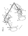
- a stabilizer bar 10 for front wheels and a stabilizer bar 12 for rear wheels.
- Each of these stabilizer bars 10, 12 is a generally U-shaped member which has torsional resilience.
- Each stabilizer bar 10, 12 consists of an intermediate rod portion 14 extending in the width or lateral direction of a vehicle, and left and right arm portions 16 and 18 which are formed integrally with the intermediate rod portion 14, so as to extend from the respective opposite longitudinal ends of the intermediate rod portion 14 in a direction almost parallel to the longitudinal direction of the vehicle.
- Lower arms 20 are provided adjacent to the respective front wheels, so as to flexibly support the front wheels, and are flexibly supported at their connecting portions 22 by respective members of the body of the vehicle.
- the stabilizer bar 10 is supported pivotably by an intermediate portion of each lower arm 20, at its connecting portions 19 which are provided at respective free ends of the left and right arm portions 16, 18 (left arm portion 16 not shown in Fig. 1) and which include respective rubber bushings or ball joints.
- the stabilizer bar 10 is also supported by suitable vehicle body members, through a hydraulic cylinder 30 at a right end section of its intermediate rod portion 14, and through a connecting rod 32 at a left end section of the intermediate rod portion1 4.
- the hydraulic cylinder 30 includes a housing 36, and a piston 38 fluid-tightly and slidably received within the housing 36 through a sealing member 37.
- the piston 38 has a piston rod 40 extending from one of its opposite surfaces.
- the piston rod 40 has, at its free end, a connecting portion 41 including a ball joint or a rubber bushing, and is attached at its connecting portion 41 to the intermediate rod portion 14 such that the piston rod 40 is pivotable about an axis of the intermediate rod portion 14 and is tiltable relative to the axis of the intermediate rod portion 14.
- the housing 36 has an connecting portion 42 at its end remote from the end through which the piston rod 40 extends, and is attached at its connecting portion 42 to a member of the vehicle body such that the housing 36 is pivotable and tiltable at the connecting portion 42 relative to the vehicle body member.
- the hydraulic cylinder 30 is interposed between the intermediate rod portion 14 and the vehicle body such that the piston rod 40 extends in the vertical direction and is connected to the intermediate rod portion 14.
- the connecting rod 32 has a connecting portion at one end thereof, and is attached at this connecting portion to the intermediate rod portion 14 such that the connecting rod 32 is pivotable about the axis of the intermediate rod portion 14 and is tiltable relative to the axis of the intermediate rod portion 14.
- the connecting rod 32 has another connecting portion at the other end, and is connected at this connecting portion to a member of the vehicle body such that the connecting rod 32 is pivotable and tiltable relative to the vehicle body member.
- the stabilizer bar 14 for the rear wheels is attached to a rear axle housing 50, at its connecting portions 48 which provided at respective free ends of the left and right arm portions 16, 18 and which include respective ball joints or rubber bushings.
- the stabilizer bar 14 is pivotable about an axis of the rear axle housing 50 and tiltable relative to the axis of the rear axle housing 50.
- the rear axle housing 50 accommodates rear axles which transmit a drive torque of a drive power source (not shown) of the vehicle to rear left and right drive wheels 54 through a differential 52.
- the stabilizer bar 12 is also supported by suitable vehicle body members, through a hydraulic cylinder 60 at a right end section of its intermediate rod portion 14, and through a connecting rod 32 at a left end section of the intermediate rod portion1 4.
- the hydraulic cylinder 60 includes a housing 66, and a piston 68 fluid-tightly and slidably received within the housing 66 through a sealing member 67.
- the piston 68 has a piston rod 70 which has a connecting portion 71a at its free end, while the housing 77 has a connecting portion 71b at its end remote from the end through which the piston rod 70 extends.
- the hydraulic cylinder 60 is connected at its connecting portion 71a to the stabilizer bar 12, and at its connecting portion 71b to a member of the vehicle body, such that the hydraulic cylinder 60 extends in the vertical direction.
- the stabilizer bars 10, 12 for the respective front-wheel and rear-wheel suspension systems of the vehicle are provided, at the right-side end sections of the intermediate rod portions 14, with the respective hydraulic cylinders 30, 60, such that the piston rods 40, 70 extend in the vertical direction and are connected to the respective stabilizer bars 10, 12.
- These two hydraulic cylinders 30, 60 have respective fluid chambers connected to each other by a fluid passage 72, and respective fluid chambers connected to each other by a fluid passage 74.
- a hydraulic circuit 76 is constituted by the hydraulic cylinders 30, 60, fluid passages 72, 74 and other components.
- the fluid passage 72 connects the fluid chambers 80, 82 of the hydraulic cylinders 30, 60, each of which is formed on one side of the piston 38, 68 which is remote from the piston rod 40, 70, while the fluid passage 72 connects the fluid chambers 84, 86 of the hydraulic cylinders 30, 60, which are formed on the piston-rod side of the piston 38, 68.
- the fluid chambers 80, 82 are the mutually corresponding two fluid chambers of the hydraulic cylinders 30, 60
- the fluid chambers 84, 86 are also the mutually corresponding two fluid chambers of the hydraulic cylinders 30, 60.
- the mutually corresponding fluid chambers 80, 82 perform the same function
- the mutually corresponding fluid chambers 84, 86 perform the same function.
- a roll motion of the vehicle body causes concurrent changes (increase or decrease) in the pressures of a working fluid in the fluid chambers 80, 82, and concurrent changes in the fluid pressure in the fluid chambers 84, 86.
- the two fluid passages 72, 74 are connected to each other by a connecting passage 88. Since the fluid chambers 80, 82 are located above the fluid chambers 84, 86, the fluid chambers 80, 82 and the fluid chambers 84, 86 will be hereinafter referred to as "upper fluid chambers 80, 82" and “lower fluid chambers 84, 86", respectively.
- a communication control unit 90 operable to control flows of the working fluid through the fluid passages 72, 74 and the connecting passage 88.
- the communication control unit 90 includes a control portion, a plurality of valves A-E, and accumulators.
- the fluid passages 72, 74 are provided with the respective valves A and B in the form of solenoid-operated shut-off valves 100, 102, which are normally-open valves that are held in their open state while their solenoid coils are placed in their de-energized state
- the connecting passage 88 is provided with the valve C in the form of a solenoid-operated shut-off valve 104, which is a normally-closed valve that is held in its closed state while its solenoid coil is placed in its de-energized state.
- the fluid passages 72, 74 are further provided with the respective accumulators 106, 108, which function to accommodate the working fluid when the fluid pressures in the fluid passages 72, 74 become higher than a predetermined upper limit, and to deliver the stored pressurized fluid to the respective fluid passages 72, 74 when the fluid pressures in the fluid passages 72, 74 become lower than a predetermined lower limit.
- each of the accumulators 106, 108 is connected to a portion of the corresponding fluid passage 72, 74 which is located between the corresponding shut-off valve 100, 102 and the rear-wheel-side end of the fluid passage 72, 74.
- valves D and E in the form of solenoid-operated shut-off valves 110, 112 are disposed between the respective accumulators 106, 108 and the corresponding fluid passages 72, 74.
- the solenoid-operated shut-off valves 110, 112 are normally-open valves that are held in their open state while their solenoid coils are placed in their de-energized state.
- the communication control unit 90 further includes pressure sensors 114 116.
- the pressure sensor 114 is connected to the fluid passage 72, while the pressure sensor 116 is connected to the fluid passage 74.
- the pressure sensors 114, 116 respectively detect the fluid pressure in the upper fluid chambers 80, 82 and the fluid pressure in the lower fluid chambers 84, 86, when the shut-off valves 100, 102 and 104 are placed in the states indicated in Fig. 2.
- the communication control unit 90 further includes a control portion 130 which is principally constituted by a computer. As indicated in Fig. 3, the control portion 130 incorporates a CPU 132, a ROM 134, a RAM 137, and an input/output portion 138. To the input/output portion 138, there are connected the above-described pressure sensors 114, 116, a roll-motion obtaining device 140, and other elements.
- the roll-motion obtaining device 140 includes a lateral acceleration sensor 142 operable to detect an acceleration value of the vehicle in its lateral direction.
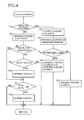
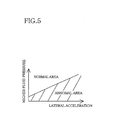
- the ROM 134 stores a valve control program illustrated in the flow chart of Fig. 4, a data table indicated in the graph of Fig. 5, etc.
- the alarming device 152 may include a light, an audio output device, or a display device, so that the alarming device 152 informs the operator of the vehicle of any abnormality, by illumination or flickering of the light, a voice message or a display.
- shut-off valves 100, 102, 104, 110, 112 are placed in the original states indicated.
- the fluid pressures detected by the pressure sensors 110 and 112 are substantially held at predetermined values Pc, Pd, respectively.
- the fluid pressure Pc in the upper fluid chambers 80, 82 detected by the pressure sensor 114 is lower than the fluid pressure Pd in the lower fluid chambers 84, 86 detected by the pressure sensor 116. That is, an effective pressure-receiving surface area of the piston 38, 68 which partially defines the upper fluid chamber 80, 82 is larger than that which partially defines the lower fluid chamber 84, 86, so that the fluid pressure in the lower fluid chambers 84, 86 is higher than that in the upper fluid chambers 80, 82 during a straight running of the vehicle (without application of an external added force to the piston 38, 68).
- each hydraulic cylinder 30, 60 The piston 38, 68 of each hydraulic cylinder 30, 60 is held at a position of equilibrium at which two forces acting on the piston 38, 68 in the respective opposite directions are equal to each other, so that the vehicle body is held substantially horizontal, without any torsion of the stabilizer bars 10, 12.
- the solenoid-operated shut-off valves 100, 102 are placed in their open state, and the solenoid-operated shut-off valves 104, 110, 112 (valves C, D and E) are placed in their closed state.
- the vehicle body While the vehicle is turning right, the vehicle body is inclined due to a centrifugal force such that the vehicle body has a lower level or height on the outer side of a turning path, namely, on the left side of the vehicle.
- the fluid pressure in the upper fluid chambers 80, 82 of the hydraulic cylinders 30, 60 is lowered, while the fluid pressure in the lower fluid chambers 84, 86 is raised.
- the fluid pressures in the upper fluid chambers 80, 82 are substantially equal to each other while the fluid pressures in the lower fluid chambers 84, 86 are substantially equal to each other, so that that an inclination of the turning vehicle body causes substantially no flows of the fluid between the upper fluid chambers 80, 82, and no flows of the fluid between the lower fluid chambers 84, 86.
- each stabilizer bar 10, 12 The inclination of the intermediate rod portions 14 of each stabilizer bar 10, 12 is restricted, and the stabilizer bars 10, 12 are subjected to torsional loads, with a result of generation of torsional resilient forces, namely, restoring forces which act on the vehicle body and the left wheels in opposite direction directions away from each other, and restoring forces which act on the vehicle body and the right wheels in opposite directions toward each other, whereby the angle of inclination of the vehicle body during the right turning of the vehicle is restricted.
- torsional resilient forces namely, restoring forces which act on the vehicle body and the left wheels in opposite direction directions away from each other, and restoring forces which act on the vehicle body and the right wheels in opposite directions toward each other
- a difference between the fluid pressure in the upper fluid chambers 80 82 and the fluid pressure in the lower fluid chambers 84, 85 during the right turning of the vehicle increases with an increase in the forces acting on the pistons 38, 68 of the hydraulic cylinders 30, 60.
- the fluid pressure difference increases with an increase in the centrifugal force acting on the turning vehicle body.
- the fluid pressure difference has a known relationship with the centrifugal force.
- the fluid pressure in the upper fluid chambers 80, 82 and the fluid pressure in the lower fluid chambers 84, 86 have a substantially constant relationship with each other.
- the centrifugal force (a force causing an inclination of the vehicle body) has a substantially constant relationship with the fluid pressure in the upper fluid chambers 80, 82 or the fluid pressure in the lower fluid chambers 84, 86.
- the control portion stores a data table representative of a predetermined relationship between the lateral acceleration value detected as a quantity relating to the centrifugal force and the higher one of the fluid pressures in the fluid passages 72, 74.
- the vehicle body While the vehicle is turning left, the vehicle body is inclined due to a centrifugal force such that the vehicle body has a lower level or height on the outer side of a turning path, namely, on the right side of the vehicle.
- the fluid pressure in the lower fluid chambers 84, 86 of the hydraulic cylinders 30, 60 is lowered, while the fluid pressure in the upper fluid chambers 80, 82 is raised.
- the fluid flows through the fluid passages 72, 74 are restricted, and the distance of vertical movement of the piston 38, 68 is limited, so that the stabilizer bars 10, 12 are subjected to torsional loads, with a result of generation of torsional resilient forces.
- the present embodiment is arranged to detect a rolling state of the vehicle during turning of the vehicle, in which each hydraulic cylinder 30, 60 has a fluid pressure difference.
- the higher one of the fluid pressures in the fluid passages 72, 74 is lower than a lower limit determined by the detected lateral acceleration value during turning of the vehicle, it is possible to estimate or determine that at least one of the fluid passages 72, 74 and the hydraulic cylinders 30, 60 suffers from a leakage of the fluid.
- both of the solenoid-operated shut-off valves 100, 102 are switched to the closed state, so that the one of the hydraulic cylinders 30, 60 which suffer from the fluid leakage, or a portion of the fluid passage 72, 74 which is located between one of the hydraulic cylinders 30, 60 and which suffers from the fluid leakage, is disconnected or shut off from the other hydraulic cylinder 30, 60, whereby the hydraulic circuit 78 is separated into two parts.
- a fluid pressure difference may arise between the two fluid chambers 80, 82, or 84, 86 on the opposite sides of the piston of the above-indicated other hydraulic cylinder 30, 60, so that one of the stabilizer bar 10 for the front wheels and the stabilizer bar 12 for the rear wheels can normally generate a torsional resilient force which restricts or limits an angle of inclination of the vehicle body.
- a normal roll-motion restricting function of either one of the two cylinders 30, 60 permits significant reduction of the deterioration of an overall roll-motion restricting function of the suspension system, as compared with the degree of deterioration where both of the two hydraulic cylinders 30, 60 were disabled to perform their normal roll-motion restricting functions.
- the fluid pressure in the lower fluid chamber 84 of the hydraulic cylinder 30 located relatively close to the front right wheel is lowered while the fluid pressure in the lower fluid chamber 86 of the hydraulic cylinder 60 located relatively close to the rear right wheel is raised, and the fluid pressure in the upper fluid chamber 82 of the hydraulic cylinder 30 is raised while the fluid pressure in the upper fluid chamber 86 of the hydraulic cylinder 60 is lowered.
- the fluid is permitted to flow through the fluid passages 72, 74 while the shut-off valves 100, 102 are held in the open state, permitting free inclination of the stabilizer bars 10, 12 without torsional deformation.
- the upper fluid chambers and the lower fluid chambers, that is, the fluid passages 72, 74 have the predetermined fluid pressures, as described above.
- the fluid may leak from a higher-pressure one of the upper and lower fluid chambers 80, 84 of the hydraulic cylinder 30 to the other fluid chamber 80, 84, and from a higher-pressure one of the upper and lower fluid chambers 82, 86 of the hydraulic cylinder 60 to the other fluid chamber 82, 86, through a gap between the sealing member 37, 67 and the inner housing surface, when there arises a considerably large fluid pressure difference between the upper and lower fluid chambers 80, 84 or between the upper and lower fluid chambers 82, 86, or when the sealing member 37, 67 is defective.
- the present embodiment is arranged to open the solenoid-operated shut-off valve 104 when the fluid pressure in the fluid passage 74 is higher by more than a predetermined amount than the fluid pressure in the fluid passage 72, during straight running of the vehicle, that is, while it is estimated that the vehicle body has a substantially horizontal attitude.
- the shut-off valve 104 is opened so that the fluid pressures in the fluid passages 72, 74 become equal to the predetermined nominal values Pc, Pd.
- step S1 A determination as to whether the vehicle is turning or not is made in step S1 (abbreviated as S1, the abbreviation applying to the other steps).
- this determination in S1 is made by determining whether the lateral acceleration value of the vehicle detected by the lateral acceleration sensor 146 is higher than a predetermined threshold value Gs.
- the threshold value Gs which may be a comparatively small value, is determined to permit the determination as to whether the vehicle is turning or running straight.
- the control flow goes to S2 to close the solenoid-operated shut-off valves 104, 110 and 112 (valves C, D and E).
- S3 is implemented to read the fluid pressures detected by the pressure sensors 114, 116, and S3 is implemented to determine whether a relationship between the detected lateral acceleration value G and the higher one of the detected fluid pressures lies in a predetermined normal or abnormal area represented by the data table of Fig. 5. If the relationship lies in the predetermined normal area, a negative decision (NO) is obtained in S4, and the control flow goes to S5 to open the solenoid-operated shut-off valves 100, 102 (valves A and B).
- the alarming device 152 is activated to inform the vehicle operator that the relationship is abnormal.
- a negative decision is obtained in S8, and the control flow goes to step S9 to determine whether an absolute value
- an abnormality of the suspension system is detected on the basis of the relationship between the lateral acceleration value G and the fluid pressure in the fluid passage 72, 74.
- the suspension system may be diagnosed on the basis of a relationship between the fluid pressure and a yaw rate of the vehicle body, a relationship between the fluid pressure and a steering angle of the vehicle, or a relationship between the fluid pressure and an attitude of the vehicle body.
- the attitude of the vehicle body may be obtained on the basis of outputs of height sensors disposed at respective positions corresponding to the respective wheels. It is noted that a rate of change of the vehicle body attitude and an acceleration value of the change may be obtained on the basis of a first derivative and a second derivative of the output of each height sensor.
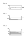
- the roll-motion obtaining device 140 includes vehicle height sensors 152 corresponding to the respective wheels, as shown in Fig. 6, a yaw rate sensor 154 as shown in Fig. 7, or a steering angle sensor 156 and a vehicle speed sensor 158 as shown in Fig. 8.
- the steering angle sensor 156 is arranged to detect a steering angle of a steering wheel of the vehicle.
- the roll-motion obtaining device 140 may include only the steering angle sensor 156, or a roll rate sensor for detecting a roll rate of the vehicle body, or a roll value sensor for detecting a roll value (roll angle) of the vehicle body.
- the roll-motion obtaining device 140 may include a plurality of sensors as indicated above. The roll value can be obtained by integrating the roll rate, and an acceleration value of the roll motion can be obtained by differentiating the roll rate.
- the memory portion of the control portion 130 stores the selected relationship, for example, a relationship between the yaw rate y and the fluid pressure, a relationship between the steering angle of the steering wheel or the steering angle of the front or rear wheels and the fluid pressure, or a relationship between the vehicle body attitude and the fluid pressure. It is noted that the centrifugal force and therefore the fluid pressure increase with an increase in the steering angle ⁇ of the steering wheel or the steering angle of the front or rear wheels (a decrease in the turning radius of the vehicle) and with an increase in the running speed of the vehicle.
- the attitude of the vehicle body during running of the vehicle may be estimated on the basis of the steering angle of the steering wheel, the steering angle of the front wheels, or the yaw rate, as described above, and the attitude while the vehicle is stationary may be estimated on the basis of the outputs of the vehicle height sensors 152 disposed at the respective positions corresponding to the wheels.
- the determination as to whether the vehicle is turning or running straight may be made on the basis of the yaw rate, the steering angle of the steering wheel, or the steering angle of the front or rear wheels.
- the suspension system may be diagnosed on the basis of a relationship between the lateral acceleration value G and a difference between the fluid pressures in the two fluid passages 72, 74.
- the diagnosis may be effected on the basis of a relationship between this fluid pressure difference and any one of the yaw rate, steering angle, roll-related parameters, etc. which have been described.
- the solenoid-operated shut-off valve 104 may be opened when it is determined on the basis of the outputs of the vehicle height sensors 152 that the fluid pressure difference of the fluid passages 72, 74 is equal to or larger than a predetermined value (that the vehicle body does not have a horizontal attitude) during straight running of the vehicle.
- the fluid pressures in the upper and lower chambers on the opposite sides of the piston 38, 68 can be considered almost equal to each other when the vehicle body is substantially horizontal.
- the solenoid-operated shut-off valve 104 may be held open while the vehicle is running straight.
- the shut-off valve 104 may be a normally-open valve.
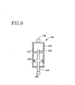
- Each of the hydraulic cylinders may be replaced by a hydraulic cylinder provided with a piston having two piston rods extending in the opposite directions.
- a hydraulic cylinder 180 which includes a housing 182, and a piston 184 which is fluid-tightly and slidably received within the housing 182 and which has two piston rods 186, 188 extending therefrom in the respective opposite directions.
- the piston rod 186 extends through the housing 182, and is connected at its connecting portion 190 to the stabilizer bar.
- the piston rod 188 fluid-tightly and slidably extends through a guiding portion 192 formed within the housing 182, but does not extends through the housing 182.
- the housing 182 has a connecting portion 194 to be fixed to a member of the vehicle body.
- the stabilizer bar 10 for the front wheels and the stabilizer bar 12 for the rear wheels may be connected in the same manner, to the vehicle body. Further, the hydraulic cylinders may be disposed so as to extend in the horizontal direction, rather than in the vertical direction. In any case, the orientation of the hydraulic cylinders is determined by the relative position between the stabilizer bars 10, 12 and the vehicle body members by which the stabilizer bars are supported, and the corresponding two fluid chambers of one pair of the two hydraulic cylinders are connected to each other by one fluid passage, while the corresponding two fluid chambers of another pair of the two hydraulic cylinders are connected toe ach other by another fluid passage.
- valves A-E used in the above-described embodiment are solenoid-operated shut-off valves which are opened and closed by application and removal of an electric current
- at least one of the valves A-E may be replaced by a solenoid-operated control valve capable of controlling a fluid pressure difference on the opposite sides thereof according to a controlled amount of electric current applied thereto.
- Each of the valves A-E may be arranged as desired, provided it is operable between an open state and a closed state for respectively permitting and inhibiting a fluid flow therethrough.
- valves A-C (solenoid-operated shut-off valves 100, 102, 104) need not be a solenoid-operated valve.
- the solenoid-operated shut-off valves 100, 102 may be replaced by pilot-operated valves which are operated according to a difference between the fluid pressures in the fluid passages 72, 74, such that the pilot-operated valves are held open while the fluid pressure difference is equal to or higher than a predetermined value.
- pilot-operated valves may be normally-closed or normally-open valves.
- a pressure sensor may be disposed between the accumulator 106 and the solenoid-operated shut-off valve 110 (valve D), and between the accumulator 108 and the solenoid-operated shut-off valve 112 (valve E).
- some amounts of fluid flow may take place between the accumulators 106, 108 and the fluid passages 72, 74 due to variations in the fluid pressures in the fluid passages during turning of the vehicle, and the pistons 38, 68 may be more or less moved in the hydraulic cylinders 30, 60.
- the distances of movements of the pistons 38, 68 are substantially equal to each other and comparatively small, however, the angles of inclination of the intermediate rod portions 14 of the stabilizer bars 10, 12 are restricted, so that the stabilizer bars are subject to torsional loads, and generate torsional resilient forces.
- the accumulators 106, 108 are connected to portions of the fluid passages 72, 74 which are located on the rear-wheel side of the solenoid-operated shut-off valves 100, 102.
- additional accumulators may be connected to portions of the fluid passages 72, 74 which are located on the front-wheel side of the solenoid-operated shut-off valves 100, 102.
- the provision of the front-wheel-side accumulators makes it possible to prevent application of an excessive force to the piston 38 of the front-wheel-side hydraulic cylinder 30 when the solenoid-operated shut-off valves 100, 102 are placed in the closed state. Further, the provision of the accumulators 106, 108 is not essential.
- the roll-motion restricting device of the vehicular suspension system is operated with a hydraulic pressure
- the roll-motion restricting device may be operated with a highly compressible gas (e.g., highly pressurized air).
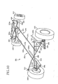
- the present vehicular suspension system is not provided with stabilizer bars, and includes a roll-motion restricting device. While the suspension system include a large number of elements, those elements which do not relate to the present invention will not be described.
- hydraulic cylinders 210, 212 corresponding to respective front right and left wheels 200, 202 are disposed between respective suspension arms in the form of lower arms 204, 206 and respective vehicle body members.
- the lower arms 204, 207 are flexibly supported at their connecting portions 214, 216 by the vehicle body members.
- Hydraulic cylinders 226, 228 corresponding to respective rear right and left wheels 220, 222 are disposed between an axle housing 224 and respective vehicle body members.
- Reference sign 229a denotes air chambers
- reference sign 229b denotes torsion bars.
- Each torsion bar 229b is connected at one end thereof to the above-described connecting portion 214, 216, and at the other end to a vehicle body member.
- the torsion bar 229b generates a torsional resilient force upon torsional deformation thereof, so that a roll motion of the vehicle body is restricted by the generated torsional resilient force.
- the provision of the torsion bars 229b is not essential.
- the torsion bars 229b may be disposed so as to connect the front right and left wheels, so that the torsion bars 229b function as stabilizer bars.
- the torsion bars may be provided for not only the front wheels but also the rear wheels.
- Each of these hydraulic cylinders 210, 212, 226, 228 extends in the vertical direction of the vehicle, and includes a housing 230, and a piston 236 which divides an interior space of the housing 230 into two fluid chambers 232, 234.
- the housing 230 is connected to a vehicle body member, while a piston rod of the piston 236 is connected to a wheel-side member.
- the housing 230 of the hydraulic cylinders 210, 212 corresponding to the front wheels is connected to the lower arm 204, 206, while that of the hydraulic cylinders 226, 228 corresponding to the rear wheels is connected to the axle housing 224.
- the fluid chamber partially defined by the upper surface of the piston 236 is a fluid chamber 232
- the fluid chamber partially defined by the lower surface of the piston 236 is a fluid chamber 234.
- the fluid chambers 232, 234 of the four hydraulic cylinders consist of one group of corresponding fluid chambers connected to each other and another group of corresponding fluid chambers connected to each other.
- the fluid pressures in the corresponding fluid chambers of one of the two groups are all raised, while the fluid pressures in the corresponding fluid chambers of the other group are all lowered.
- the upper fluid chambers 232 of the hydraulic cylinders 210, 226 respectively corresponding to the front and rear right wheels, and the lower fluid chambers 234 of the hydraulic cylinders 212, 228 respectively corresponding to the front and rear left wheels are the corresponding fluid chambers connected to each other by a fluid passage 250.
- the lower fluid chambers 234 of the hydraulic cylinders 210, 226 corresponding to the front and rear right wheels, and the upper fluid chambers 232 of the hydraulic cylinders 212, 228 corresponding to the front and rear left wheels are the corresponding fluid chambers connected to each other by a fluid passage 252.
- Those fluid passages 250, 252 are connected to each other by a connecting passage 254.
- the fluid passage 250 includes a first fluid passage 260 connecting the corresponding fluid chambers of the hydraulic cylinders 210, 212 corresponding to the respective front right and left wheels, a second fluid passage 264 connecting the corresponding fluid chambers of the hydraulic cylinders 226, 228 corresponding to the rear right and left wheels, and a third fluid passage 270 connecting the first and second fluid passages 260, 264.
- the fluid passage 252 includes a first fluid passage 262 connecting the corresponding fluid chambers of the hydraulic cylinders 210, 212 corresponding to the respective front right and left wheels, a second fluid passage 266 connecting the corresponding fluid chambers of the hydraulic cylinders 226, 228 corresponding to the rear right and left wheels, and a third fluid passage 272 connecting the first and second fluid passages 262, 266.
- the third fluid passages 270, 272 are provided with respective cut-off valves 272, 276, while the connecting passage 254 is provided with a communication control valve 280.
- a hydraulic circuit 281 is constituted by the hydraulic cylinders 210, 212, 226, 228, fluid passages 250, 252, 254, cut-off valves 274, 276, communication control valve 280, and other components.
- the cut-off valves 274, 276 and communication control valve 280 are solenoid-operated valves, and correspond to the valves A, B and C shown in Fig. 2.
- the valves A-C are solenoid-operated shut-off valves which are opened and closed by application and removal of an electric current to their solenoid coils.
- the communication control valve 280 has an open state and a closed state for respectively permitting and inhibiting fluid communication between the two fluid passages 250, 252.
- the fluid passages 260, 262 are provided with respective accumulators 290, 292, while the fluid passages 264, 266 are provided with respective accumulators 291, 293.
- the accumulators 290-293 permit flows of the working fluid between the accumulators and the fluid passages 250, 252, so as to prevent an excessive rise of the fluid pressures in the fluid passages 250, 252, and a drop of the fluid pressures to a negative level.
- Damper valves 294 are disposed between the respective accumulators 290-293 and the corresponding fluid passages 250, 252, while damper valves 296 are disposed at respective portions of the fluid passages 250, 252 which are relatively near the fluid chambers 234 of the hydraulic cylinders 210, 212, 226, 228.
- the damper valves 294, 296 have a flow restricting or throttling function to provide a resistance to a flow of the fluid therethrough and thereby exhibit an effect of damping a pressure pulsation of the fluid.
- the damper valves 294, 296 may have any desired arrangement, provided they have a throttling function.
- the damper valves are solenoid-operated valves having a constant or variable throttling effect.
- the damper valves in the form of the solenoid-operated valves may be solenoid-operated shut-off valves which are opened and closed by application and removal of an electric current, or solenoid-operated control valves a throttling effect (a cross section area of fluid flow) of which is controllable according to an amount of electric current applied thereto.
- Each damper valves may have a throttling function with respect to a fluid flow in only one of the opposite directions between the corresponding fluid passage 250, 252 and accumulator 290, 292 or fluid chamber 234, or with respect to fluid flows in both of the opposite directions. Additional damper valves may be disposed near the fluid chambers 232.
- the present suspension system includes a communication control unit 300.
- the communication control unit 300 includes a control portion 310 incorporating a CPU 302, a ROM 304, a RAM 306 and an input/output portion 308, and further includes the valves A, B and C, driver circuits 312, pressure sensors 320, 322, and a roll-motion obtaining device 324.
- the pressure sensors 320, 322 are connected to the respective fluid passages 250, 252.
- the roll-motion obtaining device 324 includes a lateral acceleration sensor 340.
- To the control portion 310 there are connected the communication control valve 280 (valve C) and the cut-off valves 274, 276 (valves A and B) through the respective driver circuits 312, and an alarming device 342.
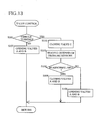
- the ROM 304 stores a data table similar to that indicated in Fig. 5, and a valve control program illustrated in the flow chart of Fig. 13.
- the fluid flows take place between the two fluid chambers of the hydraulic cylinder corresponding to that wheel, and the accumulators located near that hydraulic cylinder, namely, the accumulators 290, 292 when the wheel in question is one of the front wheels, or the accumulators 291, 293 when the wheel in question is one of the rear wheels.
- the fluid flows permit a vertical displacement of the wheel in question relative to the vehicle body. In this event, the fluid flows have a very small influence on the other wheels.
- the damper valves 294, 296 exhibit a pressure pulsation damping effect.
- the fluid flows between the corresponding two hydraulic cylinders 210, 212, or between the corresponding two hydraulic cylinders 226, 228.
- the fluid flows permit the bouncing motions of the wheels in question, without an influence on the other wheels.
- the damper valves 297 exhibit a pressure pulsation damping effect.
- the communication control valve 280 When the vehicle has a roll motion, the communication control valve 280 is placed in the closed state.
- the fluid pressures in the upper fluid chambers 232 of the two hydraulic cylinders 210, 226 on the right side of the vehicle are raised, while the fluid pressures in the lower fluid chambers 234 of the two hydraulic cylinders 212, 228 on the left side of the vehicle are also raised.
- These fluid chambers are connected to each other through the fluid passage 250.
- the fluid pressures in the other fluid chambers connected to each other through the fluid passage 252 are all lowered.
- the fluid chambers the pressures of which are raised are connected to each other through the fluid passage 250
- the fluid chambers the pressures of which are lowered are connected to each other through the fluid passage 252, while the connecting passage 254 is placed in the closed state, to prevent the fluid flows from the fluid passage 250 having a comparatively high fluid pressure into the fluid passage 252 having a comparatively low fluid pressure.
- valves A-C are controlled according to the program illustrated in the flow chart of Fig. 13, such that the suspension system is diagnosed during turning of the vehicle.
- the valve control in the present embodiment is similar to that in the preceding embodiment, except in that the valves of the present embodiment corresponding to the solenoid-operated valves 110, 112 of the preceding embodiment are not controlled.
- the two cut-off valves 274, 276 are both closed to isolate the hydraulic cylinders 210, 212 from the hydraulic cylinders 226, 228, namely, to separate the hydraulic circuit 281 into the front-wheel-side part and the rear-wheel-side part.
- This arrangement makes it possible to restrict the roll motion of the vehicle in the event of a fluid leakage occurring in one of the two parts of the hydraulic circuit 281, by enabling the other part to normally function. That is, the present arrangement reduces the degree of deterioration of the roll-motion restricting function of the hydraulic circuit, by preventing a failure of the entirety of the hydraulic circuit.
- the hydraulic circuit has an arrangement as shown in Fig. 14.
- the upper fluid chambers 232 of the hydraulic cylinders 210, 226 corresponding to the front and rear right wheels and the lower fluid chambers 234 of the hydraulic cylinders 212, 228 corresponding to the front and rear left wheels are connected to each other through a fluid passage 350
- the lower fluid chambers 234 of the hydraulic cylinders 210, 226 on the right side and the upper fluid chambers 242 of the hydraulic cylinders 212, 228 on the left side are connected to each other through a fluid passage 352.
- the fluid passages 350 and 352 are connected to each other by a connecting passage 354.
- the connecting passage 354 is provided with a communication control valve 356.
- the fluid passage 350 includes a first fluid passage 360 connecting the corresponding fluid chambers of the two hydraulic cylinders 210, 226 on the right side, a second fluid passage 364 connecting the corresponding fluid chambers of the two hydraulic cylinders 212, 228 on the left side, and a third fluid passage 368 connecting the first and second fluid passages 360, 364.
- the fluid passage 350 includes a first fluid passage 362 connecting the corresponding fluid chambers of the two hydraulic cylinders 210, 226, a second fluid passage 366 connecting the corresponding fluid passages of the two hydraulic 212, 228, and a third fluid passage 370 connecting the first and second fluid passages 362, 366.
- the fluid passages 350, 352 are provided with respective pressure sensors 372, 374, and respective accumulators 376, 378.
- a hydraulic circuit 380 is diagnosed on the basis of a relationship between the fluid pressure or pressures detected by at least one of the pressure sensors 372, 374, and the roll motion of the vehicle. It is possible to determine that a fluid leakage from the hydraulic circuit 380 takes place, if the higher one of the fluid pressures in the fluid passages 350, 352 or a difference between these fluid pressures is lower or smaller than a predetermined value corresponding to the degree of the roll motion of the vehicle, while the communication control valve 356 is placed in the closed state.
Landscapes
- Engineering & Computer Science (AREA)
- Mechanical Engineering (AREA)
- Vehicle Body Suspensions (AREA)
- Fluid-Damping Devices (AREA)
Abstract
Description
Claims (20)
- A suspension system for a vehicle, characterized by comprising:a fluid circuit including (a) at least one fluid cylinder provided on each of a front-wheel side and a rear-wheel side of the vehicle, each of said at least one fluid cylinder including a piston which separates an interior space of a housing into two fluid chambers, said each fluid cylinder being disposed between a wheel-side member of the vehicle and a body-side member of the vehicle, such that there arises a difference between fluid pressures in said two fluid chambers when at least one of a left wheel and a right wheel is displaced in a vertical direction relative to a body of the vehicle, and (b) two fluid passage systems connecting corresponding ones of the two fluid chambers of each of the fluid cylinders; anda diagnosing device operable to diagnose said fluid circuit on the basis of at least one of fluid pressures in said two fluid passage systems.
- The suspension system according to claim 1, wherein said diagnosing device comprises (a) a roll-motion-related-quantity detecting device operable to detect a roll-motion-related quantity relating to a roll motion of the vehicle, (b) a fluid-pressure detecting device operable to detect at least one of the fluid pressures in said two fluid passage systems, and (c) an abnormality determining portion operable to determine whether said fluid circuit is abnormal, on the basis of a relationship between the fluid pressure detected by said fluid-pressure detecting device and said roll-motion-related quantity detected by said roll-motion-related-quantity detecting device.
- The suspension system according to claim 2, wherein said roll-motion-related-quantity detecting device includes a centrifugal-force-related-quantity detecting device operable to detect a centrifugal-force-related quantity relating to a centrifugal force acting on the vehicle.
- The suspension system according to claim 2 or 3, wherein said roll-motion-related-quantity detecting device includes a lateral-acceleration detecting device operable to detect a lateral acceleration value of the vehicle.
- The suspension system according to any one of claims 1-4, wherein said diagnosing device includes (a) a running-condition detecting device operable to detect a running condition of the vehicle, (b) a fluid-pressure detecting device operable to detect at least one of the fluid pressures in said two fluid passage systems, and (c) an abnormality determining portion operable to determine whether said fluid circuit is abnormal, on the basis of a relationship between the fluid pressure detected by said fluid-pressure detecting device and the running condition detected by said running-condition detecting device.
- The suspension system according to any one of claims 1-5, wherein said diagnosing device includes (a) a fluid-pressure detecting device operable to detect at least one of the fluid pressures in said two fluid passage systems, and (b) an abnormality determining portion operable to determine whether said fluid circuit is abnormal, on the basis of the fluid pressure detected by said fluid-pressure detecting device.
- The suspension system according to any one of claims 1-6, further comprising a fluid-circuit separating device operable to separate said fluid circuit into two parts, when said diagnosing device determines that the fluid circuit is abnormal.
- The suspension system according to any one of claims 1-7, wherein said wheel-side member is a stabilizer bar provided on each of the front-wheel and rear-wheel sides of the vehicle, and said at least one fluid cylinder on each of the front-wheel and rear-wheel sides is disposed between said stabilizer bar and said body-side member, said two fluid passage systems consisting of two fluid passages connecting corresponding ones of the two fluid chambers of each of the at least one fluid cylinder on the front-wheel side and the at least one fluid cylinder on the rear-wheel side.
- The suspension system according to claim 8, further comprising a cut-off device operable between a state for permitting fluid flows through said two fluid passages, and a state for inhibiting the fluid flows through the two fluid passages.
- The suspension system according to claim 9, further comprising a cut-off-device control device operable to place said cut-off device in the state for inhibiting the fluid flows, when an abnormality is detected by said diagnosing device.
- The suspension system according to any one of claims 8-10, wherein said two fluid passages are provided with respective accumulators, and control valves are disposed between the respective two fluid passages and the respective accumulators.
- The suspension system according to any one of claims 1-7, wherein said at least one fluid cylinder provided on each of said front-wheel and rear-wheel sides of the vehicle consists of the two fluid cylinders disposed for said left and right wheels, respectively, between the wheel-side member and the body-side member, and said two fluid passage systems connect corresponding ones of the fluid chambers of these four fluid cylinders.
- The suspension system according to claim 12, further comprising an emergency cut-off device operable to isolate a first fluid circuit and a second fluid circuit from each other, when an abnormality of said fluid circuit is detected by said diagnosing device, said first fluid circuit including the two fluid cylinders respectively provided for one of front and rear wheels located on a right side of the vehicle and one of front and rear wheels located on a left side of the vehicle, while said second fluid circuit including the other two fluid cylinders.
- The suspension system according to claim 13, wherein said one fluid passage system includes a first fluid passage connecting the corresponding fluid chambers of the fluid cylinders respectively provided for one of the front and rear wheels located on the right side of the vehicle and one of the front and rear wheels located on the left side of the vehicle, a second fluid passage connecting the corresponding fluid chambers of the other two fluid cylinders, and a third fluid passage connecting these first and second fluid passages, and said emergency cut-off device includes a fluid-passage cut-off device operable to inhibit fluid flows through said third fluid passage.
- The suspension system according to any one of claims 1-14, wherein said fluid circuit includes (a) a connecting passage connecting said two fluid passage systems to each other, and (b) a communication control valve provided in said connecting passage, said suspension system further comprising a communication-control-valve control device operable to control said communication control valve on the basis of a running condition of the vehicle.
- The suspension system according to claim 15, wherein said communication-control-valve control device includes a fluid-pressure control portion operable to control said communication control valve for controlling a fluid pressure in each fluid chamber to a value that does not provide a roll-motion restricting effect, while the vehicle is running straight.
- A suspension system for a vehicle, characterized by comprising:a fluid circuit including (a) at least one fluid cylinder provided on each of a front-wheel side and a rear-wheel side of the vehicle, each of said at least one fluid cylinder including a piston which separates an interior space of a housing into two fluid chambers, said each fluid cylinder being disposed between a wheel-side member of the vehicle and a body-side member of the vehicle, such that there arises a difference between fluid pressures in said two fluid chambers when at least one of a left wheel and a right wheel is displaced in a vertical direction relative to a body of the vehicle, and (b) two fluid passage systems connecting corresponding ones of the two fluid chambers of each of the fluid cylinders;a separating device operable to separate said fluid circuit into two parts; anda separating-device control device operable to control said separating device on the basis of at least one of fluid pressures in said two fluid passage systems.
- The suspension system according to claim 17, wherein said separating-device control device includes (a) a fluid-pressure detecting device operable to detect at least one of the fluid pressure in said two fluid passage systems, and (b) a separating-device control portion operable to control said separating device on the basis of the at least one of the fluid pressures detected by said fluid-pressure detecting device.
- The suspension system according to claim 17 or 18, wherein said separating-device control device includes (c) a roll-motion-related-quantity detecting device operable to detect a roll-motion-related quantity relating to a roll motion of the vehicle, and (d) a roll-motion-dependent control portion operable to control said separating device on the basis of a relationship between the roll-motion-related quantity detected by said roll-motion-related-quantity detecting device and at least one of the fluid pressures in said two fluid passage systems.
- The suspension system according to any one of claims 1-19, wherein said each of said at least one fluid cylinder has two piston rods extending from said piston in respective opposite directions, and one of said two piston rods is held in engagement with said wheel-side member.
Applications Claiming Priority (1)
| Application Number | Priority Date | Filing Date | Title |
|---|---|---|---|
| PCT/JP2003/002912 WO2004080735A1 (en) | 2003-03-12 | 2003-03-12 | Suspension system for motor vehicle |
Publications (3)
| Publication Number | Publication Date |
|---|---|
| EP1602512A1 true EP1602512A1 (en) | 2005-12-07 |
| EP1602512A4 EP1602512A4 (en) | 2007-05-16 |
| EP1602512B1 EP1602512B1 (en) | 2016-04-27 |
Family
ID=32983445
Family Applications (1)
| Application Number | Title | Priority Date | Filing Date |
|---|---|---|---|
| EP03710311.6A Expired - Lifetime EP1602512B1 (en) | 2003-03-12 | 2003-03-12 | Suspension system for motor vehicle |
Country Status (6)
| Country | Link |
|---|---|
| US (1) | US7311314B2 (en) |
| EP (1) | EP1602512B1 (en) |
| JP (1) | JP3901190B2 (en) |
| CN (1) | CN1662400B (en) |
| AU (1) | AU2003221352B2 (en) |
| WO (1) | WO2004080735A1 (en) |
Cited By (1)
| Publication number | Priority date | Publication date | Assignee | Title |
|---|---|---|---|---|
| CN102350930A (en) * | 2011-07-23 | 2012-02-15 | 安庆市恒瑞达汽车零部件制造有限公司 | Hydraulic system for automotive driving stabilizer bar |
Families Citing this family (55)
| Publication number | Priority date | Publication date | Assignee | Title |
|---|---|---|---|---|
| DE10306756B4 (en) * | 2003-02-17 | 2007-01-04 | Carl Freudenberg Kg | Hydropneumatic suspension device for vehicles |
| JP4155066B2 (en) * | 2003-03-12 | 2008-09-24 | トヨタ自動車株式会社 | Vehicle suspension system |
| CN100349603C (en) * | 2005-09-28 | 2007-11-21 | 徐涛 | External medicine formulation for treating anhypnia-depression and technology for making plaster using same |
| EP1785293A1 (en) * | 2005-11-09 | 2007-05-16 | Nederlandse Organisatie Voor Toegepast-Natuurwetenschappelijk Onderzoek Tno | Hydraulic anti-roll system |
| JP4774958B2 (en) * | 2005-12-01 | 2011-09-21 | 株式会社アドヴィックス | Abnormality judgment device for vehicle motion control device |
| ATE485953T1 (en) * | 2006-01-19 | 2010-11-15 | Delphi Tech Inc | ACTIVE SUSPENSION FOR A MOTOR VEHICLE WITH CONTROL TO LIMIT THE ROLL MOTION |
| DE112008000624T5 (en) * | 2007-03-23 | 2010-01-28 | ArvinMeritor Technology, LLC, Troy | Roll control facilities |
| CN101678733B (en) * | 2007-05-30 | 2012-05-09 | 本田技研工业株式会社 | Vehicle control system and method for judging abnormality in vehicle control system |
| DE102008012906B4 (en) * | 2008-03-06 | 2009-12-17 | Zf Friedrichshafen Ag | Suspension with adjustable damping force |
| WO2010016644A1 (en) * | 2008-08-04 | 2010-02-11 | Jeong Man Hee | Device for controlling attitude of vehicle using shock absorbers |
| JP5182667B2 (en) * | 2008-09-30 | 2013-04-17 | 日立オートモティブシステムズ株式会社 | Suspension device |
| JP2010184511A (en) * | 2009-02-10 | 2010-08-26 | Aisin Seiki Co Ltd | Suspension system of vehicle |
| IT1394896B1 (en) * | 2009-06-03 | 2012-07-20 | Cometto Ind | METHOD FOR THE CONTROL OF THE SUPPLY OF AN OPERATING FLUID IN PRESSURE TO A HYDRAULIC CYLINDER OF A SUSPENSION AND VALVE GROUP TO IMPLEMENT THIS METHOD |
| JP5572485B2 (en) * | 2010-08-31 | 2014-08-13 | 日立オートモティブシステムズ株式会社 | Suspension control device |
| CN102019834A (en) * | 2010-12-10 | 2011-04-20 | 徐州重型机械有限公司 | Wheel crane and suspension hydraulic system thereof |
| CN102267353B (en) * | 2011-06-10 | 2013-06-12 | 安庆市恒瑞达汽车零部件制造有限公司 | Control system and control method for vehicular active stabilizing bar |
| DE102011056868A1 (en) * | 2011-12-22 | 2013-06-27 | Dr. Ing. H.C. F. Porsche Aktiengesellschaft | Chassis for motor car, has stabilizers firmly connected at body of motor car, so that stabilizers are not freely rotatable against body of motor car, and hydraulic position element associated with lateral end sections of each stabilizer |
| KR101351590B1 (en) * | 2012-03-13 | 2014-01-16 | 주식회사 만도 | Frequency unit valve |
| US8991832B2 (en) * | 2012-05-11 | 2015-03-31 | Doefer Companies | Double-acting suspension axle assembly for heavy load transporters |
| CN102700379B (en) * | 2012-06-07 | 2016-06-01 | 中国北方车辆研究所 | The connection hydraulic lock combination device of oil gas suspension car appearance regulation system |
| WO2014153730A1 (en) * | 2013-03-27 | 2014-10-02 | Beijingwest Industries Co., Ltd. | Hydraulic suspension system |
| JP6067455B2 (en) * | 2013-03-28 | 2017-01-25 | 株式会社ショーワ | Height adjustment device for motorcycles |
| CN103640436B (en) * | 2013-12-24 | 2017-02-15 | 重庆长安汽车股份有限公司 | Rear drive axle assembly |
| CN103863050A (en) * | 2014-03-31 | 2014-06-18 | 常州万安汽车部件科技有限公司 | Vehicle suspension system and motor vehicle |
| CA2952358A1 (en) * | 2014-06-20 | 2015-12-23 | Quadro Vehicles Sa | Improved control system of the trim of vehicles with more than two wheels |
| CN104129248B (en) * | 2014-08-11 | 2016-07-06 | 连云港天明装备有限公司 | Explosion-proof vehicle hydraulic damping device |
| JP6194902B2 (en) * | 2015-01-13 | 2017-09-13 | トヨタ自動車株式会社 | Stabilizer device |
| DE102016200930B3 (en) * | 2016-01-22 | 2017-05-04 | Ford Global Technologies, Llc | Fallback mode for Active Roll Control systems |
| CN108621737B (en) * | 2017-03-22 | 2023-08-18 | 宇通客车股份有限公司 | Automobile and hydraulic control transverse stabilizer bar device thereof |
| CN109703314A (en) * | 2017-10-26 | 2019-05-03 | 郑州宇通客车股份有限公司 | The vehicle and its suspension system that anti-side is turned over |
| JP7147528B2 (en) * | 2018-12-11 | 2022-10-05 | トヨタ自動車株式会社 | Stabilizer device and stabilizer system including the same |
| CN109703633A (en) * | 2019-02-22 | 2019-05-03 | 黄德华 | Anti-rollover system for automobiles |
| CN110789285B (en) * | 2019-12-06 | 2025-01-14 | 徐工集团工程机械股份有限公司 | Oil-gas suspension device for remote-controlled vehicle, control method and remote-controlled vehicle |
| DE102019133491A1 (en) * | 2019-12-09 | 2021-06-10 | Liebherr-Components Kirchdorf GmbH | Device and method for leak detection in a hydraulic cylinder |
| CN111674219A (en) * | 2020-04-28 | 2020-09-18 | 浙江工业大学 | An autonomous mode switching type oil-gas hybrid interconnected suspension system |
| JP7354936B2 (en) | 2020-06-09 | 2023-10-03 | トヨタ自動車株式会社 | Vehicle stabilizer system |
| GB2597454B (en) * | 2020-07-21 | 2023-01-25 | Jaguar Land Rover Ltd | Active suspension system |
| GB2597455B (en) * | 2020-07-21 | 2023-04-26 | Jaguar Land Rover Ltd | Active suspension system |
| CN214295464U (en) * | 2020-12-24 | 2021-09-28 | 临工集团济南重机有限公司 | A kind of oil and gas balance suspension system and vehicle |
| CN112757858B (en) * | 2021-01-21 | 2022-05-03 | 西安科技大学 | Vehicle electro-hydraulic energy feedback type interconnected suspension system and control method thereof |
| CN113638997B (en) * | 2021-07-21 | 2023-06-27 | 浙江工业大学 | Active and passive mode integrated intelligent oil-gas vibration reduction system |
| US11865889B2 (en) | 2021-10-12 | 2024-01-09 | DRiV Automotive Inc. | Suspension system with comfort valves between cross-over hydraulic circuits |
| US12059937B2 (en) | 2021-10-12 | 2024-08-13 | DRiV Automotive Inc. | Suspension system with roll and pitch stiffness deactivation based on road profile information |
| US12168378B2 (en) | 2021-10-12 | 2024-12-17 | DRiV Automotive Inc. | Accumulator check systems and methods |
| US11919355B2 (en) | 2021-10-12 | 2024-03-05 | DRiV Automotive Inc. | Valve diagnostic systems and methods |
| US11685220B2 (en) | 2021-10-12 | 2023-06-27 | DRiV Automotive Inc. | Control systems and methods for suspension systems |
| US11697319B2 (en) | 2021-10-12 | 2023-07-11 | DRiV Automotive Inc. | Suspension system with comfort valve integration |
| US12097739B2 (en) | 2021-10-12 | 2024-09-24 | DRiV Automotive Inc. | Pump rinsing systems and methods |
| US11912092B2 (en) * | 2021-10-12 | 2024-02-27 | DRiV Automotive Inc. | Suspension leak check systems and methods |
| US11865887B2 (en) | 2021-10-12 | 2024-01-09 | DRiV Automotive Inc. | Suspension system with incremental roll and pitch stiffness control |
| US11691474B2 (en) | 2021-10-12 | 2023-07-04 | DRiV Automotive Inc. | Suspension system tank filling systems and methods |
| US11904841B2 (en) | 2021-10-12 | 2024-02-20 | DRiV Automotive Inc. | Suspension system integration with advanced driver assistance system |
| US11938772B2 (en) | 2021-10-12 | 2024-03-26 | DRiV Automotive Inc. | System for grading filling of a hydraulic suspension system |
| US12115824B2 (en) * | 2022-03-28 | 2024-10-15 | Rivian Ip Holdings, Llc | Configurable interconnected suspension system |
| US12049114B2 (en) | 2022-10-06 | 2024-07-30 | Rivian Ip Holdings, Llc | Configurable interconnected suspension system |
Family Cites Families (26)
| Publication number | Priority date | Publication date | Assignee | Title |
|---|---|---|---|---|
| GB2135020B (en) * | 1983-02-03 | 1986-08-06 | Mitsubishi Motors Corp | Vehicle suspension unit with damping and spring rate adjustable in response to suspension extension |
| JPS60169314A (en) | 1984-02-14 | 1985-09-02 | Nissan Motor Co Ltd | Stabilizer for vehicle |
| JP2530372B2 (en) * | 1989-08-28 | 1996-09-04 | トヨタ自動車株式会社 | Suspension pressure controller |
| US5090727A (en) * | 1989-09-04 | 1992-02-25 | Nissan Motor Company, Limited | Suspension control system with vehicular driving condition dependent height adjustment |
| JP2509358B2 (en) * | 1990-02-23 | 1996-06-19 | 日産自動車株式会社 | Active suspension |
| CA2112671A1 (en) * | 1991-07-02 | 1993-01-21 | Christopher B. Heyring | Vehicle suspension system |
| US5296785A (en) * | 1991-12-23 | 1994-03-22 | Ford Motor Company | Fail-safe vehicle suspension system including switched reluctance motor |
| JPH0751923A (en) * | 1993-08-12 | 1995-02-28 | Kubota Corp | Cutting method and device |
| ATE246610T1 (en) | 1994-02-25 | 2003-08-15 | Kinetic Ltd | HYDRAULIC SUSPENSION WITH INDEPENDENT CONTROL OF PITCH AND ROLL MOVEMENT |
| DE19613769C2 (en) * | 1995-04-08 | 1997-08-21 | Fichtel & Sachs Ag | Dual circuit hydraulic system for active chassis control |
| TW355699B (en) * | 1995-08-21 | 1999-04-11 | Kiectic Ltd | Vehicular suspension systems |
| JPH09123730A (en) * | 1995-10-31 | 1997-05-13 | Kayaba Ind Co Ltd | Roll control device for vehicle |
| JP3119809B2 (en) * | 1996-01-26 | 2000-12-25 | 住友電気工業株式会社 | Method and apparatus for detecting decrease in tire air pressure |
| GB9611119D0 (en) * | 1996-05-29 | 1996-07-31 | Rover Group | Motor vehicle suspension system |
| DE69731585T2 (en) * | 1996-07-15 | 2005-12-01 | Toyota Jidosha K.K., Toyota | Vehicle driving state predicting device and warning device using the device |
| CA2266888A1 (en) | 1996-10-31 | 1998-05-07 | Richard Monk | Load distribution unit for vehicle suspension system |
| ES2274551T3 (en) | 1996-12-24 | 2007-05-16 | Kinetic Limited | PASSIVE SUSPENSION SYSTEM FOR VEHICLES INCLUDING A BALANCE CONTROL MECHANISM. |
| WO1998036923A1 (en) | 1997-02-18 | 1998-08-27 | Kinetic Limited | Control arrangement for vehicle suspension system |
| AUPO625897A0 (en) | 1997-04-17 | 1997-05-15 | Kinetic Limited | Improvements to vehicle suspension systems |
| GB9812274D0 (en) * | 1998-06-09 | 1998-08-05 | Rover Group | Hydraulic control systems |
| GB2338460B (en) * | 1998-06-09 | 2001-12-12 | Rover Group | Hydraulic control systems |
| ES2282098T3 (en) * | 1999-04-12 | 2007-10-16 | Kinetic Pty. Ltd. | PASSIVE RUNNING CONTROL FOR A VEHICLE SUSPENSION SYSTEM. |
| DE60033152T2 (en) | 1999-04-12 | 2007-12-20 | Kinetic PTY. Ltd., Dunsborourgh | ACTIVE CONTROL OF THE DRIVING BEHAVIOR FOR A VEHICLE SUSPENSION SYSTEM |
| AUPQ294899A0 (en) | 1999-09-20 | 1999-10-14 | Kinetic Limited | Pressure compensation in hydraulic vehicles suspension systems |
| JP2003080917A (en) | 2001-09-13 | 2003-03-19 | Toyota Motor Corp | Stabilizer device |
| AUPR801301A0 (en) * | 2001-09-28 | 2001-10-25 | Kinetic Pty Limited | Vehicle suspension system |
-
2003
- 2003-03-12 WO PCT/JP2003/002912 patent/WO2004080735A1/en not_active Ceased
- 2003-03-12 CN CN038139316A patent/CN1662400B/en not_active Expired - Fee Related
- 2003-03-12 US US10/512,771 patent/US7311314B2/en not_active Expired - Lifetime
- 2003-03-12 AU AU2003221352A patent/AU2003221352B2/en not_active Ceased
- 2003-03-12 EP EP03710311.6A patent/EP1602512B1/en not_active Expired - Lifetime
- 2003-03-12 JP JP2004569342A patent/JP3901190B2/en not_active Expired - Fee Related
Cited By (1)
| Publication number | Priority date | Publication date | Assignee | Title |
|---|---|---|---|---|
| CN102350930A (en) * | 2011-07-23 | 2012-02-15 | 安庆市恒瑞达汽车零部件制造有限公司 | Hydraulic system for automotive driving stabilizer bar |
Also Published As
| Publication number | Publication date |
|---|---|
| US7311314B2 (en) | 2007-12-25 |
| AU2003221352A1 (en) | 2004-09-30 |
| US20050225048A1 (en) | 2005-10-13 |
| WO2004080735A8 (en) | 2005-03-17 |
| JPWO2004080735A1 (en) | 2006-06-08 |
| CN1662400B (en) | 2011-11-16 |
| WO2004080735A1 (en) | 2004-09-23 |
| JP3901190B2 (en) | 2007-04-04 |
| EP1602512B1 (en) | 2016-04-27 |
| AU2003221352B2 (en) | 2006-08-17 |
| CN1662400A (en) | 2005-08-31 |
| EP1602512A4 (en) | 2007-05-16 |
Similar Documents
| Publication | Publication Date | Title |
|---|---|---|
| EP1602512B1 (en) | Suspension system for motor vehicle | |
| US5735540A (en) | Dual-circuit hydraulic system for an active vehicle suspension control system | |
| EP0818332B1 (en) | Roll control system | |
| JP3951728B2 (en) | Stabilizer device | |
| US5630623A (en) | Vehicle roll control system | |
| US6179310B1 (en) | Vehicle roll stabilizing system | |
| US7055832B2 (en) | Vehicle roll control system | |
| US6669208B1 (en) | Pressure compensation in hydraulic vehicle suspension systems | |
| EP0186202B1 (en) | Rear wheel suspension controller | |
| US20080269987A1 (en) | Semi-Active Roll Control System and Control Strategies for Semi-Active Roll Control | |
| EP1138531A1 (en) | Hydraulic anti-roll suspension system for motor vehicles | |
| JP4685847B2 (en) | Vehicle roll control system | |
| JPH0717135B2 (en) | Suspension for vehicles | |
| CN100564083C (en) | vehicle suspension system | |
| EP0217233A2 (en) | Suspension controller | |
| JP2004114876A (en) | Vehicle control device | |
| JP4581880B2 (en) | Suspension device | |
| JP3624871B2 (en) | Stabilizer device | |
| JP4747886B2 (en) | Vehicle equipped with a return-promoting cross-linked shock absorber system | |
| JP2003080917A (en) | Stabilizer device | |
| JP4552838B2 (en) | Vehicle equipped with a rear wheel cross-linked shock absorber system | |
| JP4760331B2 (en) | Vehicle equipped with a rear wheel cross-linked shock absorber system | |
| JP2007196832A (en) | Vehicle that detects oil leakage in cross-linked shock absorber system | |
| GB2315248A (en) | Roll control system | |
| GB2356609A (en) | A vehicle roll stabilising system |
Legal Events
| Date | Code | Title | Description |
|---|---|---|---|
| PUAI | Public reference made under article 153(3) epc to a published international application that has entered the european phase |
Free format text: ORIGINAL CODE: 0009012 |
|
| 17P | Request for examination filed |
Effective date: 20041222 |
|
| AK | Designated contracting states |
Kind code of ref document: A1 Designated state(s): AT BE BG CH CY CZ DE DK EE ES FI FR GB GR HU IE IT LI LU MC NL PT SE SI SK TR |
|
| AX | Request for extension of the european patent |
Extension state: AL LT LV MK |
|
| DAX | Request for extension of the european patent (deleted) | ||
| RBV | Designated contracting states (corrected) |
Designated state(s): DE ES FR GB IT |
|
| A4 | Supplementary search report drawn up and despatched |
Effective date: 20070418 |
|
| RIC1 | Information provided on ipc code assigned before grant |
Ipc: B60G 21/10 20060101ALI20070411BHEP Ipc: B60G 17/015 20060101AFI20070411BHEP |
|
| 17Q | First examination report despatched |
Effective date: 20121002 |
|
| RAP1 | Party data changed (applicant data changed or rights of an application transferred) |
Owner name: TOYOTA JIDOSHA KABUSHIKI KAISHA |
|
| REG | Reference to a national code |
Ref country code: DE Ref legal event code: R079 Ref document number: 60348877 Country of ref document: DE Free format text: PREVIOUS MAIN CLASS: B60G0017015000 Ipc: B60G0021067000 |
|
| GRAP | Despatch of communication of intention to grant a patent |
Free format text: ORIGINAL CODE: EPIDOSNIGR1 |
|
| RIC1 | Information provided on ipc code assigned before grant |
Ipc: B60G 17/016 20060101ALI20151027BHEP Ipc: B60G 21/10 20060101ALI20151027BHEP Ipc: B60G 21/067 20060101AFI20151027BHEP Ipc: B60G 21/055 20060101ALI20151027BHEP Ipc: B60G 17/056 20060101ALI20151027BHEP Ipc: B60G 17/0185 20060101ALI20151027BHEP |
|
| INTG | Intention to grant announced |
Effective date: 20151117 |
|
| RIN1 | Information on inventor provided before grant (corrected) |
Inventor name: KASAMATSU, AKIRA |
|
| GRAS | Grant fee paid |
Free format text: ORIGINAL CODE: EPIDOSNIGR3 |
|
| GRAA | (expected) grant |
Free format text: ORIGINAL CODE: 0009210 |
|
| AK | Designated contracting states |
Kind code of ref document: B1 Designated state(s): DE ES FR GB IT |
|
| REG | Reference to a national code |
Ref country code: GB Ref legal event code: FG4D |
|
| REG | Reference to a national code |
Ref country code: DE Ref legal event code: R096 Ref document number: 60348877 Country of ref document: DE |
|
| PG25 | Lapsed in a contracting state [announced via postgrant information from national office to epo] |
Ref country code: ES Free format text: LAPSE BECAUSE OF FAILURE TO SUBMIT A TRANSLATION OF THE DESCRIPTION OR TO PAY THE FEE WITHIN THE PRESCRIBED TIME-LIMIT Effective date: 20160427 |
|
| REG | Reference to a national code |
Ref country code: DE Ref legal event code: R084 Ref document number: 60348877 Country of ref document: DE |
|
| PG25 | Lapsed in a contracting state [announced via postgrant information from national office to epo] |
Ref country code: IT Free format text: LAPSE BECAUSE OF FAILURE TO SUBMIT A TRANSLATION OF THE DESCRIPTION OR TO PAY THE FEE WITHIN THE PRESCRIBED TIME-LIMIT Effective date: 20160427 |
|
| REG | Reference to a national code |
Ref country code: DE Ref legal event code: R097 Ref document number: 60348877 Country of ref document: DE |
|
| PLBE | No opposition filed within time limit |
Free format text: ORIGINAL CODE: 0009261 |
|
| STAA | Information on the status of an ep patent application or granted ep patent |
Free format text: STATUS: NO OPPOSITION FILED WITHIN TIME LIMIT |
|
| 26N | No opposition filed |
Effective date: 20170130 |
|
| GBPC | Gb: european patent ceased through non-payment of renewal fee |
Effective date: 20170312 |
|
| REG | Reference to a national code |
Ref country code: FR Ref legal event code: ST Effective date: 20171130 |
|
| PG25 | Lapsed in a contracting state [announced via postgrant information from national office to epo] |
Ref country code: FR Free format text: LAPSE BECAUSE OF NON-PAYMENT OF DUE FEES Effective date: 20170331 |
|
| PG25 | Lapsed in a contracting state [announced via postgrant information from national office to epo] |
Ref country code: GB Free format text: LAPSE BECAUSE OF NON-PAYMENT OF DUE FEES Effective date: 20170312 |
|
| PGFP | Annual fee paid to national office [announced via postgrant information from national office to epo] |
Ref country code: DE Payment date: 20190226 Year of fee payment: 17 |
|
| REG | Reference to a national code |
Ref country code: DE Ref legal event code: R119 Ref document number: 60348877 Country of ref document: DE |
|
| PG25 | Lapsed in a contracting state [announced via postgrant information from national office to epo] |
Ref country code: DE Free format text: LAPSE BECAUSE OF NON-PAYMENT OF DUE FEES Effective date: 20201001 |