EP1602223B1 - Echo canceller with reduced requirement for processing power - Google Patents
Echo canceller with reduced requirement for processing power Download PDFInfo
- Publication number
- EP1602223B1 EP1602223B1 EP03770158A EP03770158A EP1602223B1 EP 1602223 B1 EP1602223 B1 EP 1602223B1 EP 03770158 A EP03770158 A EP 03770158A EP 03770158 A EP03770158 A EP 03770158A EP 1602223 B1 EP1602223 B1 EP 1602223B1
- Authority
- EP
- European Patent Office
- Prior art keywords
- signal
- echo
- sub
- audio
- filter
- Prior art date
- Legal status (The legal status is an assumption and is not a legal conclusion. Google has not performed a legal analysis and makes no representation as to the accuracy of the status listed.)
- Expired - Lifetime
Links
- 238000012545 processing Methods 0.000 title claims abstract description 37
- 230000005236 sound signal Effects 0.000 claims abstract description 32
- 238000004891 communication Methods 0.000 claims abstract description 10
- 238000000034 method Methods 0.000 claims description 34
- 238000004458 analytical method Methods 0.000 claims description 14
- 230000004044 response Effects 0.000 claims description 10
- 238000001914 filtration Methods 0.000 claims description 8
- 230000009467 reduction Effects 0.000 claims description 8
- 230000002238 attenuated effect Effects 0.000 claims description 6
- 230000001419 dependent effect Effects 0.000 claims description 3
- 238000010295 mobile communication Methods 0.000 claims 2
- 238000005070 sampling Methods 0.000 abstract description 7
- 230000003111 delayed effect Effects 0.000 abstract 1
- 230000001934 delay Effects 0.000 description 11
- 230000008569 process Effects 0.000 description 8
- 238000007792 addition Methods 0.000 description 5
- 230000005540 biological transmission Effects 0.000 description 5
- 230000008901 benefit Effects 0.000 description 4
- 238000010586 diagram Methods 0.000 description 4
- 238000004364 calculation method Methods 0.000 description 3
- 238000003786 synthesis reaction Methods 0.000 description 3
- 230000015572 biosynthetic process Effects 0.000 description 2
- 230000008859 change Effects 0.000 description 2
- 230000006870 function Effects 0.000 description 2
- 238000013178 mathematical model Methods 0.000 description 2
- 230000006978 adaptation Effects 0.000 description 1
- 230000015556 catabolic process Effects 0.000 description 1
- 230000000739 chaotic effect Effects 0.000 description 1
- 238000006731 degradation reaction Methods 0.000 description 1
- 238000011161 development Methods 0.000 description 1
- 238000002592 echocardiography Methods 0.000 description 1
- 230000010354 integration Effects 0.000 description 1
- 230000000873 masking effect Effects 0.000 description 1
- 238000012986 modification Methods 0.000 description 1
- 230000004048 modification Effects 0.000 description 1
- 238000010079 rubber tapping Methods 0.000 description 1
- 230000002194 synthesizing effect Effects 0.000 description 1
- 238000012546 transfer Methods 0.000 description 1
- 230000007704 transition Effects 0.000 description 1
Images



Classifications
-
- H—ELECTRICITY
- H04—ELECTRIC COMMUNICATION TECHNIQUE
- H04M—TELEPHONIC COMMUNICATION
- H04M9/00—Arrangements for interconnection not involving centralised switching
- H04M9/08—Two-way loud-speaking telephone systems with means for conditioning the signal, e.g. for suppressing echoes for one or both directions of traffic
- H04M9/082—Two-way loud-speaking telephone systems with means for conditioning the signal, e.g. for suppressing echoes for one or both directions of traffic using echo cancellers
Definitions
- the present invention relates to an audio communication system and method with improved acoustic characteristics, and particularly to a video conferencing system including an improved audio echo cancellation system.
- a conventional conferencing system set-up that uses loudspeakers
- two or more communication units are placed at separate sites.
- a signal transmitted from one site to another site using a conference system experiences several delays, these delays will include a transmission delay and a processing delay.
- the processing delay for video signals is considerably larger than the processing delay for the audio signals. Because the video and audio signals have to be presented simultaneously, in phase, a lip sync delay is purposefully introduced to the audio signal, in both the transmitting and receiving signal paths in order to compensate for the longer video signal delay.
- one or more microphones captures a sound wave at a site A, and transforms the sound wave into a first audio signal.
- the first audio signal is transmitted to a site B, where a television set or an amplifier and loudspeaker, reproduces the original sound wave by converting the first audio signal generated at site A into the sound wave.
- the produced sound wave at site B is captured partially by the audio capturing system at site B, converted to a second audio signal, and transmitted back to the system at site A.
- This problem of having a sound wave captured at one site, transmitted to another site, and then transmitted back to the initial site is referred to as acoustic echo. In its most severe manifestation, the acoustic echo might cause feedback sound, when the loop gain exceeds unity.
- the acoustic echo also causes the participants at both site A and site B to hear themselves, making a conversation over the conferencing system difficult, particularly if there are delays in the system set-up, as is common in video conferencing systems, especially due to the above mentioned lip sync delay.
- the acoustic echo problem is usually solved using an acoustic echo canceller, described below.
- Figure 1 shows a conventional conferencing system set-up.
- Figure 1 shows the conferencing system set-up distributed at two sites, A and B.
- the two sites are connected through a transmission channel 1300 and each site has a loudspeaker 1100 and 1200, respectively, and a microphone 1111 and 1211, respectively.
- the arrows in Figure 1 indicate the direction of propagation for an acoustic signal, usually from the microphone to the loudspeaker.
- FIG. 2 is an overall view of a video conferencing system. This system is distributed at two sites, A and B.
- a video conferencing module can be distributed at more than two sites and also the system set-up is functional when only one site has a loudspeaker.
- the video module has at site A a video capturing system 2141 that captures a video image and a video subsystem 2150 that encodes the video image.
- a sound wave is captured by an audio capturing system 2111 and an audio subsystem 2130 encodes the sound wave to the acoustic signal.
- the control system 2160 introduces additional delays to the audio signal by use of a lip sync delay 2163 so to achieve synchronization between the video and audio signals.
- the video and audio signals are mixed together in a multiplexer 2161 and the resulting signal, the audio-video signal is sent over the transmission channel 2300 to site B. Additional lipsync delay 2262 is inserted at site B.
- the audio signal presented by the audio presenting device 2221 is materialized as a sound wave at site B. Part of the sound wave presented at site B arrives to the audio capturing device 2211 either as a direct sound wave or as a reflected sound wave. Capturing the sound at site B and transmitting this sound back to site A together with the associated delays forms the echo. All delays described sums up to be considerable and therefore the quality requirements for an echo canceller in the video conferencing system are particularly high.
- Fig. 3 shows an example of an acoustic echo canceller subsystem, which may be a part of the audio system in the video conferencing system of figure 2 .
- At least one of the participant sites has the acoustic echo canceller subsystem in order to reduce the echo in the communication system.
- the acoustic echo canceller subsystem 3100 is a full band model of a digital acoustic echo canceller.
- a full band model processes a complete audio band (e.g., up to 20 kHz; for video conferencing the band is typically up to 7 kHz, in audio conferencing the band is up to 3.4 kHz) of the audio signals directly.
- the acoustic echo canceller is a stand-alone device or an integrated part in the case of the communication system.
- the acoustic echo canceller transforms the acoustic signal transmitted from site A to site B, for example, using a linear/non-linear mathematical model and then subtracts the mathematically modulated acoustic signal from the acoustic signal transmitted from site B to site A.
- the acoustic echo canceller passes the first acoustic signal 3131 from site A through the mathematical modeller of the acoustic system 3121, calculates an estimate 3133 of the echo signal, subtracts the estimated echo signal from the second audio signal 3132 captured at site B, and transmits back the second audio signal 3135, less the estimated echo to site A.
- the echo canceller subsystem of figure 3 also includes an estimation error, i.e., a difference between the estimated echo and the actual echo, to update or adapt the mathematical model to a background noise and changes of the environment, at a position where the sound is captured by the audio capturing device.
- an estimation error i.e., a difference between the estimated echo and the actual echo
- the model of the acoustic system 3121 used in most echo cancellers is a FIR (Finite Impulse Response) filter, approximating the transfer function of the direct sound and most of the reflections in the room.
- the FIR filter will preferably not, mainly due to processing power, provide echo cancellation in an infinite time after the signal was captured by the loudspeaker. Instead, it will accept that the echo after a given time, the so-called tail length, will not be cancelled, but will appear as residual echo.
- a typical value for a tail length is 0.25 sec.
- LMS Least Mean Square
- One way of reducing the processing power requirements of an echo canceller is to introduce sub-band processing, i.e. the signal is divided into bands with smaller bandwidth, which can be represented using a lower sampling frequency.
- sub-band processing i.e. the signal is divided into bands with smaller bandwidth, which can be represented using a lower sampling frequency.
- An example of such system is illustrated in fig. 4 .
- Analyse filters 4125, 4131 divides the full band signals from far end and near end, respectively, in N sub-bands.
- the echo cancellation and miscellaneous sub-band processing (typically, but not limited to non-linear processing and noise reduction) is performed in each sub-band, and thereafter a synthesize filter 5127 recreates the modified full band signals. Note that in the following complexity calculations, many minor processing blocks are omitted, as their contribution to the overall processing power requirements are small.
- the analyse filters 4125, 4131 includes a filter bank and a decimator, while the synthesize filter 5127 includes a filter bank and an interpolator.
- the full band signals have sampling frequency Fs fullband .
- K is an over sampling factor, introduced to simplify and reduce the processing power requirements of the filter bank. K is always larger than one, but most often relatively small, typically less than two.
- N the processing power requirements of the filtering can be reduced, however, for the total processing power, the overhead of the analyse and synthesize filters must be added.
- Effective methods of analyzing and synthesizing the signals are based on a transform, for example a FFT.
- the echo filtering/adaption is proportional to Fs fullband 2 . It is possible to reduce the filtering/adaption part by increasing the number of subbands, but at the expense of increased overhead for the calculations of the subband signals. Still, by using a large number of subband, i.e. using a large fast transform, it is possible to obtain a complexity which increases with Fs fullband *log 2 Fs fullband .
- a sub band acoustic echo canceller is disclosed in EP 0 443 547 A2 including:
- US 6,246,760 B1 a system adapted for a subband echo cancellation for multichannel teleconferences.
- the system takes advantage of a combined vector and an echo cancellation error signal in corresponding subband, and inputting this signal into an estimation part where a cross-correlation variation component is extracted.
- the extracted component is used as an adjustment vector to iteratively adjust the impulse response of an estimated echo path.
- the combined vector is applied to an estimated echo path formed by the adjusted value to obtain an echo replica.
- An echo cancellation error signal is calculated from the echo replica and a subband echo.
- the present invention discloses an audio echo canceller according to independent claim 1 and an echo cancellation method according to claim 17. Further details are given in the dependent claims.
- the present invention takes advantage in the fact that not all frequencies are equally important in a high frequency echo cancelling system.
- an audio echo cancellation system may advantageously be designed having:
- the present invention provides a system wherein echo cancellation and noise reduction is treated as in prior art in communication critical frequency bands, while above this limit, voice switching is preferably used to provide high fidelity speech, and at the same time avoiding echo and feedback.
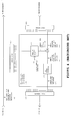
- Figure 5 shows a preferred embodiment of the present invention. It is based upon the sub-band echo cancellation system of figure 4 .
- the overall system of the preferred embodiment operates at samplerate Fs high , and the echocanceller working on samplerate Fs low , processing sound with frequencies below Fs low /2. Note that the processing box 5000 is repeated for all sub-bands.
- the signal from site B including echo, near end sound and/or noise is decimated, i.e. lowpassfiltered and downsampled by a factor n.
- the signal is also tapped and forwarded for further processing, and constitute the part of the output signal with high frequencies (above Fs low /2).
- the lowpassfiltered and downsampled signal is divided into N sub-bands by the analyse filter. Since the signal that is to be divided in the preferred embodyment of the present invention is lowpass filtered, the required magnitude of N will be reduced correspondingly.
- the sub-band signal 5132 is then added to an inverted sub-band echo estimate 5133 being generated by a (sub-)model 5121 of the acoustic system.
- the model includes preferably a FIR filter and an associated filter update algorithm, e.g. a LMS algorithm, having the corresponding sub-band signal of the audio signal from site A and a feedback loop from the result of the above-mentioned addition 5134 as inputs.
- the resulting signal 5134 is preferrably further processed by miscellaneous processing, e.g residual echo masking (due to the finite nature of the FIR filter, and any other model infirmities), noise reduction and comfort noise addition.
- the resulting signal after the miscellaneous processing will comprise the noise reduced and echo free sub-band signal from site B in addition to comfort noise.
- the above mentioned tapped signal should in some way be high pass filtered as it intends to contribute the high frequency part of the output signal. According to the present invention, this is achieved simply by subtracting the low-pass filtered signal from the original signal.
- the low pass filtered signal could be provided by tapping it right after the lowpassfilter in the decimator (delaying the mic signal by the proper amount of samples T), but this is not preferrable as it would make the decimator processing less efficient by prohibiting integration of lowpassfiltering and downsampling.
- the preferred way is to subtract the clean sub-band signal tapped right after the analyse filter from the processed sub-band signal right before the synthese filter. This will make a path in the sub-band processing part merely providing the low frequencies of the site B signal, which could be used for high pass filtering the by-passing signal by means of the already mentioned subtraction.
- the lowpass filters 5142, 5139, the downsampler 5141 and upsampler 5140 governs the highpass filter's profile, together with H s 5136 and H f 5138, which are further explained below.
- this delay must be added both before and after the filtering by H f , as H f 's magnitude must correspond to H s .
- These delays should represent the delays in the lowpass-, analysis- and synthesis-filters, as well as any additional delays.
- the present invention provides echocancelling and noisereduction at low frequencies, and unaltered microphone sound at high frequencies. This is desirable in case of near end talk, i.e. speech at site B, with a minimum of noise. However, without any level adjustments it might produce feedback, and high frequency echoes will pass right through. Feedback may even damage hearing. Hence, it is necessary to identify situations where full audible bandwidth sound is required, and situations where high frequencies should be attenuated, respectively. According to the preferred embodiment of the present invention, the control algorithm 5137 identifies these situations, typically based on (but not limited to) fullband loudspeaker and microphone signal, subband signals of the same, subband echo estimate and echo cancelled subband signal.
- the control algorithm 5137 should at least provide information determining the following situations: a) near end talk, or b) either far end talk, double talk or background noise only.
- the high frequency part of the sound should then be attenuated by adjusting the gain values of H s and H f closely to zero.
- Far end talk will produce echo, and only noise will contain high frequency components, and might trigger feedback.
- Double talk situations can be handled without high frequency sound since the ear is less sensitive to high fidelity in sound reproduction while the soundscape is chaotic as for instance when people talk at the same time.
- the decisionmaking control algorithm constantly produces values, e.g. 1 for situation a) and 0 for b), which is interpreted and used as basis for the level of high frequency sound, or more precisely, the filters H s and H f adjusting the high-pass filter's profile. This is the most important function of the filters H s and H f , namely the adjustment of the magnitude of the high frequencies.
- a highband gain change interpretation of the decision i.e. transition from a) to b) or vice versa
- H s can be reduced to time invariant gain G s while H f can be replaced by appropriate delays and a time invariant gain G f . Any change in G s must be reflected by a timely distributed changing G f . Only small errors are introduced by calculating G f as a linear interpolation of consecutive G s values.
- H s and H f In stable situations, i.e. silence (only noise) or far end talk, the gain of the filters H s and H f should stabilize at zero (no high frequency sound/noise). Near end talk will not be a very stable situation, as speech includes both sound (phrases) and silence (between phrases). Still, during phrases it is preferrable to let the gain of H s and H f (the maximum high frequency gain ) be as constant as possible and equal 1, for thereby producing full audible bandwidth sound.
- the system of the present invention may be added as a framework around existing echo cancellers, with none or only minor adjustments in the existing canceller.
- the present invention provides an efficient (in terms of development resources) way of increasing the bandwidth of existing echo canceller systems. It can be used with both sub-band and full-band echo cancellers.
- the near end signal transmitted to the far end site has not been passed through the analyse/synthesize (in the sub-band case) filter process, as the magnitude of H f is 1. Therefore, any distortion or other quality degradations in this process are not added to the near end signal.
Landscapes
- Engineering & Computer Science (AREA)
- Signal Processing (AREA)
- Cable Transmission Systems, Equalization Of Radio And Reduction Of Echo (AREA)
- Telephone Function (AREA)
- Surface Acoustic Wave Elements And Circuit Networks Thereof (AREA)
- Electrophonic Musical Instruments (AREA)
- Electrotherapy Devices (AREA)
- Telephonic Communication Services (AREA)
Abstract
Description
- The present invention relates to an audio communication system and method with improved acoustic characteristics, and particularly to a video conferencing system including an improved audio echo cancellation system.
- In a conventional conferencing system set-up that uses loudspeakers, two or more communication units are placed at separate sites. A signal transmitted from one site to another site using a conference system experiences several delays, these delays will include a transmission delay and a processing delay. For a video conferencing system, the processing delay for video signals is considerably larger than the processing delay for the audio signals. Because the video and audio signals have to be presented simultaneously, in phase, a lip sync delay is purposefully introduced to the audio signal, in both the transmitting and receiving signal paths in order to compensate for the longer video signal delay.
- In a conventional conferencing system, one or more microphones captures a sound wave at a site A, and transforms the sound wave into a first audio signal. The first audio signal is transmitted to a site B, where a television set or an amplifier and loudspeaker, reproduces the original sound wave by converting the first audio signal generated at site A into the sound wave. The produced sound wave at site B, is captured partially by the audio capturing system at site B, converted to a second audio signal, and transmitted back to the system at site A. This problem of having a sound wave captured at one site, transmitted to another site, and then transmitted back to the initial site is referred to as acoustic echo. In its most severe manifestation, the acoustic echo might cause feedback sound, when the loop gain exceeds unity. The acoustic echo also causes the participants at both site A and site B to hear themselves, making a conversation over the conferencing system difficult, particularly if there are delays in the system set-up, as is common in video conferencing systems, especially due to the above mentioned lip sync delay. The acoustic echo problem is usually solved using an acoustic echo canceller, described below.
-
Figure 1 shows a conventional conferencing system set-up. For simplicity,Figure 1 shows the conferencing system set-up distributed at two sites, A and B. The two sites are connected through atransmission channel 1300 and each site has aloudspeaker microphone 1111 and 1211, respectively. The arrows inFigure 1 indicate the direction of propagation for an acoustic signal, usually from the microphone to the loudspeaker. -
Figure 2 is an overall view of a video conferencing system. This system is distributed at two sites, A and B. As for the conferencing system set-up, a video conferencing module can be distributed at more than two sites and also the system set-up is functional when only one site has a loudspeaker. The video module has at site A a video capturingsystem 2141 that captures a video image and avideo subsystem 2150 that encodes the video image. In parallel, a sound wave is captured by an audio capturingsystem 2111 and anaudio subsystem 2130 encodes the sound wave to the acoustic signal. Due to processing delays in the video encoding system, thecontrol system 2160 introduces additional delays to the audio signal by use of alip sync delay 2163 so to achieve synchronization between the video and audio signals. The video and audio signals are mixed together in amultiplexer 2161 and the resulting signal, the audio-video signal is sent over thetransmission channel 2300 to site B.Additional lipsync delay 2262 is inserted at site B. Further, the audio signal presented by the audio presentingdevice 2221 is materialized as a sound wave at site B. Part of the sound wave presented at site B arrives to theaudio capturing device 2211 either as a direct sound wave or as a reflected sound wave. Capturing the sound at site B and transmitting this sound back to site A together with the associated delays forms the echo. All delays described sums up to be considerable and therefore the quality requirements for an echo canceller in the video conferencing system are particularly high. -
Fig. 3 shows an example of an acoustic echo canceller subsystem, which may be a part of the audio system in the video conferencing system offigure 2 . At least one of the participant sites has the acoustic echo canceller subsystem in order to reduce the echo in the communication system. The acousticecho canceller subsystem 3100 is a full band model of a digital acoustic echo canceller. A full band model processes a complete audio band (e.g., up to 20 kHz; for video conferencing the band is typically up to 7 kHz, in audio conferencing the band is up to 3.4 kHz) of the audio signals directly. - As already mentioned, compensation of acoustic echo is normally achieved by an acoustic echo canceller. The acoustic echo canceller is a stand-alone device or an integrated part in the case of the communication system.
- The acoustic echo canceller transforms the acoustic signal transmitted from site A to site B, for example, using a linear/non-linear mathematical model and then subtracts the mathematically modulated acoustic signal from the acoustic signal transmitted from site B to site A. In more detail, referring for example to the acoustic
echo canceller subsystem 3100 at site B, the acoustic echo canceller passes the firstacoustic signal 3131 from site A through the mathematical modeller of theacoustic system 3121, calculates an estimate 3133 of the echo signal, subtracts the estimated echo signal from thesecond audio signal 3132 captured at site B, and transmits back the second audio signal 3135, less the estimated echo to site A. The echo canceller subsystem offigure 3 also includes an estimation error, i.e., a difference between the estimated echo and the actual echo, to update or adapt the mathematical model to a background noise and changes of the environment, at a position where the sound is captured by the audio capturing device. - The model of the
acoustic system 3121 used in most echo cancellers is a FIR (Finite Impulse Response) filter, approximating the transfer function of the direct sound and most of the reflections in the room. The FIR filter will preferably not, mainly due to processing power, provide echo cancellation in an infinite time after the signal was captured by the loudspeaker. Instead, it will accept that the echo after a given time, the so-called tail length, will not be cancelled, but will appear as residual echo. - To estimate the echo in the complete tail length, the FIR filter will need a length L = Fs * tail length, where Fs is the sampling frequency in Hz, and where the tail length is given in seconds.
- The required number of each of the multiplications and additions to calculate one single sample output of the filter equals the filter length, and the output of the filter should be calculated once per sample. I.e. the total number of multiplications and additions are Fs*L = Fs * Fs* tail length = tail length*Fs2.
- A typical value for a tail length is 0.25 sec. The number of multiplications and additions for Fs= 8 kHz system will be 16 Millions, for 16 kHz 64 Millions and for 48 kHz 576 Millions.
- Similar calculations could be performed for the filter update algorithm. The simplest algorithm, LMS (Least Mean Square), has a complexity proportional to the filter length, which implies a processing power requirement proportional to Fs2, while more complex algorithms have processing power proportional to the square of the filter length, which implies a processing power requirement proportional to Fs3.
- One way of reducing the processing power requirements of an echo canceller is to introduce sub-band processing, i.e. the signal is divided into bands with smaller bandwidth, which can be represented using a lower sampling frequency. An example of such system is illustrated in
fig. 4 . -
Analyse filters filter 5127 recreates the modified full band signals. Note that in the following complexity calculations, many minor processing blocks are omitted, as their contribution to the overall processing power requirements are small. - The
analyse filters filter 5127 includes a filter bank and an interpolator. The full band signals have sampling frequency Fsfullband. The sub-band signals will have a sampling frequency of Fssub-band = K/N*Fsfullband. K is an over sampling factor, introduced to simplify and reduce the processing power requirements of the filter bank. K is always larger than one, but most often relatively small, typically less than two. - The processing power for the filtering and adaptation (assuming FIR and LMS) for the sub-band case is: Osub-band =c1*taillength* Fssub-band 2 = c1*tail length* (K/N*Fsfullband)2 (c1 is a proportionally constant). Thus, for a high N, the processing power requirements of the filtering can be reduced, however, for the total processing power, the overhead of the analyse and synthesize filters must be added.
- Effective methods of analyzing and synthesizing the signals are based on a transform, for example a FFT. The methods have complexity Ooverhead = c2*N* log2N, where N is the number of subbands, and c2 is a proportionally constant. The number of subbands will be proportional with Fsfullband and thus Ooverhead = C3*Fsfullband*log2 Fsfullband.
- I.e. the total complexity is:

- The echo filtering/adaption is proportional to Fsfullband 2. It is possible to reduce the filtering/adaption part by increasing the number of subbands, but at the expense of increased overhead for the calculations of the subband signals. Still, by using a large number of subband, i.e. using a large fast transform, it is possible to obtain a complexity which increases with Fsfullband*log2 Fsfullband.
- A sub band acoustic echo canceller is disclosed in
EP 0 443 547 A2 including: - A first division and decimation process part for dividing a reception signal from a line into first band signals of N channels and for decimating each of the first band signals to output decimated first band signals in a form of complex signals, where N is an integer greater than or equal to two.
- A second division and decimation process part that divides a transmission signal into second band signals of N channels that decimates each of the second band signals to output decimated second band signals in a form of complex signals.
- An echo canceller group made up of a group of echo cancellers for generating a pseudo echo in each band based on a corresponding decimated first band signals received from the first division and decimation process part by referring to a corresponding decimated second band signals received from the second division and decimation process part and for outputting a residual signal in each band by subtracting the pseudo echo of one band from the decimated second band signal of the same band, and
- an interpolation and synthesis process part for subjecting the residual signals received from the echo canceller group to interpolation and synthesis to output a synthesized residual signal which is transmitted to a line as the transmission signal, where the echo canceller group carries out an echo cancelling operation for each band in a complex signal region. Hence the this publication introduces an echo canceller group adapted to generate pseudo echo signals.
- It is furthermore known from
US 6,246,760 B1 a system adapted for a subband echo cancellation for multichannel teleconferences. The system takes advantage of a combined vector and an echo cancellation error signal in corresponding subband, and inputting this signal into an estimation part where a cross-correlation variation component is extracted. The extracted component is used as an adjustment vector to iteratively adjust the impulse response of an estimated echo path. The combined vector is applied to an estimated echo path formed by the adjusted value to obtain an echo replica. An echo cancellation error signal is calculated from the echo replica and a subband echo. - Though theoretically possible, this may be difficult to achieve in practical implementations, due to cache ineffiency in signal processing when applying large transforms.
- Thus, efforts have been made for providing a system allowing reduction in the number of sub-bands without increasing the sub-bandwidths.
- It is an object of the present invention to provide a system allowing reduction in the number of sub-bands without increasing the sub-bandwidths.
- The features defined in the independent claim enclosed characterise this system.
- The present invention discloses an audio echo canceller according to independent claim 1 and an echo cancellation method according to claim 17. Further details are given in the dependent claims.
- In order to make the invention more readily understandable, the discussion that follows will refer to the accompanying drawings,
-
Figure 1 is an overview block diagram of a conventional conferencing system set-up, -
Figure 2 is a more detailed block diagram of a conventional conferencing system set-up, -
Figure 3 is a closer view of an acoustic echo canceller subsystem, -
Figure 4 is a block diagram of the corresponding echo canceller subsystem implemented with sub-band processing, -
Figure 5 is a block diagram of an echo canceller subsystem implemented with sub-band processing according to the present invention. - In the following, the present invention will be discussed by describing a preferred embodiment, and by referring to the accompanying drawings. However, even if the specific embodiment is described in connection with video conferencing, people skilled in the art will realize other applications and modifications within the scope of the invention as defined in the enclosed independent claim.
- The present invention takes advantage in the fact that not all frequencies are equally important in a high frequency echo cancelling system.
- Frequencies above approximate 7 kHz does not contribute much to the speech intelligibility. However, these frequencies impacts on the naturalness and experienced vicinity are considerable.
- Experience has shown that both speech intelligibility and listening impression are maintained even when the returning signal at certain occurrences is being low pass filtered and down sampled. In other words, an audio echo cancellation system may advantageously be designed having:
- a) full duplex communication (including echo cancelling) in frequencies which contributes to speech intelligibility, to ensure that no information is lost during double talk, and
- b) full bandwidth and increased naturalness during periods with single talk.
- By embodying the above limitations properly, the exhaustive sampling frequency influence on the processing power requirements may be reduced, while still obtaining the benefits of full audible bandwidth sound.
- The present invention provides a system wherein echo cancellation and noise reduction is treated as in prior art in communication critical frequency bands, while above this limit, voice switching is preferably used to provide high fidelity speech, and at the same time avoiding echo and feedback.
-
Figure 5 shows a preferred embodiment of the present invention. It is based upon the sub-band echo cancellation system offigure 4 . The overall system of the preferred embodiment operates at samplerate Fshigh, and the echocanceller working on samplerate Fslow, processing sound with frequencies below Fslow /2. Note that the processing box 5000 is repeated for all sub-bands. - Before being processed by the echocanceller the signal from site B, including echo, near end sound and/or noise is decimated, i.e. lowpassfiltered and downsampled by a factor n. The signal is also tapped and forwarded for further processing, and constitute the part of the output signal with high frequencies (above Fslow /2). The lowpassfiltered and downsampled signal is divided into N sub-bands by the analyse filter. Since the signal that is to be divided in the preferred embodyment of the present invention is lowpass filtered, the required magnitude of N will be reduced correspondingly.
- The
sub-band signal 5132 is then added to an invertedsub-band echo estimate 5133 being generated by a (sub-)model 5121 of the acoustic system. As in prior art, the model includes preferably a FIR filter and an associated filter update algorithm, e.g. a LMS algorithm, having the corresponding sub-band signal of the audio signal from site A and a feedback loop from the result of the above-mentionedaddition 5134 as inputs. The resultingsignal 5134 is preferrably further processed by miscellaneous processing, e.g residual echo masking (due to the finite nature of the FIR filter, and any other model infirmities), noise reduction and comfort noise addition. The resulting signal after the miscellaneous processing will comprise the noise reduced and echo free sub-band signal from site B in addition to comfort noise. - The above mentioned tapped signal should in some way be high pass filtered as it intends to contribute the high frequency part of the output signal. According to the present invention, this is achieved simply by subtracting the low-pass filtered signal from the original signal. The low pass filtered signal could be provided by tapping it right after the lowpassfilter in the decimator (delaying the mic signal by the proper amount of samples T), but this is not preferrable as it would make the decimator processing less efficient by prohibiting integration of lowpassfiltering and downsampling. The preferred way is to subtract the clean sub-band signal tapped right after the analyse filter from the processed sub-band signal right before the synthese filter. This will make a path in the sub-band processing part merely providing the low frequencies of the site B signal, which could be used for high pass filtering the by-passing signal by means of the already mentioned subtraction.
- The lowpass filters 5142, 5139, the
downsampler 5141 andupsampler 5140 governs the highpass filter's profile, together withH s 5136 andH f 5138, which are further explained below. Having appropriate delay of the bypassing signal is of course crucial for this kind of filtering, this delay must be added both before and after the filtering by Hf, as Hf's magnitude must correspond to Hs. These delays should represent the delays in the lowpass-, analysis- and synthesis-filters, as well as any additional delays. - The present invention provides echocancelling and noisereduction at low frequencies, and unaltered microphone sound at high frequencies. This is desirable in case of near end talk, i.e. speech at site B, with a minimum of noise. However, without any level adjustments it might produce feedback, and high frequency echoes will pass right through. Feedback may even damage hearing. Hence, it is necessary to identify situations where full audible bandwidth sound is required, and situations where high frequencies should be attenuated, respectively. According to the preferred embodiment of the present invention, the
control algorithm 5137 identifies these situations, typically based on (but not limited to) fullband loudspeaker and microphone signal, subband signals of the same, subband echo estimate and echo cancelled subband signal. - The
control algorithm 5137 should at least provide information determining the following situations: a) near end talk, or b) either far end talk, double talk or background noise only. In case b), the high frequency part of the sound should then be attenuated by adjusting the gain values of Hs and Hf closely to zero. Far end talk will produce echo, and only noise will contain high frequency components, and might trigger feedback. Double talk situations can be handled without high frequency sound since the ear is less sensitive to high fidelity in sound reproduction while the soundscape is chaotic as for instance when people talk at the same time. - The decisionmaking control algorithm constantly produces values, e.g. 1 for situation a) and 0 for b), which is interpreted and used as basis for the level of high frequency sound, or more precisely, the filters Hs and Hf adjusting the high-pass filter's profile. This is the most important function of the filters Hs and Hf, namely the adjustment of the magnitude of the high frequencies. In the following an example of a highband gain change interpretation of the decision (i.e. transition from a) to b) or vice versa), is disclosed.
- Assume the sound is partitioned in packages of duration 10ms, at a samplerate of Fshigh = 48000kS/s, and n=3 so that Fslow = 16000kS/s. When the echocanceller operates on sub-bands, the decision is typically taken once a packet, so the adjustment of the filters can be done at most once each sound-packet. As the sub-band samples are representing 10ms each in a narrow frequency band, while the signal samples from site B on the other hand each represents a small amount of time in a relatively broad frequency band, it would be obvious for a man skilled in the art that the result of gain adjustments in the lower frequencies (provided by the magnitude of Hs) should be accordingly treated at high frequencies (i.e. the corresponding magnitude of Hf).
- If the decimator, analyze filter, synthesize filter and interpolator together form a linear phase system, Hs can be reduced to time invariant gain Gs while Hf can be replaced by appropriate delays and a time invariant gain Gf. Any change in Gs must be reflected by a timely distributed changing Gf. Only small errors are introduced by calculating Gf as a linear interpolation of consecutive Gs values.
- In stable situations, i.e. silence (only noise) or far end talk, the gain of the filters Hs and Hf should stabilize at zero (no high frequency sound/noise). Near end talk will not be a very stable situation, as speech includes both sound (phrases) and silence (between phrases). Still, during phrases it is preferrable to let the gain of Hs and Hf (the maximum high frequency gain ) be as constant as possible and equal 1, for thereby producing full audible bandwidth sound.
- Note that there might be cases of large amounts of background noise where a lower level of maximum high frequency gain (between 0 and 1) is preferable. The reduction of maximum high frequency gain will of course deteriorate the functionality of the device and should be solved by reducing high frequency background noise when possible.
- Even if the present invention is described in connection with videoconferencing, a person skilled in the art would realize that it would also be useful in other equivalent applications like telephone conferences and calls, mobile telephone conferences and calls, web conferences etc.
- The main advantage of the present invention is that it requires lower processing power than prior art because of fewer sub-bands. Its complexity is O = C4*Fslow*log2 Fslow + c5*Fshigh. I.e. when the bandwidth increases above the communication critical frequency bands, the complexity only scales linearly with the bandwidth.
- Further, the system of the present invention may be added as a framework around existing echo cancellers, with none or only minor adjustments in the existing canceller. Thus, the present invention provides an efficient (in terms of development resources) way of increasing the bandwidth of existing echo canceller systems. It can be used with both sub-band and full-band echo cancellers.
- In addition, improved audio quality for the near end signal during single talk may be provided. The near end signal transmitted to the far end site has not been passed through the analyse/synthesize (in the sub-band case) filter process, as the magnitude of Hf is 1. Therefore, any distortion or other quality degradations in this process are not added to the near end signal.
Claims (32)
- An audio echo canceller for providing an echo-attenuated output signal (5155) from an echo-added input signal (5152), said audio echo cancellation apparatus comprising
a first analyse filter (5126) adapted to divide a first analyse filter input signal into a number of first input sub-signals of respective frequency sub-bands; and
a processing unit (5000) adapted to generate a number of output sub-signals based on said number of first input sub-signals by generating, for each first input sub-signal (5132), a corresponding output sub-signal (5135); and
a synthesize filter (5127) adapted to combine said number of output sub-signals into one synthesize filter output signal;
wherein said processing unit comprises a module including, for each first input subsignal (5132), corresponding echo estimating means adapted to generate a corresponding echo estimate sub-signal (5133) by implementing a model of acoustic echo and corresponding subtracting means adapted to generate a corresponding echo-reduced sub-signal (5134) by subtracting said corresponding echo estimate sub-signal (5133) from said first input sub-signal (5132), said module further adapted to generate a corresponding module output sub-signal (5150) based on said corresponding echo-reduced sub-signal (5134),
said audio echo canceller characterized in that
the processing unit (5000) further comprises, for each first input sub-signal (5132), means adapted to generate a corresponding adjusted input sub-signal by applying a first filter (5136) to said first input sub-signal (5132) and means adapted to generate said corresponding output sub-signal (5135) by subtracting the corresponding adjusted input sub-signal from the corresponding module output sub-signal (5150); and
in that the audio canceller further comprises
a first decimator adapted to generate the first analyse filter input signal by applying a low-pass filter (5142) plus a down-sampler (5141) to the echo-added input signal (5152); and
an interpolator adapted to generate an interpolator output signal (5154) by applying an up-sampler (5140) plus a low-pass filter (5139) to the synthesize filter output signal; and
a second filter (5138) adapted to generate an adjusted echo-added input signal (5153) by filtering said echo-added input signal (5152); and
an adding device adapted to generate said echo-attenuated output signal (5155) by adding said adjusted echo-added input signal (5153) to said interpolator output signal (5154). - Audio echo canceller according to claim 1, characterized in that it comprises a second analyse filter (5125) adapted to divide an output of a second decimator (5123/5124) into a number of echo model input sub-signals of respective sub frequency bands and to provide corresponding echo model input sub-signals to said corresponding echo estimating means.
- Audio echo canceller according to claim 2, characterized in that it comprises a control module (5137) adapted to adjust a response of said first and second filters (5136, 5138) dependent on said input sub-signals and said corresponding echo model input sub-signals.
- Audio echo canceller according to claim 2 or 3, characterized in that the second decimator (5123/5124) include a low pass filter (5123) and a downsampler (5124).
- Audio echo canceller according to claim 4, characterized in that one or more of the low pass filters are implemented as FIR filters.
- Audio echo canceller according to claim 4 or 5, characterized in that the first analyse filter, the synthesize filter and one or more of the low pass filters are linear phase filters.
- Audio echo canceller according to claim 6, characterized in that the first and the second filters are time variant amplifiers.
- Audio echo canceller according to one of the claims 1 - 5, characterized in that the first and the second filters are amplifiers.
- Audio echo canceller according to one of the preceding claims, characterized in that it comprises one or more delay units before and/or after, or integrated in, the second filter (5138), which accumulated correspond to a delay appearing from the first decimator (5141/15142) to the interpolator (5139/5140).
- Audio echo canceller according to one of the preceding claims, characterized in that each of said corresponding echo estimating means includes a FIR filter and an associated filter update algorithm.
- Audio echo canceller according to one of the preceding claims, characterized in that said module further includes, for each input sub-signal, a corresponding miscellaneous processing unit (5122) adapted to generate a corresponding module output sub-signal (5150) by applying to said corresponding echo-reduced sub-signal (5134) at least one or more of the following: a residual echo masker, a noise reduction algorithm and a comfort noise generator.
- Audio echo canceller according to one of claims 2-11, characterized in that the audio echo canceller is a part of a video conferencing system wherein the input of the second decimator is a second audio signal (5131) captured by a microphone at a far end site including far end sound, and the echo added input signal (5152) is a first audio signal captured by a microphone at a near end site including near end sound, noise and the acoustic echo.
- Audio echo canceller according to one of the claims 2-11, characterized in that the audio echo canceller is a part of a telephone communication or conferencing system wherein the input of the second decimator is a second audio signal (5131) captured by a microphone at a far end site including far end sound, and the echo added input signal (5152) is a first audio signal captured by a microphone at a near end site including near end sound, noise and the acoustic echo.
- Audio echo canceller according to one of the claims 2 -11, characterized in that the audio echo canceller is a part of a mobile communication or conferencing system wherein the input of the second decimator is a second audio signal (5131) captured by a microphone at a far end site including far end sound, and the echo added input signal (5152) is a first audio signal captured by a microphone at a near end site including near end sound, noise and the acoustic echo.
- Audio echo canceller according to claim 12, 13 or 14 when depending on claim 3, characterized in that the control module (5137) is adapted to detect the presence and content of said first and second audio signals and to adjust said response accordingly.
- Audio echo canceller according to claim 15, characterized in that the control module (5137) is adapted to adjust the response to a first positive non-zero value, less than or equal to one, if near end sound together with noise, or near end sound only is detected, and to a second zero value in all other cases.
- A method for providing an echo-attenuated output signal (5155) from an echo-added input signal (5152), said method comprising the following steps:dividing a first analyse filter input signal into a number of first input sub-signals of respective frequency sub-bands; andgenerating a number of output sub-signals based on said number of first input subsignals by generating, for each first input sub-signal (5132), a corresponding output sub-signal (5135); andcombining said number of output sub-signals into one synthesize filter output signal;said method characterized in thatthe step of generating a number of output sub-signals comprises, for each first input sub-signal (5132), the steps of generating a corresponding echo estimate sub-signal (5133) by implementing a model of acoustic echo; and generating a corresponding echo-reduced sub-signal (5134) by subtracting said corresponding echo estimate sub-signal (5133) from said first input sub-signal (5132); and generating a corresponding module output sub-signal (5150) based on said corresponding echoreduced sub-signal (5134), andin that the method comprises the additional steps of:generating the first analyse filter input signal by applying a low-pass filter (5142) plus a down-sampler (5141) to the echo-added input signal (5152); andgenerating an interpolator output signal (5154) by applying an up-sampler (5140) plus a low-pass filter (5139) to the synthesize filter output signal; andgenerating an adjusted echo-added input signal (5153) by applying a second filter (5138) to said echo-added input signal (5152); andgenerating said echo-attenuated output signal (5155) by adding said adjusted echoadded input signal (5153) to said interpolator output signal (5154).
- Method according to claim 17, characterized in that it comprises the additional step of dividing an output of a second decimator (5123/5124) into a number of echo model input sub-signals of respective frequency sub-bands and providing corresponding echo model input sub-signals to said corresponding echo estimating means.
- Method according to claim 18, characterized in that it comprises the additional step of adjusting a response of said first and second filters (5136, 5138) dependent on said input sub-signals and said corresponding echo model input sub-signals.
- Method according to claim 18 or 19, characterized in that it comprises the additional step of generating the output of the second decimator (5123/5124) by applying a low pass filter (5123) and a downsampler (5124).
- Method according to claim 20, characterized in that one or more of the low pass filters are FIR filters.
- Method according to claim 20 or 21, characterized in that the steps of dividing a first analyse filter input signal, combining said number of output sub-signals and applying said one or more of the low pass filters are carried out by means of linear phase filters.
- Method according to claim 22, characterized in that the first and the second filters are time variant amplifiers.
- Method according to one of the claims 17 - 22, characterized in that the first and the second filters are amplifiers.
- Method according to one of the claims 17-24, characterized in that it comprises the additional step of adding one or more delay units before and/or after, or within, the second filter (5138), which accumulated correspond to a delay appearing from the first decimator (5141/5142) to the interpolator (5139/5140).
- Method according to one of the claims 17-25, characterized in that the step of generating said corresponding echo estimate sub-signal (5133) is carried out by means of a FIR filter and an associated filter update algorithm.
- Method according to one of the claims 17-26, characterized in that the step of generating a corresponding module output sub-signal (5150) includes applying to said corresponding echo-reduced sub-signal (5134) at least one or more of the following: a residual echo masker, a noise reduction algorithm and a comfort noise generator.
- Method according to one of claims 18-27, characterized in that the method is carried out within a video conferencing system wherein the input of the second decimator is a second audio signal (5131) captured by a microphone at a far end site including far end sound, and the echo added input signal (5152) is a first audio signal captured by a microphone at a near end site including near end sound, noise and the acoustic echo.
- Method according to one of the claims 18-27, characterized in that the method is carried out within a telephone communication or conferencing system wherein the input of the second decimator is a second audio signal (5131) captured by a microphone at a far end site including far end sound, and the echo added input signal (5152) is a first audio signal captured by a microphone at a near end site including near end sound, noise and the acoustic echo.
- Method according to one of the claims 18 -27, characterized in that the method is carried out within a mobile communication or conferencing system wherein the input of the second decimator is a second audio signal (5131) captured by a microphone at a far end site including far end sound, and the echo added input signal (5152) is a first audio signal captured by a microphone at a near end site including near end sound, noise and the acoustic echo.
- Method according to claims 28, 29 or 30 when depending on claim 19, characterized in that step of adjusting a response of said first and second filters (5136, 5138) includes detecting the presence and content of said first and second audio signals and adjusting said response accordingly.
- Method according to claim 31, characterized in that the step of detecting the presence and content of said first and second audio signals and adjusting said response accordingly comprises adjusting the response to a first positive non-zero value, less than or equal to one, if near end sound together with noise, or near end sound only is detected, and to a second zero value in all other cases.
Applications Claiming Priority (3)
| Application Number | Priority Date | Filing Date | Title |
|---|---|---|---|
| NO20031103 | 2003-03-10 | ||
| NO20031103A NO318401B1 (en) | 2003-03-10 | 2003-03-10 | An audio echo cancellation system and method for providing an echo muted output signal from an echo added signal |
| PCT/NO2003/000379 WO2004082249A1 (en) | 2003-03-10 | 2003-11-11 | Echo canceller with reduced requirement for processing power |
Publications (2)
| Publication Number | Publication Date |
|---|---|
| EP1602223A1 EP1602223A1 (en) | 2005-12-07 |
| EP1602223B1 true EP1602223B1 (en) | 2009-06-03 |
Family
ID=19914556
Family Applications (1)
| Application Number | Title | Priority Date | Filing Date |
|---|---|---|---|
| EP03770158A Expired - Lifetime EP1602223B1 (en) | 2003-03-10 | 2003-11-11 | Echo canceller with reduced requirement for processing power |
Country Status (10)
| Country | Link |
|---|---|
| US (1) | US7010119B2 (en) |
| EP (1) | EP1602223B1 (en) |
| JP (1) | JP2006514492A (en) |
| CN (1) | CN100521710C (en) |
| AT (1) | ATE433253T1 (en) |
| AU (1) | AU2003278623A1 (en) |
| DE (1) | DE60327895D1 (en) |
| ES (1) | ES2328032T3 (en) |
| NO (1) | NO318401B1 (en) |
| WO (1) | WO2004082249A1 (en) |
Families Citing this family (64)
| Publication number | Priority date | Publication date | Assignee | Title |
|---|---|---|---|---|
| US7433463B2 (en) * | 2004-08-10 | 2008-10-07 | Clarity Technologies, Inc. | Echo cancellation and noise reduction method |
| NO328256B1 (en) * | 2004-12-29 | 2010-01-18 | Tandberg Telecom As | Audio System |
| NO324318B1 (en) * | 2005-04-29 | 2007-09-24 | Tandberg Telecom As | Method and apparatus for noise detection. |
| TW200735624A (en) * | 2006-01-27 | 2007-09-16 | Mediatek Inc | Method and apparatus for echo cancellation |
| CN101496387B (en) | 2006-03-06 | 2012-09-05 | 思科技术公司 | System and method for access authentication in a mobile wireless network |
| US7783478B2 (en) * | 2007-01-03 | 2010-08-24 | Alexander Goldin | Two stage frequency subband decomposition |
| EP2018034B1 (en) * | 2007-07-16 | 2011-11-02 | Nuance Communications, Inc. | Method and system for processing sound signals in a vehicle multimedia system |
| ES2398597T3 (en) | 2007-11-29 | 2013-03-20 | Telefonaktiebolaget Lm Ericsson (Publ) | A method and arrangement for echo cancellation of voice signals |
| US8744069B2 (en) * | 2007-12-10 | 2014-06-03 | Microsoft Corporation | Removing near-end frequencies from far-end sound |
| US8433061B2 (en) * | 2007-12-10 | 2013-04-30 | Microsoft Corporation | Reducing echo |
| US8219387B2 (en) * | 2007-12-10 | 2012-07-10 | Microsoft Corporation | Identifying far-end sound |
| US8355041B2 (en) | 2008-02-14 | 2013-01-15 | Cisco Technology, Inc. | Telepresence system for 360 degree video conferencing |
| US8797377B2 (en) | 2008-02-14 | 2014-08-05 | Cisco Technology, Inc. | Method and system for videoconference configuration |
| GB2457986A (en) * | 2008-03-06 | 2009-09-09 | Cambridge Silicon Radio Ltd | Acoustic echo cancellation |
| US8319819B2 (en) | 2008-03-26 | 2012-11-27 | Cisco Technology, Inc. | Virtual round-table videoconference |
| US8390667B2 (en) | 2008-04-15 | 2013-03-05 | Cisco Technology, Inc. | Pop-up PIP for people not in picture |
| US8290141B2 (en) * | 2008-04-18 | 2012-10-16 | Freescale Semiconductor, Inc. | Techniques for comfort noise generation in a communication system |
| US8233629B2 (en) * | 2008-09-04 | 2012-07-31 | Dts, Inc. | Interaural time delay restoration system and method |
| US8694658B2 (en) | 2008-09-19 | 2014-04-08 | Cisco Technology, Inc. | System and method for enabling communication sessions in a network environment |
| US8659637B2 (en) | 2009-03-09 | 2014-02-25 | Cisco Technology, Inc. | System and method for providing three dimensional video conferencing in a network environment |
| US8477175B2 (en) * | 2009-03-09 | 2013-07-02 | Cisco Technology, Inc. | System and method for providing three dimensional imaging in a network environment |
| US8659639B2 (en) | 2009-05-29 | 2014-02-25 | Cisco Technology, Inc. | System and method for extending communications between participants in a conferencing environment |
| US9082297B2 (en) | 2009-08-11 | 2015-07-14 | Cisco Technology, Inc. | System and method for verifying parameters in an audiovisual environment |
| US9225916B2 (en) | 2010-03-18 | 2015-12-29 | Cisco Technology, Inc. | System and method for enhancing video images in a conferencing environment |
| US9313452B2 (en) | 2010-05-17 | 2016-04-12 | Cisco Technology, Inc. | System and method for providing retracting optics in a video conferencing environment |
| US8896655B2 (en) | 2010-08-31 | 2014-11-25 | Cisco Technology, Inc. | System and method for providing depth adaptive video conferencing |
| US8599934B2 (en) | 2010-09-08 | 2013-12-03 | Cisco Technology, Inc. | System and method for skip coding during video conferencing in a network environment |
| CN101958122B (en) * | 2010-09-19 | 2013-01-09 | 杭州华三通信技术有限公司 | Method and device for eliminating echo |
| US9042535B2 (en) | 2010-09-29 | 2015-05-26 | Cisco Technology, Inc. | Echo control optimization |
| US8599865B2 (en) | 2010-10-26 | 2013-12-03 | Cisco Technology, Inc. | System and method for provisioning flows in a mobile network environment |
| US8699457B2 (en) | 2010-11-03 | 2014-04-15 | Cisco Technology, Inc. | System and method for managing flows in a mobile network environment |
| US9143725B2 (en) | 2010-11-15 | 2015-09-22 | Cisco Technology, Inc. | System and method for providing enhanced graphics in a video environment |
| US9338394B2 (en) | 2010-11-15 | 2016-05-10 | Cisco Technology, Inc. | System and method for providing enhanced audio in a video environment |
| US8730297B2 (en) | 2010-11-15 | 2014-05-20 | Cisco Technology, Inc. | System and method for providing camera functions in a video environment |
| US8902244B2 (en) | 2010-11-15 | 2014-12-02 | Cisco Technology, Inc. | System and method for providing enhanced graphics in a video environment |
| US8542264B2 (en) | 2010-11-18 | 2013-09-24 | Cisco Technology, Inc. | System and method for managing optics in a video environment |
| US8723914B2 (en) | 2010-11-19 | 2014-05-13 | Cisco Technology, Inc. | System and method for providing enhanced video processing in a network environment |
| US9111138B2 (en) | 2010-11-30 | 2015-08-18 | Cisco Technology, Inc. | System and method for gesture interface control |
| USD682293S1 (en) | 2010-12-16 | 2013-05-14 | Cisco Technology, Inc. | Display screen with graphical user interface |
| USD678894S1 (en) | 2010-12-16 | 2013-03-26 | Cisco Technology, Inc. | Display screen with graphical user interface |
| USD682854S1 (en) | 2010-12-16 | 2013-05-21 | Cisco Technology, Inc. | Display screen for graphical user interface |
| USD678320S1 (en) | 2010-12-16 | 2013-03-19 | Cisco Technology, Inc. | Display screen with graphical user interface |
| USD678307S1 (en) | 2010-12-16 | 2013-03-19 | Cisco Technology, Inc. | Display screen with graphical user interface |
| USD678308S1 (en) | 2010-12-16 | 2013-03-19 | Cisco Technology, Inc. | Display screen with graphical user interface |
| USD682864S1 (en) | 2010-12-16 | 2013-05-21 | Cisco Technology, Inc. | Display screen with graphical user interface |
| USD682294S1 (en) | 2010-12-16 | 2013-05-14 | Cisco Technology, Inc. | Display screen with graphical user interface |
| CN102065190B (en) * | 2010-12-31 | 2013-08-28 | 杭州华三通信技术有限公司 | Method and device for eliminating echo |
| US8692862B2 (en) | 2011-02-28 | 2014-04-08 | Cisco Technology, Inc. | System and method for selection of video data in a video conference environment |
| US8670019B2 (en) | 2011-04-28 | 2014-03-11 | Cisco Technology, Inc. | System and method for providing enhanced eye gaze in a video conferencing environment |
| US8786631B1 (en) | 2011-04-30 | 2014-07-22 | Cisco Technology, Inc. | System and method for transferring transparency information in a video environment |
| US8934026B2 (en) | 2011-05-12 | 2015-01-13 | Cisco Technology, Inc. | System and method for video coding in a dynamic environment |
| US8947493B2 (en) | 2011-11-16 | 2015-02-03 | Cisco Technology, Inc. | System and method for alerting a participant in a video conference |
| US8682087B2 (en) | 2011-12-19 | 2014-03-25 | Cisco Technology, Inc. | System and method for depth-guided image filtering in a video conference environment |
| CN102623016A (en) * | 2012-03-26 | 2012-08-01 | 华为技术有限公司 | Wideband speech processing method and device |
| JP5631523B2 (en) * | 2012-04-25 | 2014-11-26 | 三菱電機株式会社 | Echo canceller |
| US9681154B2 (en) | 2012-12-06 | 2017-06-13 | Patent Capital Group | System and method for depth-guided filtering in a video conference environment |
| US9843621B2 (en) | 2013-05-17 | 2017-12-12 | Cisco Technology, Inc. | Calendaring activities based on communication processing |
| WO2015130509A1 (en) * | 2014-02-28 | 2015-09-03 | Dolby Laboratories Licensing Corporation | Perceptual continuity using change blindness in conferencing |
| US10811027B2 (en) * | 2016-06-08 | 2020-10-20 | Dolby Laboratories Licensing Corporation | Echo estimation and management with adaptation of sparse prediction filter set |
| US10122863B2 (en) * | 2016-09-13 | 2018-11-06 | Microsemi Semiconductor (U.S.) Inc. | Full duplex voice communication system and method |
| US10388298B1 (en) * | 2017-05-03 | 2019-08-20 | Amazon Technologies, Inc. | Methods for detecting double talk |
| EP3425923B1 (en) | 2017-07-06 | 2024-05-08 | GN Audio A/S | Headset with reduction of ambient noise |
| US10951859B2 (en) | 2018-05-30 | 2021-03-16 | Microsoft Technology Licensing, Llc | Videoconferencing device and method |
| US12155789B2 (en) * | 2022-06-20 | 2024-11-26 | Motorola Mobility Llc | Adjusting transmit audio at near-end device based on background noise at far-end device |
Family Cites Families (11)
| Publication number | Priority date | Publication date | Assignee | Title |
|---|---|---|---|---|
| US4747132A (en) * | 1984-04-09 | 1988-05-24 | Matsushita Electric Industrial Co., Ltd. | Howling canceller |
| DE3887057T2 (en) * | 1987-10-02 | 1994-08-25 | Advanced Micro Devices Inc | Adaptive echo canceller with double speech recognition. |
| US5305309A (en) * | 1989-12-06 | 1994-04-19 | Fujitsu Limited | Echo canceller |
| CA2036078C (en) * | 1990-02-21 | 1994-07-26 | Fumio Amano | Sub-band acoustic echo canceller |
| US5305307A (en) | 1991-01-04 | 1994-04-19 | Picturetel Corporation | Adaptive acoustic echo canceller having means for reducing or eliminating echo in a plurality of signal bandwidths |
| FR2710210A1 (en) * | 1993-09-13 | 1995-03-24 | Trt Telecom Radio Electr | Method for setting up a modem comprising a variable phase echo canceller and modem in which such a method is implemented. |
| ZA95599B (en) * | 1994-02-28 | 1996-02-06 | Qualcomm Inc | Doubletalk detection by means of spectral content |
| JPH07264279A (en) | 1994-03-18 | 1995-10-13 | Nec Corp | Echo canceller |
| JP3654470B2 (en) * | 1996-09-13 | 2005-06-02 | 日本電信電話株式会社 | Echo canceling method for subband multi-channel audio communication conference |
| US6865270B1 (en) * | 2000-09-21 | 2005-03-08 | Rane Corporation | Echo cancellation method and apparatus |
| JP4345225B2 (en) * | 2000-11-27 | 2009-10-14 | 沖電気工業株式会社 | Echo canceller |
-
2003
- 2003-03-10 NO NO20031103A patent/NO318401B1/en not_active IP Right Cessation
- 2003-11-11 EP EP03770158A patent/EP1602223B1/en not_active Expired - Lifetime
- 2003-11-11 DE DE60327895T patent/DE60327895D1/en not_active Expired - Lifetime
- 2003-11-11 AU AU2003278623A patent/AU2003278623A1/en not_active Abandoned
- 2003-11-11 CN CNB2003801101298A patent/CN100521710C/en not_active Expired - Fee Related
- 2003-11-11 JP JP2004569385A patent/JP2006514492A/en active Pending
- 2003-11-11 WO PCT/NO2003/000379 patent/WO2004082249A1/en not_active Ceased
- 2003-11-11 AT AT03770158T patent/ATE433253T1/en not_active IP Right Cessation
- 2003-11-11 ES ES03770158T patent/ES2328032T3/en not_active Expired - Lifetime
- 2003-12-01 US US10/724,043 patent/US7010119B2/en not_active Expired - Lifetime
Also Published As
| Publication number | Publication date |
|---|---|
| US20040218755A1 (en) | 2004-11-04 |
| AU2003278623A1 (en) | 2004-09-30 |
| WO2004082249A1 (en) | 2004-09-23 |
| DE60327895D1 (en) | 2009-07-16 |
| US7010119B2 (en) | 2006-03-07 |
| JP2006514492A (en) | 2006-04-27 |
| CN1810015A (en) | 2006-07-26 |
| CN100521710C (en) | 2009-07-29 |
| EP1602223A1 (en) | 2005-12-07 |
| NO318401B1 (en) | 2005-03-14 |
| ATE433253T1 (en) | 2009-06-15 |
| ES2328032T3 (en) | 2009-11-06 |
| NO20031103D0 (en) | 2003-03-10 |
Similar Documents
| Publication | Publication Date | Title |
|---|---|---|
| US7010119B2 (en) | Echo canceller with reduced requirement for processing power | |
| JP4417390B2 (en) | System and method for enhancing stereo sound | |
| EP1832104B1 (en) | Audio system and method for acoustic echo cancellation | |
| KR100584491B1 (en) | Audio processing device with multiple sources | |
| EP1700465B1 (en) | System and method for enchanced subjective stereo audio | |
| US20020172350A1 (en) | Method for generating a final signal from a near-end signal and a far-end signal | |
| KR20040019362A (en) | Sound reinforcement system having an multi microphone echo suppressor as post processor | |
| KR20040019339A (en) | Sound reinforcement system having an echo suppressor and loudspeaker beamformer | |
| US7783478B2 (en) | Two stage frequency subband decomposition | |
| KR20130040194A (en) | Method and device for suppressing residual echoes | |
| EP1911258B1 (en) | Method and system for low delay echo cancelling | |
| KR100842590B1 (en) | Method and apparatus for canceling acoustic echo in a mobile terminal | |
| DE60106582T2 (en) | METHOD AND DEVICE FOR STEREO EFFECTS IN A VOIP COMMUNICATION SYSTEM | |
| EP1186157B1 (en) | Symmetry based subband acoustic echo cancellation | |
| JP2002009677A (en) | Acoustic echo canceller device | |
| JP2000134138A (en) | Non-delay system to cancel subband echo | |
| JP5631523B2 (en) | Echo canceller | |
| Wallin et al. | Perceptual quality of hybrid echo canceler/suppressor | |
| JPH04123606A (en) | Sub-band type echo canceller | |
| JP2000353989A (en) | Echo canceller |
Legal Events
| Date | Code | Title | Description |
|---|---|---|---|
| PUAI | Public reference made under article 153(3) epc to a published international application that has entered the european phase |
Free format text: ORIGINAL CODE: 0009012 |
|
| 17P | Request for examination filed |
Effective date: 20050801 |
|
| AK | Designated contracting states |
Kind code of ref document: A1 Designated state(s): AT BE BG CH CY CZ DE DK EE ES FI FR GB GR HU IE IT LI LU MC NL PT RO SE SI SK TR |
|
| AX | Request for extension of the european patent |
Extension state: AL LT LV MK |
|
| DAX | Request for extension of the european patent (deleted) | ||
| RIN1 | Information on inventor provided before grant (corrected) |
Inventor name: AARNES, INGVAR, FLATEN Inventor name: MARTON, TRYGVE, FREDERIK |
|
| 17Q | First examination report despatched |
Effective date: 20061222 |
|
| RIC1 | Information provided on ipc code assigned before grant |
Ipc: H04M 9/08 20060101ALN20081021BHEP Ipc: H04B 3/23 20060101ALI20081021BHEP Ipc: H04M 1/58 20060101AFI20081021BHEP Ipc: H04B 3/20 20060101ALI20081021BHEP Ipc: H04M 1/60 20060101ALI20081021BHEP |
|
| GRAP | Despatch of communication of intention to grant a patent |
Free format text: ORIGINAL CODE: EPIDOSNIGR1 |
|
| GRAS | Grant fee paid |
Free format text: ORIGINAL CODE: EPIDOSNIGR3 |
|
| GRAA | (expected) grant |
Free format text: ORIGINAL CODE: 0009210 |
|
| AK | Designated contracting states |
Kind code of ref document: B1 Designated state(s): AT BE BG CH CY CZ DE DK EE ES FI FR GB GR HU IE IT LI LU MC NL PT RO SE SI SK TR |
|
| REG | Reference to a national code |
Ref country code: GB Ref legal event code: FG4D |
|
| REG | Reference to a national code |
Ref country code: CH Ref legal event code: EP |
|
| REG | Reference to a national code |
Ref country code: IE Ref legal event code: FG4D |
|
| REF | Corresponds to: |
Ref document number: 60327895 Country of ref document: DE Date of ref document: 20090716 Kind code of ref document: P |
|
| PG25 | Lapsed in a contracting state [announced via postgrant information from national office to epo] |
Ref country code: AT Free format text: LAPSE BECAUSE OF FAILURE TO SUBMIT A TRANSLATION OF THE DESCRIPTION OR TO PAY THE FEE WITHIN THE PRESCRIBED TIME-LIMIT Effective date: 20090603 Ref country code: FI Free format text: LAPSE BECAUSE OF FAILURE TO SUBMIT A TRANSLATION OF THE DESCRIPTION OR TO PAY THE FEE WITHIN THE PRESCRIBED TIME-LIMIT Effective date: 20090603 |
|
| NLV1 | Nl: lapsed or annulled due to failure to fulfill the requirements of art. 29p and 29m of the patents act | ||
| REG | Reference to a national code |
Ref country code: ES Ref legal event code: FG2A Ref document number: 2328032 Country of ref document: ES Kind code of ref document: T3 |
|
| PG25 | Lapsed in a contracting state [announced via postgrant information from national office to epo] |
Ref country code: SE Free format text: LAPSE BECAUSE OF FAILURE TO SUBMIT A TRANSLATION OF THE DESCRIPTION OR TO PAY THE FEE WITHIN THE PRESCRIBED TIME-LIMIT Effective date: 20090903 Ref country code: SI Free format text: LAPSE BECAUSE OF FAILURE TO SUBMIT A TRANSLATION OF THE DESCRIPTION OR TO PAY THE FEE WITHIN THE PRESCRIBED TIME-LIMIT Effective date: 20090603 Ref country code: NL Free format text: LAPSE BECAUSE OF FAILURE TO SUBMIT A TRANSLATION OF THE DESCRIPTION OR TO PAY THE FEE WITHIN THE PRESCRIBED TIME-LIMIT Effective date: 20090603 |
|
| PG25 | Lapsed in a contracting state [announced via postgrant information from national office to epo] |
Ref country code: EE Free format text: LAPSE BECAUSE OF FAILURE TO SUBMIT A TRANSLATION OF THE DESCRIPTION OR TO PAY THE FEE WITHIN THE PRESCRIBED TIME-LIMIT Effective date: 20090603 Ref country code: RO Free format text: LAPSE BECAUSE OF FAILURE TO SUBMIT A TRANSLATION OF THE DESCRIPTION OR TO PAY THE FEE WITHIN THE PRESCRIBED TIME-LIMIT Effective date: 20090603 Ref country code: CZ Free format text: LAPSE BECAUSE OF FAILURE TO SUBMIT A TRANSLATION OF THE DESCRIPTION OR TO PAY THE FEE WITHIN THE PRESCRIBED TIME-LIMIT Effective date: 20090603 |
|
| PG25 | Lapsed in a contracting state [announced via postgrant information from national office to epo] |
Ref country code: SK Free format text: LAPSE BECAUSE OF FAILURE TO SUBMIT A TRANSLATION OF THE DESCRIPTION OR TO PAY THE FEE WITHIN THE PRESCRIBED TIME-LIMIT Effective date: 20090603 Ref country code: BE Free format text: LAPSE BECAUSE OF FAILURE TO SUBMIT A TRANSLATION OF THE DESCRIPTION OR TO PAY THE FEE WITHIN THE PRESCRIBED TIME-LIMIT Effective date: 20090603 |
|
| PG25 | Lapsed in a contracting state [announced via postgrant information from national office to epo] |
Ref country code: BG Free format text: LAPSE BECAUSE OF FAILURE TO SUBMIT A TRANSLATION OF THE DESCRIPTION OR TO PAY THE FEE WITHIN THE PRESCRIBED TIME-LIMIT Effective date: 20090903 Ref country code: PT Free format text: LAPSE BECAUSE OF FAILURE TO SUBMIT A TRANSLATION OF THE DESCRIPTION OR TO PAY THE FEE WITHIN THE PRESCRIBED TIME-LIMIT Effective date: 20091003 |
|
| PLBE | No opposition filed within time limit |
Free format text: ORIGINAL CODE: 0009261 |
|
| STAA | Information on the status of an ep patent application or granted ep patent |
Free format text: STATUS: NO OPPOSITION FILED WITHIN TIME LIMIT |
|
| PG25 | Lapsed in a contracting state [announced via postgrant information from national office to epo] |
Ref country code: DK Free format text: LAPSE BECAUSE OF FAILURE TO SUBMIT A TRANSLATION OF THE DESCRIPTION OR TO PAY THE FEE WITHIN THE PRESCRIBED TIME-LIMIT Effective date: 20090603 |
|
| 26N | No opposition filed |
Effective date: 20100304 |
|
| PG25 | Lapsed in a contracting state [announced via postgrant information from national office to epo] |
Ref country code: MC Free format text: LAPSE BECAUSE OF NON-PAYMENT OF DUE FEES Effective date: 20091130 |
|
| REG | Reference to a national code |
Ref country code: CH Ref legal event code: PL |
|
| PG25 | Lapsed in a contracting state [announced via postgrant information from national office to epo] |
Ref country code: LI Free format text: LAPSE BECAUSE OF NON-PAYMENT OF DUE FEES Effective date: 20091130 Ref country code: IE Free format text: LAPSE BECAUSE OF NON-PAYMENT OF DUE FEES Effective date: 20091111 Ref country code: GR Free format text: LAPSE BECAUSE OF FAILURE TO SUBMIT A TRANSLATION OF THE DESCRIPTION OR TO PAY THE FEE WITHIN THE PRESCRIBED TIME-LIMIT Effective date: 20090904 Ref country code: CH Free format text: LAPSE BECAUSE OF NON-PAYMENT OF DUE FEES Effective date: 20091130 |
|
| PG25 | Lapsed in a contracting state [announced via postgrant information from national office to epo] |
Ref country code: LU Free format text: LAPSE BECAUSE OF NON-PAYMENT OF DUE FEES Effective date: 20091111 |
|
| PG25 | Lapsed in a contracting state [announced via postgrant information from national office to epo] |
Ref country code: HU Free format text: LAPSE BECAUSE OF FAILURE TO SUBMIT A TRANSLATION OF THE DESCRIPTION OR TO PAY THE FEE WITHIN THE PRESCRIBED TIME-LIMIT Effective date: 20091204 |
|
| PG25 | Lapsed in a contracting state [announced via postgrant information from national office to epo] |
Ref country code: TR Free format text: LAPSE BECAUSE OF FAILURE TO SUBMIT A TRANSLATION OF THE DESCRIPTION OR TO PAY THE FEE WITHIN THE PRESCRIBED TIME-LIMIT Effective date: 20090603 |
|
| PG25 | Lapsed in a contracting state [announced via postgrant information from national office to epo] |
Ref country code: CY Free format text: LAPSE BECAUSE OF FAILURE TO SUBMIT A TRANSLATION OF THE DESCRIPTION OR TO PAY THE FEE WITHIN THE PRESCRIBED TIME-LIMIT Effective date: 20090603 |
|
| REG | Reference to a national code |
Ref country code: ES Ref legal event code: PC2A Owner name: CISCO SYSTEMS INTERNATIONAL SARL. Effective date: 20120425 |
|
| REG | Reference to a national code |
Ref country code: DE Ref legal event code: R082 Ref document number: 60327895 Country of ref document: DE Representative=s name: BOEHMERT & BOEHMERT, DE |
|
| REG | Reference to a national code |
Ref country code: GB Ref legal event code: 732E Free format text: REGISTERED BETWEEN 20120712 AND 20120718 |
|
| REG | Reference to a national code |
Ref country code: DE Ref legal event code: R081 Ref document number: 60327895 Country of ref document: DE Owner name: CISCO SYSTEMS INTERNATIONAL SARL, CH Free format text: FORMER OWNER: TANDBERG TELECOM AS, LYSAKER, NO Effective date: 20120620 Ref country code: DE Ref legal event code: R082 Ref document number: 60327895 Country of ref document: DE Representative=s name: BOEHMERT & BOEHMERT, DE Effective date: 20120620 Ref country code: DE Ref legal event code: R082 Ref document number: 60327895 Country of ref document: DE Representative=s name: BOEHMERT & BOEHMERT ANWALTSPARTNERSCHAFT MBB -, DE Effective date: 20120620 |
|
| REG | Reference to a national code |
Ref country code: DE Ref legal event code: R082 Ref document number: 60327895 Country of ref document: DE Representative=s name: BOEHMERT & BOEHMERT, DE |
|
| REG | Reference to a national code |
Ref country code: DE Ref legal event code: R082 Ref document number: 60327895 Country of ref document: DE Representative=s name: BOEHMERT & BOEHMERT, DE |
|
| REG | Reference to a national code |
Ref country code: DE Ref legal event code: R081 Ref document number: 60327895 Country of ref document: DE Owner name: CISCO SYSTEMS INTERNATIONAL SARL, CH Free format text: FORMER OWNER: CISCO SYSTEMS INTERNATIONAL SARL, ROLLE, CH Effective date: 20120816 Ref country code: DE Ref legal event code: R082 Ref document number: 60327895 Country of ref document: DE Representative=s name: BOEHMERT & BOEHMERT, DE Effective date: 20120820 Ref country code: DE Ref legal event code: R082 Ref document number: 60327895 Country of ref document: DE Representative=s name: BOEHMERT & BOEHMERT, DE Effective date: 20120816 Ref country code: DE Ref legal event code: R082 Ref document number: 60327895 Country of ref document: DE Representative=s name: BOEHMERT & BOEHMERT ANWALTSPARTNERSCHAFT MBB -, DE Effective date: 20120820 Ref country code: DE Ref legal event code: R082 Ref document number: 60327895 Country of ref document: DE Representative=s name: BOEHMERT & BOEHMERT ANWALTSPARTNERSCHAFT MBB -, DE Effective date: 20120816 |
|
| REG | Reference to a national code |
Ref country code: FR Ref legal event code: TP Owner name: CISCO SYSTEMS INTERNATIONAL SARL, CH Effective date: 20120926 |
|
| REG | Reference to a national code |
Ref country code: FR Ref legal event code: PLFP Year of fee payment: 13 |
|
| PGFP | Annual fee paid to national office [announced via postgrant information from national office to epo] |
Ref country code: IT Payment date: 20151124 Year of fee payment: 13 |
|
| PGFP | Annual fee paid to national office [announced via postgrant information from national office to epo] |
Ref country code: ES Payment date: 20151126 Year of fee payment: 13 |
|
| REG | Reference to a national code |
Ref country code: FR Ref legal event code: PLFP Year of fee payment: 14 |
|
| PG25 | Lapsed in a contracting state [announced via postgrant information from national office to epo] |
Ref country code: IT Free format text: LAPSE BECAUSE OF NON-PAYMENT OF DUE FEES Effective date: 20161111 |
|
| REG | Reference to a national code |
Ref country code: FR Ref legal event code: PLFP Year of fee payment: 15 |
|
| PG25 | Lapsed in a contracting state [announced via postgrant information from national office to epo] |
Ref country code: ES Free format text: LAPSE BECAUSE OF NON-PAYMENT OF DUE FEES Effective date: 20161112 |
|
| REG | Reference to a national code |
Ref country code: ES Ref legal event code: FD2A Effective date: 20181121 |
|
| PGFP | Annual fee paid to national office [announced via postgrant information from national office to epo] |
Ref country code: DE Payment date: 20191127 Year of fee payment: 17 |
|
| PGFP | Annual fee paid to national office [announced via postgrant information from national office to epo] |
Ref country code: FR Payment date: 20191125 Year of fee payment: 17 |
|
| PGFP | Annual fee paid to national office [announced via postgrant information from national office to epo] |
Ref country code: GB Payment date: 20191127 Year of fee payment: 17 |
|
| REG | Reference to a national code |
Ref country code: DE Ref legal event code: R119 Ref document number: 60327895 Country of ref document: DE |
|
| GBPC | Gb: european patent ceased through non-payment of renewal fee |
Effective date: 20201111 |
|
| PG25 | Lapsed in a contracting state [announced via postgrant information from national office to epo] |
Ref country code: FR Free format text: LAPSE BECAUSE OF NON-PAYMENT OF DUE FEES Effective date: 20201130 |
|
| PG25 | Lapsed in a contracting state [announced via postgrant information from national office to epo] |
Ref country code: DE Free format text: LAPSE BECAUSE OF NON-PAYMENT OF DUE FEES Effective date: 20210601 Ref country code: GB Free format text: LAPSE BECAUSE OF NON-PAYMENT OF DUE FEES Effective date: 20201111 |
|
| P01 | Opt-out of the competence of the unified patent court (upc) registered |
Effective date: 20230523 |