EP1601543B2 - Heating and ventilation and/or air conditioning device with a compact construction for a motor vehicle passenger compartment - Google Patents
Heating and ventilation and/or air conditioning device with a compact construction for a motor vehicle passenger compartment Download PDFInfo
- Publication number
- EP1601543B2 EP1601543B2 EP04718702.6A EP04718702A EP1601543B2 EP 1601543 B2 EP1601543 B2 EP 1601543B2 EP 04718702 A EP04718702 A EP 04718702A EP 1601543 B2 EP1601543 B2 EP 1601543B2
- Authority
- EP
- European Patent Office
- Prior art keywords
- air
- module
- flow
- lateral
- central
- Prior art date
- Legal status (The legal status is an assumption and is not a legal conclusion. Google has not performed a legal analysis and makes no representation as to the accuracy of the status listed.)
- Expired - Lifetime
Links
- 238000009423 ventilation Methods 0.000 title claims abstract description 30
- 238000010438 heat treatment Methods 0.000 title claims description 52
- 238000004378 air conditioning Methods 0.000 title claims description 10
- 238000010276 construction Methods 0.000 title 1
- 239000013529 heat transfer fluid Substances 0.000 claims description 9
- 238000011144 upstream manufacturing Methods 0.000 claims description 8
- 230000004907 flux Effects 0.000 description 4
- 230000010354 integration Effects 0.000 description 4
- 238000010257 thawing Methods 0.000 description 3
- 238000005276 aerator Methods 0.000 description 2
- 238000001816 cooling Methods 0.000 description 2
- 235000021183 entrée Nutrition 0.000 description 2
- 239000011941 photocatalyst Substances 0.000 description 2
- 230000001105 regulatory effect Effects 0.000 description 2
- 238000013517 stratification Methods 0.000 description 2
- XLYOFNOQVPJJNP-UHFFFAOYSA-N water Substances O XLYOFNOQVPJJNP-UHFFFAOYSA-N 0.000 description 2
- 206010065929 Cardiovascular insufficiency Diseases 0.000 description 1
- 239000002826 coolant Substances 0.000 description 1
- 238000001914 filtration Methods 0.000 description 1
- 239000007943 implant Substances 0.000 description 1
- 238000002513 implantation Methods 0.000 description 1
- 238000003475 lamination Methods 0.000 description 1
- 239000007788 liquid Substances 0.000 description 1
- 238000000034 method Methods 0.000 description 1
- 239000000203 mixture Substances 0.000 description 1
- 235000019645 odor Nutrition 0.000 description 1
- 238000005192 partition Methods 0.000 description 1
- 230000001699 photocatalysis Effects 0.000 description 1
- 238000007146 photocatalysis Methods 0.000 description 1
- 238000005057 refrigeration Methods 0.000 description 1
Images


Classifications
-
- B—PERFORMING OPERATIONS; TRANSPORTING
- B60—VEHICLES IN GENERAL
- B60H—ARRANGEMENTS OF HEATING, COOLING, VENTILATING OR OTHER AIR-TREATING DEVICES SPECIALLY ADAPTED FOR PASSENGER OR GOODS SPACES OF VEHICLES
- B60H1/00—Heating, cooling or ventilating [HVAC] devices
- B60H1/00507—Details, e.g. mounting arrangements, desaeration devices
- B60H1/00514—Details of air conditioning housings
- B60H1/00542—Modular assemblies
-
- B—PERFORMING OPERATIONS; TRANSPORTING
- B60—VEHICLES IN GENERAL
- B60H—ARRANGEMENTS OF HEATING, COOLING, VENTILATING OR OTHER AIR-TREATING DEVICES SPECIALLY ADAPTED FOR PASSENGER OR GOODS SPACES OF VEHICLES
- B60H1/00—Heating, cooling or ventilating [HVAC] devices
- B60H1/00007—Combined heating, ventilating, or cooling devices
- B60H1/00021—Air flow details of HVAC devices
- B60H1/00028—Constructional lay-out of the devices in the vehicle
Definitions
- the thermal module 12 further comprises adjustment means for producing an air flow temperature adjusted by mixing (mixing) in a variable proportion of a hot air flow having passed through the heating radiator or radiators 34 and 36 and a cold air flow having bypassed the heating radiator.
- adjustment means comprise, on the right side and on the left side of the thermal module 12, a hot air side channel 38d, respectively 38g, each passing through half of the heating radiators 34 and 36 and a cold air side channel 40d. respectively 40g, bypassing the side channel of hot air.
- the radiators 34 and 36 have a horizontal width less than the horizontal width of the evaporator 32 and less than the width of the housing 30 as defined by two side walls 42.
- the distribution module 16 of the figure 9 is similar to those represented on the figure 3 . It comprises an elongated housing 52 supplied with air and having a cylindrical portion 96 housing a cylindrical flap (not shown) similar to that of the figures 7 and 8 .
- the flap makes it possible to control the distribution of air between a high output 54 supplying windscreen defrosting / defogging nozzles, a low outlet 56 directed towards the bottom of the passenger compartment and three front outlets 58-1, 58-. 2 and 58-3.
- the front outputs are housed in the dashboard. The aforementioned flap is not able to control the outputs 58-1 to 58-3.
- FIGs 11 and 12 schematically represent another embodiment of the invention, wherein the temperature control is obtained by varying the flow rate of the heat transfer fluid through the radiator 34. This is achieved by adjusting the position of at least one valve of setting 104 mounted on a pipe 106 which supplies the radiator 34 with heat transfer fluid ( figure 12 ).
- the device comprises two output side chambers 108 which are placed downstream of the radiators 34 and 36 and which respectively supply the housings 52g and 52d of the two distribution modules.
- the thermal module 12 is divided into two heating zones 110d and 110g assigned respectively to the distribution modules. In a device of this type, the different outputs of the two distribution modules are supplied with air at the same temperature.
Abstract
Description
L'invention se rapporte aux dispositifs de chauffage-ventilation et/ou climatisation de l'habitacle des véhicules automobiles.The invention relates to heating-ventilation devices and / or air conditioning of the passenger compartment of motor vehicles.
Les dispositifs de ce type comprennent des moyens pour produire un flux d'air pulsé à température ajustée, ainsi que des sorties de dégivrage, d'aération et de chauffage-pied qui sont alimentées parce flux d'air à température ajustée et qui sont propres à être reliées à des buses débouchant dans l'habitacle.Devices of this type include means for producing a temperature-controlled pulsed airflow, as well as defrost, vent, and foot-heater outputs that are powered because of a temperature-controlled airflow and are clean. to be connected to nozzles opening into the passenger compartment.
Ces dispositifs connus comprennent essentiellement une unité de ventilation, encore appelée pulseur, qui est alimentée à partir d'air extérieur prélevé hors de l'habitacle et/ou d'air recirculé prélevé à l'intérieur de l'habitacle pour fournir un flux d'air pulsé. Ce flux d'air pulsé est ensuite traité par un ou plusieurs échangeurs de chaleur pour produire un flux d'air à température ajustée. Ces échangeurs comprennent habituellement un évaporateur relié à un circuit de climatisation et un radiateur de chauffage traversé par un fluide caloporteur, habituellement le liquide servant au refroidissement du moteur du véhicule. Il est connu aussi de prévoir, le cas échéant, un radiateur électrique additionnel. Le flux d'air ainsi traité est ensuite envoyé, grâce à des moyens de distribution, vers différentes sorties, à savoir des sorties de dégivrage/désembuage qui débouchent à la base du pare-brise, des sorties d'aération qui débouchent essentiellement au niveau de la planche du bord du véhicule et des sorties de chauffage/pied qui débouchent vers la partie inférieure de l'habitacle.These known devices essentially comprise a ventilation unit, also known as a blower, which is fed from outside air taken from the passenger compartment and / or from recirculated air taken inside the cabin to provide a flow of air. pulsed air. This pulsed air stream is then treated with one or more heat exchangers to produce a controlled temperature airflow. These exchangers usually comprise an evaporator connected to an air conditioning circuit and a heating radiator traversed by a heat transfer fluid, usually the liquid used for cooling the vehicle engine. It is also known to provide, if necessary, an additional electric heater. The air flow thus treated is then sent, through distribution means, to different outputs, namely defrost / demister outputs that open at the base of the windshield, ventilation outlets that lead essentially to the level the vehicle's dashboard and the heater / foot outlets that open to the lower part of the passenger compartment.
La plupart des dispositifs connus comprennent un bloc thermique qui contient les échangeurs de chaleur, une chambre de mixage pour assurer le mélange d'un flux d'air frais et d'un flux d'air chaud en proportion réglable pour obtenir un flux d'air à température ajustée, et des moyens de distribution pour répartir ce flux d'air entre les différentes sorties débouchant dans l'habitacle.Most known devices include a heat block which contains the heat exchangers, a mixing chamber for mixing a flow of fresh air and a hot air flow in an adjustable proportion to obtain a flow of heat. temperature-adjusted air, and distribution means for distributing this air flow between the different outlets opening into the passenger compartment.
Ces dispositifs connus sont généralement disposés en position centrale dans l'habitacle en occupant au moins en partie la console qui se situe entre le plancher et la planche de bord. L'unité de ventilation peut être placée soit dans une position centrale, soit dans une position latérale. Ces dispositifs connus sontadaptés aux conceptions actuelles de véhicules car ces derniers comportent une console, comme déjà indiqué, qui permet de loger en grande partie les composants du dispositif.These known devices are generally arranged centrally in the cabin occupying at least part of the console that is between the floor and the dashboard. The ventilation unit can be placed either in a central position or in a lateral position. These known devices are adapted to current vehicle designs because they include a console, as already indicated, which allows to largely accommodate the components of the device.
Or les conceptions des véhicules évoluent et la tendance s'oriente actuellement vers des véhicules qui ne comportent pas de console. Dans ces conditions, il n'est plus question de concevoir des dispositifs qui sont essentiellement implantés dans une position centrale de l'habitacle et qui présentent un encombrement important en hauteur.But vehicle designs are evolving and the trend is now towards vehicles that do not have a console. Under these conditions, it is no longer a question of designing devices that are essentially located in a central position of the passenger compartment and which have a large footprint in height.
L'invention a notamment pour but de surmonter les inconvénients précités.The object of the invention is in particular to overcome the aforementioned drawbacks.
C'est en conséquence un but de l'invention de proposer un dispositif de chauffage-ventilation et/ou climatisation de l'habitacle d'un véhicule automobile qui est susceptible de s'intégrer dans des véhicules de conception actuelle, qui sont essentiellement dépourvus de console.It is therefore an object of the invention to provide a device for heating-ventilation and / or air conditioning of the passenger compartment of a motor vehicle which is likely to be integrated into vehicles of current design, which are essentially lacking console.
C'est encore un but de l'invention de proposer un tel dispositif qui procure un encombrement réduit, tout en ayant des performances satisfaisantes.It is another object of the invention to provide such a device which provides a small footprint, while having satisfactory performance.
L'invention propose à cet effet un dispositif du type défini en introduction, lequel se compose de modules groupés sensiblement dans un même niveau horizontal et comprenant :
- au moins un module de ventilation agencé pour produire un flux d'air pulsé ;
- un module thermique agencé pour être implanté dans une région centrale de l'habitacle etcomportant une entrée d'air pour l'air pulsé, des échangeurs thermiques propres à être traversés par le flux d'air et au moins une sortie d'air latérale ; et
- au moins un module de distribution ayant une entrée reliée à une sortie d'air latérale du module thermique et comportant des moyens de distribution pour répartir le flux d'air entre des sorties d'air débouchant en des régions choisies de l'habitacle.
- at least one ventilation module arranged to produce a pulsed air flow;
- a thermal module arranged to be implanted in a central region of the cabin andcomprising an air inlet for the pulsed air, heat exchangers adapted to be traversed by the air flow and at least one lateral air outlet; and
- at least one distribution module having an input connected to a side air outlet of the thermal module and having distribution means for distributing the air flow between air outlets opening into selected regions of the passenger compartment.
Ainsi, le dispositif de l'invention est susceptible de s'adapter dans un volume réduit qui s'étend essentiellement dans un niveau horizontal.Thus, the device of the invention is capable of adapting in a reduced volume which extends essentially in a horizontal level.
Le dispositif se compose, à cet effet, de plusieurs modules groupés sensiblement dans un même niveau horizontal, et il est donc capable de s'adapter à des véhicules dépourvus de console centrale.The device consists, for this purpose, of several modules grouped substantially in the same horizontal level, and is therefore able to adapt to vehicles without a central console.
Le module thermique qui inclut notamment les échangeurs thermiques est implanté dans une région centrale de l'habitacle, mais au-dessus de l'emplacement occupé traditionnellement par la console. Il est alimenté parau moins un module de ventilation qui est situé au même niveau. Il alimente à son tour au moins un module de distribution situé sensiblement au même niveau horizontal, et disposé à côté du module thermique. Ce ou ces modules de distribution comportent des moyens de distribution pour répartir le flux d'air entre différentes sorties.The thermal module including the heat exchangers is located in a central region of the cabin, but above the location traditionally occupied by the console. It is powered by at least one ventilation module which is located at the same level. It in turn feeds at least one distribution module located substantially at the same horizontal level, and disposed next to the thermal module. This or these distribution modules comprise distribution means for distributing the flow of air between different outputs.
Le module thermique comporte deux sorties d'air latérales débouchant respectivement du côté droit et du côté gauche, et le dispositif comprend deux modules de distribution agencés pour être implantés respectivement du côté droit et du côté gauche du module thermique, chacun ayant une entrée reliée à une sortie d'air latérale du module thermique.The thermal module has two lateral air outlets opening respectively on the right side and on the left side, and the device comprises two distribution modules arranged to be respectively located on the right side and the left side of the thermal module, each having an input connected to a side air outlet of the thermal module.
Cette conception en plusieurs modules, regroupés dans un même niveau horizontal, procure un dispositif qui s'implante essentiellement dans la direction transversale (axe Y) du véhicule. Le module de ventilation est disposé à côté du module thermique, soit dans la direction transversale (axe Y) du véhicule, soit dans la direction longitudinale (axe X) du véhicule.This design in several modules, grouped together in the same horizontal level, provides a device that implants itself essentially in the transverse direction (Y axis) of the vehicle. The ventilation module is arranged next to the thermal module, either in the transverse direction (Y axis) of the vehicle, or in the longitudinal direction (X axis) of the vehicle.
Le module de ventilation comprend avantageusement un bloc d'entrée d'air pour de l'air extérieur et/ou de l'air recirculé, une turbine pour produire un flux d'air pulsé, et une canalisation de sortie pour amener le flux d'air pulsé à l'entrée du module thermique.The ventilation module advantageously comprises an air intake block for outside air and / or recirculated air, a turbine for producing a pulsed air flow, and an outlet duct for supplying the flow of air. pulsed air at the inlet of the thermal module.
Dans une forme préférée de réalisation de l'invention, l'entrée du module thermique est située en partie inférieure, ce module thermique logeant successivement, de bas en haut, un évaporateur de climatisation et au moins un radiateur de chauffage.In a preferred embodiment of the invention, the input of the thermal module is located in the lower part, this thermal module successively housing, from bottom to top, an air conditioning evaporator and at least one heating radiator.
De préférence, le module thermique loge un premier radiateur de chauffage traversé par un fluide caloporteur chaud et disposé au-dessus de l'évaporateur, ainsi qu'un deuxième radiateur de chauffage du type électrique disposé au-dessus du premier radiateur de chauffage.Preferably, the thermal module houses a first heating radiator traversed by a hot heat transfer fluid and disposed above the evaporator, and a second heating radiator of the electric type disposed above the first heating radiator.
L'évaporateur et le radiateur de chauffage peuvent s'étendre chacun dans un plan incliné entre 0° et 90° par rapport à l'horizontale. De préférence, l'évaporateur s'étend dans un plan incliné entre 20° et 40° par rapport à l'horizontale. Toutefois, d'autres orientations sont envisageables.The evaporator and the heating radiator can each extend in a plane inclined between 0 ° and 90 ° relative to the horizontal. Preferably, the evaporator extends in a plane inclined between 20 ° and 40 ° relative to the horizontal. However, other orientations are possible.
Dans une première forme générale de réalisation de l'invention, le dispositif comprend des moyens de réglage pour produire un flux d'air à température ajustée résultant d'un mixage en proportion variable d'un flux d'air chaud ayant traversé le radiateur de chauffage et d'un flux d'airfroid ayant contourné le radiateur de chauffage. On procure ainsi un réglage appelé "mixage sur l'air".In a first general embodiment of the invention, the device comprises adjustment means for producing an air flow at an adjusted temperature resulting from a mixing in variable proportion of a hot air flow having passed through the radiator. heating and a flow of cold air having bypassed the heating radiator. This provides a setting called "mixing on the air".
Il est avantageux alors que ces moyens de chauffage comprennent à chaque fois, du côté droit et du côté gauche, un canal latéral d'air chaud traversant une partie du radiateur de chauffage et un canal latéral d'airfroid en dérivation du canal latéral d'air chaud, ainsi qu'un volet latéral de mixage pour répartir en proportion variable le flux d'air chaud dans le canal latéral d'air chaud et le flux d'air froid dans le canal latéral d'airfroid, le canal latéral d'air chaud et le canal d'air froid formant conjointement une sortie latérale du module thermique.It is advantageous while these heating means comprise each time, on the right side and on the left side, a side channel of hot air passing through a portion of the heating radiator and a lateral air duct channel bypassing the side channel of hot air, as well as a side mixing flap to distribute in variable proportion the hot air flow in the hot air side channel and the cold air flow in the side air duct, the side channel of hot air and the cold air channel jointly forming a lateral outlet of the thermal module.
Autrement dit, on réalise alors, respectivement du côté droit et du côté gauche, un mixage d'air pour produire un flux d'air à température ajustée qui est envoyé dans une sortie latérale du module thermique.In other words, then, on the right side and on the left side, an air mixing is performed to produce a temperature-adjusted air flow that is sent into a lateral outlet of the thermal module.
Dans cette forme de réalisation, chaque volet latéral de mixage peut être implanté soit dans le module thermique, soit encore dans un module de distribution situé du côté droit ou du côté gauche par rapport au module thermique.In this embodiment, each side mixing flap can be implanted either in the thermal module, or in a distribution module located on the right or left side with respect to the thermal module.
Dans cette première forme générale de réalisation de l'invention, il est avantageux que les moyens de réglage comprennent en outre un canal central pour de l'air chaud ayant traversé une partie du radiateur de chauffage et un canal central pour de l'air froid en dérivation du canal central d'air chaud, ainsi qu'un volet central de mixage pour répartir en proportion variable le flux d'air allant dans le canal central d'air chaud et le flux d'air allant dans le canal central d'air froid, les deux canaux centraux formant conjointement une sortie centrale du module thermique qui est agencée pour alimenter au moins un autre module de distribution pour distribuer un flux d'air à température ajustée vers l'arrière de l'habitacle.In this first general embodiment of the invention, it is advantageous for the adjusting means to further comprise a central channel for hot air having passed through part of the heating radiator and a central channel for cold air. as a bypass of the central hot air channel, as well as a central mixing flap for distributing, in variable proportion, the flow of air going into the central hot air duct and the air flow going into the central duct of the duct. cold air, the two central channels together forming a central output of the thermal module which is arranged to supply at least one other dispensing module for distributing a temperature-adjusted air flow towards the rear of the passenger compartment.
En ce cas, le module central de mixage peut être implanté soit dans le module thermique, soit dans l'autre module de distribution.In this case, the central mixing module can be implanted either in the thermal module or in the other distribution module.
Il est avantageux que les moyens de réglage comprennent en outre un volet de répartition déplaçable entre une première position pour envoyer le flux d'air à température ajustée vers la (les) sortie(s) latérale(s) du module thermique alimentant l'avant de l'habitacle, et une deuxième position pour envoyer le flux d'air à température ajustée vers la sortie centrale du module thermique alimentant l'arrière de l'habitacle.It is advantageous that the adjustment means further comprise a distribution flap movable between a first position for sending the air flow at adjusted temperature to the lateral output (s) of the thermal module feeding the front of the passenger compartment, and a second position to send the temperature-adjusted airflow to the central outlet of the thermal module feeding the rear of the passenger compartment.
Dans une deuxième forme générale de réalisation de l'invention, le dispositif comprend des moyens de réglage agissant sur le débit, et donc la température, d'un fluide caloporteur traversant le radiateur de chauffage pour produire un flux d'air à température ajustée. On procure alors un réglage appelé "mixage sur l'eau".In a second general embodiment of the invention, the device comprises adjustment means acting on the flow rate, and therefore the temperature, of a heat transfer fluid passing through the heating radiator to produce a flow of air at a controlled temperature. This gives a setting called "mixing on the water".
Dans cette deuxième forme de réalisation de l'invention, le dispositif comprend avantageusement deux chambres latérales de sortie situées en aval du radiateur de chauffage et aboutissant respectivement aux sorties latérales du module thermique.In this second embodiment of the invention, the device advantageously comprises two outlet side chambers located downstream of the heating radiator and respectively terminating at the lateral outlets of the thermal module.
Il peut comprendre en outre au moins une canalisation latérale d'air froid pour amener directement un flux d'air froid prélevé dans le module thermique en amont du radiateur de chauffage vers un module de distribution implanté du côté droit ou du côté gauche.It may furthermore comprise at least one cold air lateral duct for directly bringing a stream of cold air taken from the thermal module upstream of the heating radiator towards a distribution module implanted on the right side or the left side.
Il est avantageux de prévoiren outre une chambre centrale de sortie située en aval du radiateur de chauffage et aboutissant à une sortie centrale du groupe thermique, et agencée pour alimenter au moins un autre module de distribution pour distribuer un flux d'air à température ajustée vers l'arrière de l'habitacle.It is advantageous to further provide a central outlet chamber located downstream of the heating radiator and resulting in a central outlet of the thermal unit, and arranged to supply at least one other distribution module to distribute a temperature-adjusted air flow to the back of the cockpit.
On peut prévoir en outre au moins une canalisation centrale d'air froid pour amener directement un flux d'air froid prélevé dans le groupe thermique, en amont du radiateur de chauffage, vers l'autre module de distribution ou vers un compartiment à refroidir.In addition, at least one cold air central duct can be provided to directly supply a stream of cold air taken from the thermal unit, upstream of the heating radiator, to the other distribution module or to a compartment to be cooled.
Dans une forme de réalisation préférée, le(s) module(s) de distribution a (ont) chacun une sortie basse débouchant vers le bas de l'habitacle, une sortie haute débouchant vers la base du pare-brise et une sortie intermédiaire débouchant au niveau de la planche de bord.In a preferred embodiment, the distribution module (s) each have a low output opening towards the bottom of the passenger compartment, an upper outlet opening towards the base of the windshield and an intermediate outlet. opening at the dashboard.
De manière particulièrement avantageuse, les modules qui constituent le dispositif de l'invention sont intégrés dans une poutre transversale du véhicule.In a particularly advantageous manner, the modules constituting the device of the invention are integrated in a transverse beam of the vehicle.
Dans la description qui suit, faite seulement à titre d'exemples, on se réfère aux dessins annexés, sur lesquels :
- la
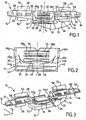
figure 1 est une vue schématique de face d'un dispositif de structure modulaire selon une première forme de réalisation de l'invention ; - la
figure 2 montre le module thermique du dispositif de lafigure 1 ; - la
figure 3 est une vue en perspective avec arrachement du dispositif de lafigure 1 ; - la
figure 4 est une vue en coupe verticale du module thermique du dispositif desfigures 1 et 3 ; - la
figure 5 est une vue en coupe selon la ligne V-V de lafigure 4 ; - la
figure 6 montre schématiquement la circulation de l'air dans la partie supérieure du module thermique de lafigure 4 ; - la
figure 7 est une vue en perspective montrant deux satellites de distribution faisant partie des modules de distribution ; - la
figure 8 est une vue en perspective d'un dispositif selon une autre forme de réalisation de l'invention ; - la
figure 9 est une vue en pérspective d'un module de distribution ; - la
figure 10 est une vue en perspective montrant des buses de distribution propres à s'adapter sur le module de distribution de lafigure 9 ; - la
figure 11 est une vue schématique en coupe horizontale d'un autre dispositif selon l'invention, dans lequel le flux d'air à température ajustée est obtenu par régulation de la température du fluide caloporteur qui traverse le radiateur de chauffage ; - la
figure 12 , est une vue en coupe selon la ligne XII-XII de lafigure 11 ; - la
figure 13 est une vue analogue à lafigure 11 dans une variante de réalisation ; - la
figure 14 est une vue en coupe verticale d'un module thermique selon une autre forme de réalisation ; - la
figure 15 est une vue en coupe selon la ligne XV-XV de lafigure 14 ; - la
figure 16 est une vue en coupe analogue à lafigure 4 dans une variante de réalisation ; - la
figure 17 est une vue en coupe selon la ligne XVII-XVII de lafigure 16 ; - la
figure 18 est une vue en perspective d'une poutre transversale intégrant un dispositif selon l'invention, des parties formant couvercle des modules de distribution étant enlevées ; et - la
figure 19 est une vue analogue à lafigure 18 , les parties formant couvercle étant mises en place.
- the
figure 1 is a schematic front view of a modular structure device according to a first embodiment of the invention; - the
figure 2 shows the thermal module of the device of thefigure 1 ; - the
figure 3 is a broken perspective view of the device of thefigure 1 ; - the
figure 4 is a vertical sectional view of the thermal module of the device of theFigures 1 and 3 ; - the
figure 5 is a sectional view along line VV of thefigure 4 ; - the
figure 6 schematically shows the flow of air in the upper part of the thermal module of thefigure 4 ; - the
figure 7 is a perspective view showing two distribution satellites forming part of the distribution modules; - the
figure 8 is a perspective view of a device according to another embodiment of the invention; - the
figure 9 is a perspective view of a distribution module; - the
figure 10 is a perspective view showing distribution nozzles adapted to fit on the distribution module of thefigure 9 ; - the
figure 11 is a schematic view in horizontal section of another device according to the invention, wherein the temperature-adjusted air flow is obtained by regulating the temperature of the heat transfer fluid which passes through the heating radiator; - the
figure 12 , is a sectional view along the line XII-XII of thefigure 11 ; - the
figure 13 is a view similar to thefigure 11 in an alternative embodiment; - the
figure 14 is a vertical sectional view of a thermal module according to another embodiment; - the
figure 15 is a sectional view along line XV-XV of thefigure 14 ; - the
figure 16 is a sectional view similar to thefigure 4 in an alternative embodiment; - the
figure 17 is a sectional view along the line XVII-XVII of thefigure 16 ; - the
figure 18 is a perspective view of a transverse beam incorporating a device according to the invention, the lid portions of the dispensing modules being removed; and - the
figure 19 is a view similar to thefigure 18 , the lid parts being put in place.
On se réfère d'abord conjointement aux
Le module de ventilation 14 est disposé à côté du module thermique 12, dans la direction transversale (axe Y) du véhicule. Il comprend un bloc d'entrée d'air (non représenté sur la
Le module thermique 12 (
Dans l'exemple, l'évaporateur 32 et les deux radiateurs 34 et 36 s'étendent dans des plans sensiblement horizontaux. Toutefois, une telle implantation n'a pas un caractère limitatif. L'évaporateur peut être placé dans toute position choisie depuis une position horizontale vers une position verticale. Le radiateur de chauffage 34, qui est placé en aval de l'évaporateur, peut être placé dans toute position choisie depuis une position parallèle à une position perpendiculaire à l'évaporateur. Le radiateur de chauffage électrique 36, qui est facultatif, est placé en aval du radiateur de chauffage 34 de préférence parallèlement ou légèrement incliné par rapport à celui-ci. Le radiateur 36 comprend de préférence des résistances à coefficient de température positif (encore appelées résistances CTP).In the example, the
Le module thermique 12 comprend en outre des moyens de réglage pour produire un flux d'air à température ajustée par mélange (mixage) en proportion variable d'un flux d'air chaud ayant traversé le ou les radiateurs de chauffage 34 et 36 et d'un flux d'air froid ayant contourné le radiateur de chauffage. Ces moyens de réglage comprennent, du côté droit et du côté gauche du module thermique 12, un canal latéral d'air chaud 38d, respectivement 38g, traversant chacun une moitié des radiateurs de chauffage 34 et 36 et un canal latéral d'air froid 40d, respectivement 40g, en dérivation du canal latéral d'air chaud. Comme on peut le voir plus particulièrement sur la
Un volet latéral de mixage 44d, respectivement 44g, est prévu dans le boîtier pour répartir en proportion variable le flux d'air chaud dans le canal latéral d'air chaud et le flux d'air froid dans le canal d'air froid. De chaque côté du module thermique 12, le canal latéral d'air chaud 38d (ou 38g) et le canal latéral d'air froid 40d (ou 40g) forment conjointement une sortie latéral 46d, respectivement 46g du module thermique. Dans l'exemple, chacun des volets latéraux de mixage 44d et 44g est implanté dans le module thermique, celui-ci incorporant ainsi la fonction de mixage. On comprendra que l'airtraverse d'abord l'évaporateur puis se partage en deux flux affectés respectivement à la partie droite et à la partie gauche. Dans chacune des parties ou moitiés, la température du flux d'air est réglée par mélange, en proportion variable, d'un flux d'air froid et d'un flux d'air chaud. On peut ainsi régler, de manière indépendante, la température du flux d'air envoyé dans les deux modules de distribution 16.A
Dans l'exemple, les volets de mixage sont illustrés schématiquement. Ils comprennent principalement deux volets de type papillon entre lesquels s'étend un volet à registre 48 qui est disposé entre l'évaporateur 32 et le radiateur de chauffage 34.In the example, the mixing flaps are schematically illustrated. They mainly comprise two butterfly flaps between which there extends a
Les deux modules de distribution 16 sont implantés respectivement du côté droit et du côté gauche du module thermique. Chacun possède une entrée 50 reliée à une sortie d'air latérale 46d ou 46g du module thermique. Chaque module de distribution 16 est réalisé sous la forme d'un boîtier allongé 52 qui occupe à chaque fois une partie de la planche de bord du véhicule. Ce boîtier allongé 52 délimite une chambre intérieure qui alimente plusieurs sorties d'air : une sortie 54 dirigée vers le haut, une sortie 56 dirigée vers le bas et trois sorties intermédiaires ou sorties frontales 58. La sortie haute 54 est propre à alimenter au moins une buse de dégivrage/désembuage du pare-brise, tandis que la sortie basse 56 est propre à alimenter au moins une buse de chauffage-pieds vers la partie inférieure de l'habitacle. Enfin, les sorties 58 alimentent des aérateurs aménagés essentiellement dans la planche de bord du véhicule. Chacun des modules 16 incorpore des moyens de répartition, qui seront décrits plus loin, pour répartir le flux d'air entre les sorties précitées en fonction des souhaits du ou des occupants du véhicule.The two
La
Comme on peut le voir sur la
Sur la coupe transversale de la
Un volet central de mixage 72 est placé dans le boîtier pour permettre de faire varier, en proportion réglable, le flux d'air froid et le flux d'air chaud et procurer un flux d'air à température ajustée qui est envoyé dans un canal comme montré par la flèche F4. Ceci permet d'alimenter une sortie 74 du module thermique. Celle-ci alimente à son tour au moins un autre module de distribution 76 (représenté schématiquement) pour distribuer un flux d'air à température ajustée vers l'arrière de l'habitacle. Là aussi, la fonction de mixage, pour cet autre module de distribution, pourrait être déportée dans celui-ci.A
Le dispositif de la
Le (s) module(s) de distribution arrière distribue (nt) de l'air vers des bouches de distribution placées à l'arrière du véhicule pour envoyer de l'air au travers d'aérateurs, de bouches de distribution inférieures et vers les vitres latérales du véhicule.The rear distribution module (s) distributes air to distribution outlets located at the rear of the vehicle to send air through aerators, lower distribution outlets and the side windows of the vehicle.
On se réfère maintenant à la
Cependant, ils trouvent avantageusement une intégration dans un dispositif 90, selon une autre forme de réalisation de l'invention, comme montré à la
On aperçoit également sur la
Le module de distribution 16 de la
On se réfère maintenant aux
Dans la variante de réalisation de la
Dans cet exemple de réalisation, les dimensions des deux canalisations latérales d'air froid 112d et 112g ont été réduites par rapport à la forme de réalisation des
Ceci permet de dégager de la place pour deux autres canalisations d'air froid 116 et 118 qui peuvent être dédiées à d'autres fonctions, par exemple au refroidissement de composants électriques ou encore à la réfrigération d'un compartiment à bouteille ou de la boîte à gants du véhicule.This allows to clear space for two other
Dans la forme de réalisation des
Dans la forme de réalisation des
On se réfère maintenant aux
Dans la plupart des formes de réalisation précitées, chacun des modules de distribution est alimenté par un conduit d'air unique, ce qui a pour résultat que les sorties d'air sont à la même température. Pour éviter cet inconvénient, il est possible, comme montré précédemment, d'ajouter des canalisations d'air froid pour créer une stratification de température à deux ou à trois niveaux. Il est possible aussi de créer une stratification fixe en divisant chaque conduit d'air en un conduit d'air chaud et un conduit d'air froid.In most of the above embodiments, each of the distribution modules is powered by a single air duct, resulting in the air outlets being at the same temperature. To avoid this, it is possible, as shown above, to add cold air pipes to create a temperature stratification at two or three levels. It is also possible to create a fixed lamination by dividing each air duct into a hot air duct and a cold duct.
Une autre solution consiste à transférer des sources thermiques à l'intérieur de chacun des modules de distribution 16, ou directement dans les conduits alimentant les sorties basses (sorties pieds) ou les sorties hautes (sorties dégivrage/désembuage) pour réchauffer ces sorties à une température supérieure à celle des sorties d'aération.Another solution consists in transferring thermal sources inside each of the
On se réfère maintenant à la
La conception modulaire du dispositif de l'invention, avec des modules situés sensiblement sur un même niveau horizontal, facilite son intégration dans un véhicule automobile dépourvu de console.The modular design of the device of the invention, with modules located substantially on the same horizontal level, facilitates its integration in a motor vehicle without a console.
Claims (28)
- Heating-ventilation and/or air-conditioning device for the passenger compartment of a motor vehicle, which comprises means for producing a flow of blown air at an adjusted temperature, and also de-icing, ventilation and foot heater outlets that are supplied with this stream of temperature-adjusted air, is suitable for being connected to vents opening into the passenger compartment and is composed of modules grouped together substantially at the same horizontal level and comprising:- at least one ventilation module (14) designed to produce a stream of blown air;- at least one thermal module (12) designed to be fitted into a central region of the passenger compartment and comprising an air inlet (28) for the blown air, heat exchangers (32, 34, 36) suitable for the flow of air to pass through them, and at least one lateral air outlet (46d, 46g); and- at least one distribution module (16) having an inlet (50) connected to a lateral air outlet (46d, 46g) of the thermal module and including distribution means for distributing the flow of air between air outlets (54, 56, 58) opening into chosen regions of the passenger compartment,characterized in that the thermal module (12) includes two lateral air outlets (46d, 46g) opening on the right-hand side and on the left-hand side respectively, and in that the device comprises two distribution modules (16) designed to be fitted on the right-hand side and on the left-hand side of the thermal module respectively, each having an inlet (50) connected to a lateral air outlet (46d, 46g) of the thermal module.
- Device according to Claim 1, characterized in that the ventilation module (14) is placed alongside the thermal module (12) in the transverse direction (Y axis) of the vehicle.
- Device according to Claim 1, characterized in that the ventilation module (14) is placed alongside the thermal module (12) in the longitudinal direction (X axis) of the vehicle.
- Device according to one of Claims 1 to 3, characterized in that the ventilation module (14) comprises an air intake block (18) for external air and/or recirculated air, a turbine (22) for producing a flow of blown air, and an outlet duct (26) for bringing the flow of blown air to the inlet (28) of the thermal module.
- Device according to one of Claims 1 to 4, characterized in that the inlet (28) of the thermal module (12) is located in the lower part of the latter and in that the thermal module (12) houses, in succession from the bottom up, an air-conditioning evaporator (32) and at least one heating radiator (34, 36).
- Device according to Claim 5, characterized in that the thermal module (12) houses a first heating radiator (34), which is placed above the evaporator (32) and through which a hot heat-transfer fluid flows, and a second heating radiator (36) of the electrical type, which is placed above the first heating radiator (34).
- Device according to either of Claims 5 and 6, characterized in that the evaporator (32) and the heating radiator (34) each lie in a plane inclined at between 0° and 90° to the horizontal.
- Device according to Claim 7, characterized in that the evaporator (32) lies in a plane inclined at between 20° and 40° to the horizontal.
- Device according to one of Claims 1 to 8, characterized in that it comprises adjustment means (44d, 44g, 48) for producing a flow of temperature-adjusted air resulting from mixing, in a variable proportion, a flow of hot air that has passed through the heating radiator (34, 36) and a flow of cold air that has by-passed the heating radiator (34, 36).
- Device according to Claim 9, characterized in that the adjustment means, comprise, each time, on the right-hand side and left-hand side, a lateral hot-air channel (38d, 38g) passing through part of the heating radiator (34, 36) and a lateral cold-air channel (40d, 40g) branched off the lateral hot-air channel, and also a lateral mixing flap (44d, 44g) for distributing in a variable proportion the flow of hot air in the lateral hot-air channel and the flow of cold air in the lateral cold-air channel, the lateral hot-air channel (38d, 38g) and the lateral cold-air channel (40d, 40g) together forming a lateral outlet (46d, 46g) of the thermal module.
- Device according to Claim 10, characterized in that each lateral mixing flap (44d, 44g) is fitted into the thermal module (12).
- Device according to Claim 10, characterized in that each lateral mixing flap is fitted into a distribution module (16) located on the right-hand side or the left-hand side with respect to the thermal module (12).
- Device according to Claim 8, characterized in that the adjustment means furthermore include a central air channel (66) for hot air that has passed through part of the heating radiator (34, 36) and a central air channel (70) for cold air branched off the central air channel (66), and also a central mixing flap (72) for distributing in a variable proportion the flow of air going towards the central hot-air channel (66) and the flow of air in the central cold-air channel (70), the two central channels (66, 70) together forming a central outlet (74) of the thermal module (12), said central outlet (74) being designed to supply at least one other distribution module (76) so as to distribute a flow of temperature-adjusted air towards the rear of the passenger compartment.
- Device according to Claim 13, characterized in that the central mixing flap (72) is fitted into the thermal module (12).
- Device according to Claim 13, characterized in that the central mixing flap (72) is fitted in the other distribution module (76).
- Device according to one of Claims 13 to 15, characterized in that the adjustment means furthermore include a distribution flap (73) that can be moved between a first position (73a), for sending the flow of temperature-adjusted air into the lateral outlet(s) (46d, 46g) of the thermal module (12) supplying the front of the passenger compartment, and a second position (73b), for sending the flow of temperature-adjusted air into the central outlet (74) of the thermal module (12) supplying the rear of the passenger compartment.
- Device according to one of Claims 1 to 16, characterized in that it includes two lateral outlet chambers (108d, 108g) located downstream of the heating radiator (34, 36) and terminating in the respective lateral outlets (46d, 46g) of the thermal module.
- Device according to Claim 17, characterized in that it further includes at least one lateral cold-air duct (112d, 112g) for bringing a flow of cold air taken from the thermal module (12), upstream of the heating radiator (34), directly into a distribution module (16) fitted on the right-hand side or the left-hand side.
- Device according to Claim 17, characterized in that it further includes a central outlet chamber located downstream of the heating radiator (34, 36) and terminating in a central outlet of the thermal unit (12), said central outlet chamber being designed to supply at least one other distribution module (76) for distributing a flow of temperature-adjusted air into the rear of the passenger compartment.
- Device according to Claim 17, characterized in that it further includes at least one central cold-air duct for bringing a stream of cold air taken from the thermal module (12), upstream of the heating radiator (34), into the other distribution module (76) or into a compartment to be cooled.
- Device according to one of Claims 1 to 17, characterized in that the distribution module(s) (16) each has (have) a bottom outlet (56) opening towards the feet, a top outlet (54) opening towards the windscreen, and at least one intermediate outlet (58) opening frontally.
- Device according to one of Claims 1 to 8, characterized in that it includes adjustment means (104) acting on the flow rate, and therefore the temperature, of a heat-transfer fluid passing through the heating radiator (34) in order to produce a flow of temperature-adjusted air.
- Device according to Claim 22, characterized in that it includes two lateral outlet chambers (108d, 108g) located downstream of the heating radiator (34, 36) and terminating in the respective lateral outlets (46d, 46g) of the thermal module.
- Device according to Claim 23, characterized in that it further includes at least one lateral cold-air duct (112d, 112g) for bringing a flow of cold air taken from the thermal module (12), upstream of the heating radiator (34), into a distribution module (16) fitted on the right-hand side or the left-hand side.
- Device according to Claim 23, characterized in that it further includes a central outlet chamber located downstream of the heating radiator (34, 36) and terminating in a central outlet of the thermal unit (12), said central outlet chamber being designed to supply at least one other distribution module (76) for distributing a flow of temperature-adjusted air into the rear of the passenger compartment.
- Device according to Claim 23, characterized in that it further includes at least one central cold-air duct for bringing a flow of cold air taken from the thermal module (12), upstream of the heating radiator (34), into the other distribution module (76) or into a compartment to be cooled.
- Device according to one of Claims 1 to 23, characterized in that the distribution module(s) (16) each has(have) a bottom outlet (56) opening towards the feet, a top outlet (54) opening towards the windscreen, and at least one intermediate outlet (58) opening frontally.
- Device according to one of Claims 1 to 27, characterized in that the modules (12, 14, 16) making up the device are incorporated into a transverse member (128) of the vehicle.
Applications Claiming Priority (3)
| Application Number | Priority Date | Filing Date | Title |
|---|---|---|---|
| FR0303116A FR2852271B1 (en) | 2003-03-13 | 2003-03-13 | DEVICE FOR HEATING-VENTILATION AND / OR AIR CONDITIONING OF COMPACT STRUCTURE FOR THE HABITACLE OF A MOTOR VEHICLE |
| FR0303116 | 2003-03-13 | ||
| PCT/IB2004/000790 WO2004080737A1 (en) | 2003-03-13 | 2004-03-09 | Heating and ventilation and/or air conditioning device with a compact construction for a motor vehicle passenger compartment |
Publications (3)
| Publication Number | Publication Date |
|---|---|
| EP1601543A1 EP1601543A1 (en) | 2005-12-07 |
| EP1601543B1 EP1601543B1 (en) | 2007-05-16 |
| EP1601543B2 true EP1601543B2 (en) | 2016-07-20 |
Family
ID=32893275
Family Applications (1)
| Application Number | Title | Priority Date | Filing Date |
|---|---|---|---|
| EP04718702.6A Expired - Lifetime EP1601543B2 (en) | 2003-03-13 | 2004-03-09 | Heating and ventilation and/or air conditioning device with a compact construction for a motor vehicle passenger compartment |
Country Status (8)
| Country | Link |
|---|---|
| US (1) | US8944144B2 (en) |
| EP (1) | EP1601543B2 (en) |
| JP (1) | JP4688790B2 (en) |
| AT (1) | ATE362433T1 (en) |
| DE (1) | DE602004006496T2 (en) |
| ES (1) | ES2287709T5 (en) |
| FR (1) | FR2852271B1 (en) |
| WO (1) | WO2004080737A1 (en) |
Families Citing this family (14)
| Publication number | Priority date | Publication date | Assignee | Title |
|---|---|---|---|---|
| ATE423028T1 (en) * | 2004-06-24 | 2009-03-15 | Behr Gmbh & Co Kg | AIR CONDITIONING, PARTICULARLY MOTOR VEHICLE AIR CONDITIONING |
| DE102005031912A1 (en) * | 2005-07-07 | 2007-01-11 | Siemens Ag | Air duct system for vehicles, in particular for passenger rail vehicles |
| DE102007035240A1 (en) * | 2007-07-25 | 2009-01-29 | Behr Gmbh & Co. Kg | Heating and/or air-conditioning system for motor vehicle, has air outlet arranged at region of through openings for cool air and communicated with middle nozzle and/or side nozzle |
| US9453654B2 (en) * | 2007-09-21 | 2016-09-27 | Airgreen Ltd. | Method of dispersing air, jets from air conditioning systems and mixing them with the ambient air of an enclosure for better comfort and apparatus to create the jets |
| US8408281B2 (en) * | 2007-10-15 | 2013-04-02 | Lockheed Martin Corporation | System, method, and apparatus for pulsed-jet-enhanced heat exchanger |
| US20110266075A1 (en) * | 2010-04-28 | 2011-11-03 | Guzelimian Harry L | Energy Generation System for Electric, Hybrid and Conventional Vehicles |
| DE102011050457A1 (en) * | 2011-05-18 | 2012-11-22 | Visteon Global Technologies, Inc. | Air conditioner with foot outlet |
| US20140060795A1 (en) * | 2012-09-06 | 2014-03-06 | Jeffrey N. Yu | Concealed dynamic ventilation system |
| US9168810B2 (en) * | 2012-10-09 | 2015-10-27 | Delphi Technologies, Inc. | Heating and cooling system for occupants of the rear portion of a vehicle |
| US10377347B2 (en) * | 2015-03-09 | 2019-08-13 | Ford Global Technologies, Llc | Low-profile ventilation system for a motor vehicle and related method of providing a low-profile ventilation system |
| JP2017013704A (en) * | 2015-07-03 | 2017-01-19 | 株式会社ヴァレオジャパン | Air conditioner for vehicle and vehicle mounted with air conditioner for vehicle |
| JP6078606B1 (en) * | 2015-09-30 | 2017-02-08 | 富士重工業株式会社 | Automotive air conditioner |
| KR102580906B1 (en) * | 2016-12-27 | 2023-09-21 | 한온시스템 주식회사 | Independent type air conditioning system |
| CN110450636A (en) * | 2019-08-09 | 2019-11-15 | 北京长城华冠汽车科技股份有限公司 | Instrument panel assembly and vehicle with it |
Family Cites Families (33)
| Publication number | Priority date | Publication date | Assignee | Title |
|---|---|---|---|---|
| GB2049159B (en) * | 1978-12-28 | 1983-06-15 | Diesel Kiki Co | Air conditioner for motor vehicles |
| JPH051451Y2 (en) | 1986-07-18 | 1993-01-14 | ||
| WO1989008032A1 (en) | 1988-03-04 | 1989-09-08 | Zaporozhsky Avtomobilny Zavod "Kommunar" (Proizvod | Air conditioner for transport means |
| FR2637548B1 (en) | 1988-10-12 | 1994-02-18 | Valeo | AIR AND HEATING AND / OR AIR CONDITIONING SYSTEM FOR A MOTOR VEHICLE |
| JP2566044B2 (en) * | 1990-05-25 | 1996-12-25 | 日産自動車株式会社 | Heater unit structure of vehicle air conditioner |
| JPH051451U (en) | 1991-06-25 | 1993-01-14 | 株式会社日立ホームテツク | Tableware dryer |
| JPH0576812U (en) | 1992-03-26 | 1993-10-19 | 日野自動車工業株式会社 | Vehicle air conditioner |
| JPH05294129A (en) * | 1992-04-22 | 1993-11-09 | Hitachi Ltd | Air conditioner for special vehicle with cabin |
| FR2697211B1 (en) * | 1992-10-26 | 1994-12-09 | Valeo Thermique Habitacle | Cooling and air conditioning device for electric vehicle. |
| JP3239495B2 (en) * | 1992-12-22 | 2001-12-17 | 株式会社デンソー | Air conditioner |
| IT1257964B (en) * | 1992-12-30 | 1996-02-19 | Borletti Climatizzazione | DASHBOARD FOR VEHICLES, WITH BUILT-IN HEAT EXCHANGER. |
| JPH06286456A (en) * | 1993-04-01 | 1994-10-11 | Nippondenso Co Ltd | Air conditioner for vehicle |
| JP3187666B2 (en) * | 1994-10-25 | 2001-07-11 | ダイハツ工業株式会社 | Air conditioning air duct structure |
| EP0713798B1 (en) * | 1994-11-25 | 1998-04-29 | Delphi Automotive Systems Deutschland GmbH | Dashboard assembly |
| FR2735426B1 (en) | 1995-06-14 | 1997-07-18 | Valeo Climatisation | DEVICE FOR HEATING-VENTILATION AND / OR AIR CONDITIONING OF THE INTERIOR OF A MOTOR VEHICLE |
| JPH09216511A (en) * | 1996-02-13 | 1997-08-19 | Denso Corp | Air conditioner for automobile |
| DE19626441B4 (en) | 1996-06-20 | 2004-03-25 | Sommer-Allibert-Lignotock Gmbh | Cockpit for motor vehicles |
| DE19739578C2 (en) | 1997-09-10 | 2000-03-02 | Behr Gmbh & Co | Heating or air conditioning for a motor vehicle |
| GB2332887B (en) * | 1997-11-19 | 2002-02-13 | Textron Automotive U K | Fluid reservoir-air duct arrangement |
| JPH11208241A (en) * | 1998-01-22 | 1999-08-03 | Calsonic Corp | Vehicle air conditioner |
| FR2775221B1 (en) * | 1998-02-20 | 2000-05-26 | Renault | VENTILATION, HEATING AND AIR CONDITIONING DEVICE FOR A PASSENGER COMPARTMENT OF A MOTOR VEHICLE |
| JPH11301251A (en) * | 1998-04-15 | 1999-11-02 | Zexel:Kk | Air conditioner for automobile |
| JP2000062438A (en) * | 1998-08-25 | 2000-02-29 | Zexel Corp | Vent distributor for automotive air conditioner |
| JP3470047B2 (en) * | 1998-09-08 | 2003-11-25 | 西川化成株式会社 | Automotive air conditioners |
| FR2783465B1 (en) * | 1999-10-11 | 2001-11-16 | Valeo Climatisation | INTEGRATED HEATING AND AIR CONDITIONING DEVICE IN A MOTOR VEHICLE DASHBOARD |
| JP2001171332A (en) | 1999-12-17 | 2001-06-26 | Denso Corp | Vehicle air conditioner |
| ATE290964T1 (en) * | 1999-12-21 | 2005-04-15 | Behr Gmbh & Co Kg | HEATING OR AIR CONDITIONING SYSTEM FOR A MOTOR VEHICLE |
| JP4192376B2 (en) * | 1999-12-24 | 2008-12-10 | 株式会社デンソー | Cockpit module assembly for vehicle |
| JP2002019448A (en) * | 2000-07-03 | 2002-01-23 | Denso Corp | Air conditioner for vehicle |
| DE10042683A1 (en) | 2000-08-31 | 2002-03-14 | Behr Gmbh & Co | Air conditioning unit for motor vehicles has two housing sections ate 90o to each other, and connected via flow channel connector |
| DE10045438A1 (en) | 2000-09-14 | 2002-03-28 | Behr Gmbh & Co | Air conditioning for a motor vehicle |
| JP2004224081A (en) * | 2003-01-20 | 2004-08-12 | Denso Corp | Air conditioner |
| FR2859134B1 (en) | 2003-08-29 | 2007-09-28 | Valeo Climatisation | AIR DISTRIBUTION MODULE FOR A VENTILATION, HEATING AND / OR AIR CONDITIONING FACILITY |
-
2003
- 2003-03-13 FR FR0303116A patent/FR2852271B1/en not_active Expired - Lifetime
-
2004
- 2004-03-09 AT AT04718702T patent/ATE362433T1/en not_active IP Right Cessation
- 2004-03-09 WO PCT/IB2004/000790 patent/WO2004080737A1/en active IP Right Grant
- 2004-03-09 ES ES04718702.6T patent/ES2287709T5/en not_active Expired - Lifetime
- 2004-03-09 EP EP04718702.6A patent/EP1601543B2/en not_active Expired - Lifetime
- 2004-03-09 JP JP2006506355A patent/JP4688790B2/en not_active Expired - Fee Related
- 2004-03-09 US US10/549,257 patent/US8944144B2/en active Active
- 2004-03-09 DE DE602004006496T patent/DE602004006496T2/en not_active Expired - Lifetime
Also Published As
| Publication number | Publication date |
|---|---|
| FR2852271B1 (en) | 2006-07-28 |
| EP1601543B1 (en) | 2007-05-16 |
| JP2006520298A (en) | 2006-09-07 |
| FR2852271A1 (en) | 2004-09-17 |
| WO2004080737A1 (en) | 2004-09-23 |
| ES2287709T5 (en) | 2017-01-31 |
| US8944144B2 (en) | 2015-02-03 |
| EP1601543A1 (en) | 2005-12-07 |
| DE602004006496D1 (en) | 2007-06-28 |
| ATE362433T1 (en) | 2007-06-15 |
| DE602004006496T2 (en) | 2008-02-07 |
| ES2287709T3 (en) | 2007-12-16 |
| US20060207758A1 (en) | 2006-09-21 |
| JP4688790B2 (en) | 2011-05-25 |
Similar Documents
| Publication | Publication Date | Title |
|---|---|---|
| EP1601543B2 (en) | Heating and ventilation and/or air conditioning device with a compact construction for a motor vehicle passenger compartment | |
| EP1062109B1 (en) | Ventilating, heating and air conditioning device for motor vehicle passenger compartment | |
| EP1185429B1 (en) | Air conditioning device for motor vehicle | |
| EP3319824B1 (en) | Motor vehicle heating, ventilation and/or air conditioning device and corresponding additional module and method of assembly | |
| EP2228242B1 (en) | Heating, ventilating and/or air conditioning device with modified air duct depending on the version. | |
| FR2706816A1 (en) | Apparatus for heating-ventilating and/or air-conditioning the passenger compartment of a motor vehicle, especially an electric vehicle | |
| WO2021111047A1 (en) | Heating, ventilation and/or air-conditioning device for a motor vehicle | |
| FR2735425A1 (en) | DEVICE FOR HEATING AND / OR AIR CONDITIONING THE CABIN IN A MOTOR VEHICLE | |
| FR2742383A1 (en) | Heater or air-conditioner for passenger space of motor vehicle | |
| FR2717747A1 (en) | Heating and air-conditioning of automobile passenger compartment | |
| EP2858842B1 (en) | Equipment for controlling the temperature of a passenger compartment of a vehicle, in particular an electric vehicle | |
| EP0289405A1 (en) | Heating and ventilation apparatus, especially for the passenger compartment of a motor vehicle | |
| FR2787392A1 (en) | REDUCED SIZE HEATING AND AIR CONDITIONING DEVICE FOR A MOTOR VEHICLE | |
| EP0961698B2 (en) | Heating/air-conditioning device integrated in a motor vehicle instrument panel | |
| EP2895343B1 (en) | Compact heating/air-conditioning unit for motor vehicles | |
| FR2889486A1 (en) | Air flow distributing device for motor vehicle heating, ventilation and/or air-conditioning installation, has distribution unit with separation wall defining front and rear zones to divide air flow into two flows that enter directly zones | |
| EP1484206B1 (en) | A heating/air-conditioning device suitable for housing in a vehicle flat instrument panel | |
| FR2754491A1 (en) | HEATING-AIR CONDITIONING VEHICLE DEVICE WITH SEPARATE ADJUSTMENT OF THE RIGHT AND LEFT SIDE OF THE CABINET | |
| EP1405743B1 (en) | Heating and/or air conditioning device for a motor vehicle passenger compartment, with reduced pressure loss | |
| FR2740398A1 (en) | Heater air conditioner for motor vehicle compartment | |
| FR2473430A1 (en) | Car heating and ventilating air conditioner - has heat exchanger powered fan with multiple outlets and regulating valves | |
| EP2886378A1 (en) | Heating, ventilation and/or air conditioning installation for motor vehicle passenger compartment | |
| FR2769692A1 (en) | AIR TREATMENT UNIT WITH IMPROVED TEMPERATURE MANAGEMENT, FOR A HEATING AND / OR AIR CONDITIONING SYSTEM, ESPECIALLY A MOTOR VEHICLE | |
| FR3058362A1 (en) | DEVICE FOR HEATING, VENTILATION AND / OR AIR CONDITIONING FOR A HABITACLE OF A MOTOR VEHICLE | |
| FR2854104A1 (en) | Heat ventilation and air-conditioning device for vehicle passenger compartment, has exterior duct including inlet that opens in outlet chamber and outlet that feeds lower nozzle at interior of passenger compartment |
Legal Events
| Date | Code | Title | Description |
|---|---|---|---|
| PUAI | Public reference made under article 153(3) epc to a published international application that has entered the european phase |
Free format text: ORIGINAL CODE: 0009012 |
|
| 17P | Request for examination filed |
Effective date: 20050829 |
|
| AK | Designated contracting states |
Kind code of ref document: A1 Designated state(s): AT BE BG CH CY CZ DE DK EE ES FI FR GB GR HU IE IT LI LU MC NL PL PT RO SE SI SK TR |
|
| AX | Request for extension of the european patent |
Extension state: AL LT LV MK |
|
| DAX | Request for extension of the european patent (deleted) | ||
| GRAP | Despatch of communication of intention to grant a patent |
Free format text: ORIGINAL CODE: EPIDOSNIGR1 |
|
| GRAS | Grant fee paid |
Free format text: ORIGINAL CODE: EPIDOSNIGR3 |
|
| GRAA | (expected) grant |
Free format text: ORIGINAL CODE: 0009210 |
|
| AK | Designated contracting states |
Kind code of ref document: B1 Designated state(s): AT BE BG CH CY CZ DE DK EE ES FI FR GB GR HU IE IT LI LU MC NL PL PT RO SE SI SK TR |
|
| PG25 | Lapsed in a contracting state [announced via postgrant information from national office to epo] |
Ref country code: FI Free format text: LAPSE BECAUSE OF FAILURE TO SUBMIT A TRANSLATION OF THE DESCRIPTION OR TO PAY THE FEE WITHIN THE PRESCRIBED TIME-LIMIT Effective date: 20070516 |
|
| REG | Reference to a national code |
Ref country code: GB Ref legal event code: FG4D Free format text: NOT ENGLISH |
|
| REG | Reference to a national code |
Ref country code: CH Ref legal event code: EP |
|
| REG | Reference to a national code |
Ref country code: IE Ref legal event code: FG4D Free format text: LANGUAGE OF EP DOCUMENT: FRENCH |
|
| REF | Corresponds to: |
Ref document number: 602004006496 Country of ref document: DE Date of ref document: 20070628 Kind code of ref document: P |
|
| PG25 | Lapsed in a contracting state [announced via postgrant information from national office to epo] |
Ref country code: SE Free format text: LAPSE BECAUSE OF FAILURE TO SUBMIT A TRANSLATION OF THE DESCRIPTION OR TO PAY THE FEE WITHIN THE PRESCRIBED TIME-LIMIT Effective date: 20070816 |
|
| NLV1 | Nl: lapsed or annulled due to failure to fulfill the requirements of art. 29p and 29m of the patents act | ||
| PG25 | Lapsed in a contracting state [announced via postgrant information from national office to epo] |
Ref country code: AT Free format text: LAPSE BECAUSE OF FAILURE TO SUBMIT A TRANSLATION OF THE DESCRIPTION OR TO PAY THE FEE WITHIN THE PRESCRIBED TIME-LIMIT Effective date: 20070516 Ref country code: PL Free format text: LAPSE BECAUSE OF FAILURE TO SUBMIT A TRANSLATION OF THE DESCRIPTION OR TO PAY THE FEE WITHIN THE PRESCRIBED TIME-LIMIT Effective date: 20070516 |
|
| GBV | Gb: ep patent (uk) treated as always having been void in accordance with gb section 77(7)/1977 [no translation filed] |
Effective date: 20070516 |
|
| REG | Reference to a national code |
Ref country code: ES Ref legal event code: FG2A Ref document number: 2287709 Country of ref document: ES Kind code of ref document: T3 |
|
| REG | Reference to a national code |
Ref country code: IE Ref legal event code: FD4D |
|
| PG25 | Lapsed in a contracting state [announced via postgrant information from national office to epo] |
Ref country code: PT Free format text: LAPSE BECAUSE OF FAILURE TO SUBMIT A TRANSLATION OF THE DESCRIPTION OR TO PAY THE FEE WITHIN THE PRESCRIBED TIME-LIMIT Effective date: 20071016 Ref country code: NL Free format text: LAPSE BECAUSE OF FAILURE TO SUBMIT A TRANSLATION OF THE DESCRIPTION OR TO PAY THE FEE WITHIN THE PRESCRIBED TIME-LIMIT Effective date: 20070516 Ref country code: DK Free format text: LAPSE BECAUSE OF FAILURE TO SUBMIT A TRANSLATION OF THE DESCRIPTION OR TO PAY THE FEE WITHIN THE PRESCRIBED TIME-LIMIT Effective date: 20070516 Ref country code: IE Free format text: LAPSE BECAUSE OF FAILURE TO SUBMIT A TRANSLATION OF THE DESCRIPTION OR TO PAY THE FEE WITHIN THE PRESCRIBED TIME-LIMIT Effective date: 20070516 Ref country code: BG Free format text: LAPSE BECAUSE OF FAILURE TO SUBMIT A TRANSLATION OF THE DESCRIPTION OR TO PAY THE FEE WITHIN THE PRESCRIBED TIME-LIMIT Effective date: 20070816 Ref country code: SI Free format text: LAPSE BECAUSE OF FAILURE TO SUBMIT A TRANSLATION OF THE DESCRIPTION OR TO PAY THE FEE WITHIN THE PRESCRIBED TIME-LIMIT Effective date: 20070516 |
|
| PLBI | Opposition filed |
Free format text: ORIGINAL CODE: 0009260 |
|
| PG25 | Lapsed in a contracting state [announced via postgrant information from national office to epo] |
Ref country code: SK Free format text: LAPSE BECAUSE OF FAILURE TO SUBMIT A TRANSLATION OF THE DESCRIPTION OR TO PAY THE FEE WITHIN THE PRESCRIBED TIME-LIMIT Effective date: 20070516 |
|
| PLAX | Notice of opposition and request to file observation + time limit sent |
Free format text: ORIGINAL CODE: EPIDOSNOBS2 |
|
| 26 | Opposition filed |
Opponent name: BEHR GMBH & CO. KG Effective date: 20080218 |
|
| PG25 | Lapsed in a contracting state [announced via postgrant information from national office to epo] |
Ref country code: GB Free format text: LAPSE BECAUSE OF FAILURE TO SUBMIT A TRANSLATION OF THE DESCRIPTION OR TO PAY THE FEE WITHIN THE PRESCRIBED TIME-LIMIT Effective date: 20070516 Ref country code: GR Free format text: LAPSE BECAUSE OF FAILURE TO SUBMIT A TRANSLATION OF THE DESCRIPTION OR TO PAY THE FEE WITHIN THE PRESCRIBED TIME-LIMIT Effective date: 20070817 |
|
| PG25 | Lapsed in a contracting state [announced via postgrant information from national office to epo] |
Ref country code: RO Free format text: LAPSE BECAUSE OF FAILURE TO SUBMIT A TRANSLATION OF THE DESCRIPTION OR TO PAY THE FEE WITHIN THE PRESCRIBED TIME-LIMIT Effective date: 20070516 |
|
| PLAF | Information modified related to communication of a notice of opposition and request to file observations + time limit |
Free format text: ORIGINAL CODE: EPIDOSCOBS2 |
|
| PLBB | Reply of patent proprietor to notice(s) of opposition received |
Free format text: ORIGINAL CODE: EPIDOSNOBS3 |
|
| BERE | Be: lapsed |
Owner name: VALEO SYSTEMES THERMIQUES Effective date: 20080331 |
|
| PG25 | Lapsed in a contracting state [announced via postgrant information from national office to epo] |
Ref country code: MC Free format text: LAPSE BECAUSE OF NON-PAYMENT OF DUE FEES Effective date: 20080331 |
|
| REG | Reference to a national code |
Ref country code: CH Ref legal event code: PL |
|
| PG25 | Lapsed in a contracting state [announced via postgrant information from national office to epo] |
Ref country code: EE Free format text: LAPSE BECAUSE OF FAILURE TO SUBMIT A TRANSLATION OF THE DESCRIPTION OR TO PAY THE FEE WITHIN THE PRESCRIBED TIME-LIMIT Effective date: 20070516 Ref country code: CH Free format text: LAPSE BECAUSE OF NON-PAYMENT OF DUE FEES Effective date: 20080331 Ref country code: LI Free format text: LAPSE BECAUSE OF NON-PAYMENT OF DUE FEES Effective date: 20080331 |
|
| PG25 | Lapsed in a contracting state [announced via postgrant information from national office to epo] |
Ref country code: BE Free format text: LAPSE BECAUSE OF NON-PAYMENT OF DUE FEES Effective date: 20080331 |
|
| PG25 | Lapsed in a contracting state [announced via postgrant information from national office to epo] |
Ref country code: CY Free format text: LAPSE BECAUSE OF FAILURE TO SUBMIT A TRANSLATION OF THE DESCRIPTION OR TO PAY THE FEE WITHIN THE PRESCRIBED TIME-LIMIT Effective date: 20070516 |
|
| PG25 | Lapsed in a contracting state [announced via postgrant information from national office to epo] |
Ref country code: HU Free format text: LAPSE BECAUSE OF FAILURE TO SUBMIT A TRANSLATION OF THE DESCRIPTION OR TO PAY THE FEE WITHIN THE PRESCRIBED TIME-LIMIT Effective date: 20071117 Ref country code: LU Free format text: LAPSE BECAUSE OF NON-PAYMENT OF DUE FEES Effective date: 20080309 |
|
| PG25 | Lapsed in a contracting state [announced via postgrant information from national office to epo] |
Ref country code: TR Free format text: LAPSE BECAUSE OF FAILURE TO SUBMIT A TRANSLATION OF THE DESCRIPTION OR TO PAY THE FEE WITHIN THE PRESCRIBED TIME-LIMIT Effective date: 20070516 |
|
| PLAB | Opposition data, opponent's data or that of the opponent's representative modified |
Free format text: ORIGINAL CODE: 0009299OPPO |
|
| R26 | Opposition filed (corrected) |
Opponent name: BEHR GMBH & CO. KG Effective date: 20080218 |
|
| APBM | Appeal reference recorded |
Free format text: ORIGINAL CODE: EPIDOSNREFNO |
|
| APBP | Date of receipt of notice of appeal recorded |
Free format text: ORIGINAL CODE: EPIDOSNNOA2O |
|
| APAH | Appeal reference modified |
Free format text: ORIGINAL CODE: EPIDOSCREFNO |
|
| APBM | Appeal reference recorded |
Free format text: ORIGINAL CODE: EPIDOSNREFNO |
|
| APBP | Date of receipt of notice of appeal recorded |
Free format text: ORIGINAL CODE: EPIDOSNNOA2O |
|
| APBQ | Date of receipt of statement of grounds of appeal recorded |
Free format text: ORIGINAL CODE: EPIDOSNNOA3O |
|
| APBQ | Date of receipt of statement of grounds of appeal recorded |
Free format text: ORIGINAL CODE: EPIDOSNNOA3O |
|
| PLAB | Opposition data, opponent's data or that of the opponent's representative modified |
Free format text: ORIGINAL CODE: 0009299OPPO |
|
| R26 | Opposition filed (corrected) |
Opponent name: MAHLE BEHR GMBH & CO. KG Effective date: 20080218 |
|
| APBU | Appeal procedure closed |
Free format text: ORIGINAL CODE: EPIDOSNNOA9O |
|
| REG | Reference to a national code |
Ref country code: FR Ref legal event code: PLFP Year of fee payment: 13 |
|
| PGFP | Annual fee paid to national office [announced via postgrant information from national office to epo] |
Ref country code: DE Payment date: 20160316 Year of fee payment: 13 |
|
| PUAH | Patent maintained in amended form |
Free format text: ORIGINAL CODE: 0009272 |
|
| STAA | Information on the status of an ep patent application or granted ep patent |
Free format text: STATUS: PATENT MAINTAINED AS AMENDED |
|
| 27A | Patent maintained in amended form |
Effective date: 20160720 |
|
| AK | Designated contracting states |
Kind code of ref document: B2 Designated state(s): AT BE BG CH CY CZ DE DK EE ES FI FR GB GR HU IE IT LI LU MC NL PL PT RO SE SI SK TR |
|
| REG | Reference to a national code |
Ref country code: DE Ref legal event code: R102 Ref document number: 602004006496 Country of ref document: DE |
|
| REG | Reference to a national code |
Ref country code: DE Ref legal event code: R135 Ref document number: 602004006496 Country of ref document: DE |
|
| PG25 | Lapsed in a contracting state [announced via postgrant information from national office to epo] |
Ref country code: DE Free format text: LAPSE BECAUSE OF FAILURE TO SUBMIT A TRANSLATION OF THE DESCRIPTION OR TO PAY THE FEE WITHIN THE PRESCRIBED TIME-LIMIT Effective date: 20161021 |
|
| REG | Reference to a national code |
Ref country code: ES Ref legal event code: DC2A Ref document number: 2287709 Country of ref document: ES Kind code of ref document: T5 Effective date: 20170131 |
|
| REG | Reference to a national code |
Ref country code: FR Ref legal event code: PLFP Year of fee payment: 14 |
|
| PGFP | Annual fee paid to national office [announced via postgrant information from national office to epo] |
Ref country code: IT Payment date: 20170315 Year of fee payment: 14 |
|
| PGFP | Annual fee paid to national office [announced via postgrant information from national office to epo] |
Ref country code: ES Payment date: 20170331 Year of fee payment: 14 |
|
| REG | Reference to a national code |
Ref country code: FR Ref legal event code: PLFP Year of fee payment: 15 |
|
| PG25 | Lapsed in a contracting state [announced via postgrant information from national office to epo] |
Ref country code: IT Free format text: LAPSE BECAUSE OF NON-PAYMENT OF DUE FEES Effective date: 20180309 |
|
| REG | Reference to a national code |
Ref country code: ES Ref legal event code: FD2A Effective date: 20190904 |
|
| PG25 | Lapsed in a contracting state [announced via postgrant information from national office to epo] |
Ref country code: ES Free format text: LAPSE BECAUSE OF NON-PAYMENT OF DUE FEES Effective date: 20180310 |
|
| PGFP | Annual fee paid to national office [announced via postgrant information from national office to epo] |
Ref country code: CZ Payment date: 20210219 Year of fee payment: 18 |
|
| PGFP | Annual fee paid to national office [announced via postgrant information from national office to epo] |
Ref country code: FR Payment date: 20220331 Year of fee payment: 19 |
|
| PG25 | Lapsed in a contracting state [announced via postgrant information from national office to epo] |
Ref country code: CZ Free format text: LAPSE BECAUSE OF NON-PAYMENT OF DUE FEES Effective date: 20220309 |
|
| P01 | Opt-out of the competence of the unified patent court (upc) registered |
Effective date: 20230528 |
|
| PG25 | Lapsed in a contracting state [announced via postgrant information from national office to epo] |
Ref country code: FR Free format text: LAPSE BECAUSE OF NON-PAYMENT OF DUE FEES Effective date: 20230331 |