EP1601095A1 - Verfahren zum Starten eines elektronisch kommutierten zweipulsigen Motors - Google Patents
Verfahren zum Starten eines elektronisch kommutierten zweipulsigen Motors Download PDFInfo
- Publication number
- EP1601095A1 EP1601095A1 EP05009657A EP05009657A EP1601095A1 EP 1601095 A1 EP1601095 A1 EP 1601095A1 EP 05009657 A EP05009657 A EP 05009657A EP 05009657 A EP05009657 A EP 05009657A EP 1601095 A1 EP1601095 A1 EP 1601095A1
- Authority
- EP
- European Patent Office
- Prior art keywords
- rotation
- motor
- rotor
- current
- torque
- Prior art date
- Legal status (The legal status is an assumption and is not a legal conclusion. Google has not performed a legal analysis and makes no representation as to the accuracy of the status listed.)
- Granted
Links
Images





Classifications
-
- H—ELECTRICITY
- H02—GENERATION; CONVERSION OR DISTRIBUTION OF ELECTRIC POWER
- H02P—CONTROL OR REGULATION OF ELECTRIC MOTORS, ELECTRIC GENERATORS OR DYNAMO-ELECTRIC CONVERTERS; CONTROLLING TRANSFORMERS, REACTORS OR CHOKE COILS
- H02P6/00—Arrangements for controlling synchronous motors or other dynamo-electric motors using electronic commutation dependent on the rotor position; Electronic commutators therefor
- H02P6/20—Arrangements for starting
- H02P6/22—Arrangements for starting in a selected direction of rotation
-
- H—ELECTRICITY
- H02—GENERATION; CONVERSION OR DISTRIBUTION OF ELECTRIC POWER
- H02P—CONTROL OR REGULATION OF ELECTRIC MOTORS, ELECTRIC GENERATORS OR DYNAMO-ELECTRIC CONVERTERS; CONTROLLING TRANSFORMERS, REACTORS OR CHOKE COILS
- H02P6/00—Arrangements for controlling synchronous motors or other dynamo-electric motors using electronic commutation dependent on the rotor position; Electronic commutators therefor
- H02P6/26—Arrangements for controlling single phase motors
-
- H—ELECTRICITY
- H02—GENERATION; CONVERSION OR DISTRIBUTION OF ELECTRIC POWER
- H02P—CONTROL OR REGULATION OF ELECTRIC MOTORS, ELECTRIC GENERATORS OR DYNAMO-ELECTRIC CONVERTERS; CONTROLLING TRANSFORMERS, REACTORS OR CHOKE COILS
- H02P6/00—Arrangements for controlling synchronous motors or other dynamo-electric motors using electronic commutation dependent on the rotor position; Electronic commutators therefor
- H02P6/28—Arrangements for controlling current
Definitions
- the invention relates to a starting method for an electronically commutated two-pulse motor, which is constructed by a in the engine inside Reluctance torque is rotated before starting in a predefined rest position, such as the e.g. in the case of fans, which are driven by such motors.
- Such motors usually use a rotor position sensor, e.g. one Hall sensor to ensure a start in the desired direction of rotation.
- a Hall sensor e.g. one Hall sensor must be placed mechanically exactly, which is especially at small engines is difficult.
- the maximum allowable temperature is one Hall sensors limited, and its application in an aggressive atmosphere can cause problems.
- the electronics it is often required that the electronics have a Distance from the engine, e.g. for applications in an environment where a Explosion protection is necessary.
- this object is achieved by the subject matter of Claim 1. It can be achieved so that the engine reliably in the desired Direction starts.
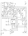
- FIG. 1 shows a circuit for operating a so-called two-pulse electronically commutated motor 20, which has a permanent-magnet rotor 22 and a stator winding, here shown with two phases 24, 26, usually via the iron of the stator (not shown). Laminations are magnetically coupled together.
- Such a motor is therefore called two-pulse, because in the stator winding 24, 26 per rotor rotation of 360 ° el two stator current pulses flow.
- the stator winding may also have only one phase in some cases, and then, during a rotation of 180 ° el, a current pulse flows in one direction, and during the subsequent rotation of 180 ° el, a current pulse flows in the opposite direction.
- a typical example is shown in DE 2346380 C2.
- Such motors are often designed as so-called. Claw pole motors, in which case the claw poles are designed so that they produce a dependent of the rotational position reluctance torque.
- Fig. 1 relates to a circuit according to the sensorless principle, ie without Hall sensor.
- the rotor 22 is shown bipolar, but could also have other numbers of poles.
- 360 ° mech 360 ° el ,
- the motor 20 is controlled by a microcontroller ( ⁇ C) 30 whose Ports are designated 1 to 14. These refer to a ⁇ C of Type PIC16F676. Terminal 1 is connected to a regulated voltage of +5 V, the terminal 14 to ground 32. In between is a capacitor 34th
- the motor 20 is powered by an operating voltage U B with power.
- the positive terminal is indicated at 36, and to it the one terminals 24 ', 26' of the phases 24, 26 are connected. Between the terminal 36 and ground 32 is z. B.
- U B 13 V, ie the voltage of a (not shown) vehicle battery.
- an n-channel MOSFET 40 for controlling the phase 26, an n-channel MOSFET 42.
- the terminal 24 "of the phase 24 is connected to the drain terminal D of the transistor 40, and the terminal 26 "of the phase 26 to the terminal D of the transistor 42.
- the sources S of both transistors are connected to each other and to the drain D of an n-channel MOSFET 44, which serves in the phases 24, 26 a to produce constant total current.
- the source S of the transistor 44 is connected to ground 32 via a resistor 46 for measuring current.
- the voltage u R at the resistor 46 is fed to the input 3 of the ⁇ C 30 via an RC filter element 48, 50.
- the ⁇ C provides at its output 2 a control signal 52 which controls the operating point of the transistor 44 to give the desired constant current which is adjustable by the program of the ⁇ C 30.
- Inexpensive microcontrollers such as those used in motors, usually have no hardware to generate a PWM signal. So you have to have one Generate signal through a program, what the resources of such would largely block the microcontroller.
- the capacitor 56 is first on the resistor 54th charged.
- the transistor 44 operates so that the desired Constant current results, and this is therefore due to the ⁇ C 30 program adjustable.
- the capacitor 56 is charged, the terminal of the ⁇ C 30 becomes switched to high impedance.
- the capacitor 56 discharges, its Charge "refreshed".
- For the ⁇ C 30 usually requires only one clock, so at the given microcontroller 1 ⁇ s
- the transistors 40, 42 are respectively driven by the control transistor 44 in the source region in such a way that the current through the phases 24, 26 is substantially constant at least during the commutation.
- the transistors 40, 42 are operated as so-called. Abschnürstrom provoken. If z. B. the transistor 40 conductively controlled, the control transistor 44 acts as a resistor to ground 32.
- the current through the phase 24, 26 and thus the speed of the motor 20 can thus be by the signal 52, and thus the voltage u 56 on the capacitor 56, adjust.
- control transistor 44 it is achieved that in the transistors 40 and 42, the drain-source voltage U DS is changed, and thus the amount of current through the phases 24 and 26 is affected. In this case, if necessary, it is also achieved that the transistors 40, 42 operate in the pinch-off region. All types of field-effect transistors have such a pinch-off region.
- control transistor 44 If the control transistor 44 is driven so that it has a high resistance and thus has a low conductivity, the potential increases at the Source S of each conductive output stage transistor 40, 42. This flows less current through this transistor and it goes into the pinch-off area.
- control transistor 48 If the control transistor 48 is driven so that it has a low Resistor and thus has a high conductivity, so it is at the Source S of respectively conductive transistor 40 or 42 applied potential low.
- the so connected high gate-source voltage leads to a correspondingly high Amperage in phases 24, 26.
- the transistor 40 is controlled by the output 5 of the ⁇ C 30, the transistor 42 from the output 6.
- the output 5 via a resistor 60 to the gate G of the transistor 40 connected via a resistor 62 to ground 32 and via the series connection of a resistor 64 and a capacitor 66 with the drain D is connected.
- the latter is via a resistor 68 with a Junction 70 connected via a capacitor 72 to ground 32 and is connected via a resistor 74 to the terminal 8 of the ⁇ C 30 (Die Terminals 4, 7, 9 and 11 of the ⁇ C 30 are not connected).
- a voltage u 72 occurs on the capacitor 72, which is used for the determination the direction of rotation of the rotor 22 is used. This will be below described.
- the output 6 is connected to the gate G of the transistor 42 via a resistor 80 connected via a resistor 82 to ground 32 and over the Series connection of a resistor 84 and a capacitor 86 to the drain D is connected.
- the terminal 24 is connected via a capacitor 90 to a node 92 connected via a resistor 94 to ground 32 and via a Resistor 96 is connected to the input 12 of the ⁇ C 30, to which also a Filter capacitor 98 is connected.
- the terminal 26 is via a capacitor 100 with a node 102nd connected via a resistor 104 to ground 32 and via a Resistor 106 is connected to the input 13 of the ⁇ C 30, to which also a Filter capacitor 108 is connected.
- the elements 90 to 108 serve the time at which during a Rotor rotation of the current through the phase 24 or 26 is turned on, with increasing speed towards early shift, which is usually in Based on the terminology of a gasoline engine, as "Zündwinkelverschiebung", although naturally at a Electric motor 20 nothing is ignited.
- a node 114 which is connected via a capacitor 116 to ground 32.
- a voltage U116 which is dependent on the voltage at the terminal 36, occurs at the capacitor 116, and this voltage is supplied via a line 118 to the input 10 of the ⁇ C 30 and serves to eliminate interference voltages that are present in the voltage U72 are included. This will be described below. Preferred values of the components in FIG.
- the motor 20 has a direction of rotation detection 72, 74, are detected with the can, if the engine after a try in the desired Direction of rotation turns. Furthermore, the motor 20 has a controller, namely the ⁇ C 30, with which the current regulator 44 can be set to a desired starting current can, with this current regulator 44 acts on the output stages 40, 42, as above described, so that the motor 20 operated with a constant starting current can be exactly metered according to the requirements.
- the direction of rotation detection 72, 74 makes it possible to start in the wrong direction Recognize direction of rotation and report to the controller 30. This stops then the engine 20 and makes a new start attempt in the right direction.
- Fig. 3 shows over the rotational angle alpha of the rotor 22, the torques T, which occur in a two-pulse motor 20 at start.
- Such a motor has a reluctance torque Trel which, so to speak, is "engineered” into the engine and therefore invariant.
- This torque has for the direction of rotation, which is shown in Fig. 3, a driving, positive part 130 which is relatively short and has a high amplitude.
- T rel has a negative, ie braking, section 132 which has a low amplitude but lasts longer.
- the electromagnetic torque T el is registered, which is driving in the direction shown in FIG. 3 in the manner shown, and thereby overcomes the negative branch 132 of Trel.
- the electromagnetic torque T el has gaps 136 as shown, and these are bridged by the positive branch 130 of T rel , as can be seen in FIG. 3 directly.
- Fig. 4 shows the electromagnetic torque -T el for the run in the reverse direction. In this case, it is supported by branch 132 'of T rel , while it is counteracted by branch 130' of Trel, which is braking here.
- Such a motor 20 thus has a preferred direction, which is shown in Fig. 3, wherein the torques T e l and T rel complement each other very well, and he has a "bad" direction of rotation as shown in FIG. 4, in which the torques T el and T rel very bad match, which is why the start in this direction is difficult. Usually a start in this direction is not required.
- the rotor 22 When starting, the rotor 22 is usually in the position A, because there Trel has the value 0 and this is a stable rest position of the rotor 22.
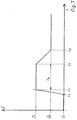
- the current I 1 is maintained during a time Ta, namely between the times t1 and t2, where Ta may for example be between 0.5 and 2 seconds, depending on the size of the motor.
- the current controller 44 sets the current I to a value I 2 corresponding to the desired speed of the motor 20.
- Fig. 6 shows the case where I 2 is greater than I 1 .
- Fig. 7 shows the reverse case where I 2 is less than I 1 . It can be seen that I 1 and the time Ta should be selected according to the requirements of the engine start.
- Fig. 4 shows what happens when the rotor 22 starts in the wrong direction.
- the current I 1 generates a torque -Tel in the opposite direction, which is why this electromagnetic torque -T el drives the rotor 22 in the direction of the arrows 142, with -Tel decreasing in magnitude.
- a resulting total moment T el + T rel is initially negative and causes a small turn against the preferred direction.
- the resulting total torque T el + T rel becomes positive, so that the rotation at the point E comes to a standstill.
- the shape and amplitude of -T el are determined by the constant current I 1 . This is so determined that the torque T el to - be braked in this case - the reluctance torque T rel when starting in the wrong direction can not overcome branch 130 'of the rotor means 22 starts from a point C and reaches a point D At point D, a commutation takes place, ie the current is either switched from phase 24 to phase 26 or vice versa. Thereby, the direction of the electromagnetic torque is switched to + Tel, and there is a positive total torque (T el + T rel ), which causes a rotation in the preferred direction, which is indicated by an arrow 143.
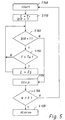
- DIR 1 in S152, it is then checked in S156 whether the time Ta, eg, one second, has already expired. If no, the current is continued with I 1 . If the time Ta has expired, the constant current is switched to I 2 , cf. Fig. 6 and Fig. 7.
- the program goes to S156, where the number N of the Starting attempts is counted. If this is greater than 3, the program goes to S158 and generates an alarm. If N is less than 4 in S156, a new one occurs Start attempt in the right direction.
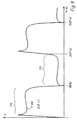
- the determination of the direction of rotation takes place in that one in the Stator winding detected and analyzed during operation induced voltages. This is therefore possible because these voltages depending on the direction of rotation in a motor of the type mentioned have different shapes. This can be the desired information about the direction of rotation of the motor relative to Remove reluctance torque.
- Figs. 8 and 9 are schematic representations, i. in reality, the increase may be in the range of 170 and 173 respectively and the drop in Range 171 or 172 be less strong. For didactic reasons, the Differences exaggerated.
- FIG. 10 shows an excerpt from FIG. 1, namely the essential elements of the measuring circuit for detecting the direction of rotation.
- This potential is supplied to the capacitor 72 via the resistor 68.
- the switch S is opened by the program of the ⁇ C 30, so that the voltage u 72 at the capacitor 72 rises to a value which corresponds approximately to the instantaneous voltage U. This voltage across capacitor 72 is converted to a digital value in an A / D converter 120 and latched.
- FIG. 11 a positive sign of the difference ⁇ results, and in FIG. 12 , a negative sign results, because in the direction of rotation according to FIG. 12, the voltage U in the currentless phase has a falling characteristic according to FIG 11 has an increasing characteristic according to FIG. 8. This is a characteristic of such two-pulse motors, which is utilized in the present case for detecting the direction of rotation.
- control transistor 44 the current in the resistor 46 is kept constant, d. h, the currently energized phase 26 has no significant effect on the voltage u ind at phase 24 at which the measurements take place because the constant current in phase 26 does not cause any transformer coupling to phase 24.
- the absolute measurements measured on the energized string 24 or 26, are additionally used to generate a constant current. If uR below 1 V, it becomes difficult to maintain a constant current.
Landscapes
- Engineering & Computer Science (AREA)
- Power Engineering (AREA)
- Control Of Motors That Do Not Use Commutators (AREA)
- Stopping Of Electric Motors (AREA)
- Control Of Stepping Motors (AREA)
Abstract
Description
- Fig. 1
- ein Schaltbild eines Motors zur Durchführung eines erfindungsgemäßen Verfahrens,
- Fig. 2
- ein Übersichtsschema zur Erläuterung eines erfindungsgemäßen Verfahrens,
- Fig. 3
- eine Darstellung der Drehmomente, die bei einem Motor nach der Erfindung im Betrieb auftreten, wenn sich dieser Motor in der gewünschten Drehrichtung dreht,
- Fig. 4
- eine Darstellung analog Fig. 3, wobei aber die Momente für den Fall dargestellt sind, dass sich der Rotor nicht in der gewünschten Drehrichtung dreht,
- Fig. 5
- ein Flussdiagramm zur Erläuterung eines bevorzugten Verfahrensablaufs,
- Fig. 6
- eine Darstellung der Ströme, wie sie beim Start auftreten können,
- Fig. 7
- eine Darstellung analog Fig. 6, bei welcher der Strom durch den Motor nach dem Start niedriger ist als während des Starts.
- Fig. 8
- die Form der induzierten Spannung für den Betrieb des Motors in seiner bevorzugten Drehrichtung,
- Fig. 9
- die Form der induzierten Spannung für den Betrieb des Motors entgegen seiner bevorzugten Drehrichtung,
- Fig. 10
- ein Prinzipschaltbild zur Erläuterung der Überlegungen, welche der sensorlosen Erfassung der Drehrichtung bei einem Motor dieser Bauart zugrunde liegen,
- Fig. 11
- eine schematische Darstellung der Erfassung der Drehrichtung für DIR = 1, und
- Fig. 12
- eine schematische Darstellung der Erfassung der Drehrichtung für DIR = 0.
| Bevorzugte Werte der Bauelemente in Fig. 1 (für UB = 13 V): | |
| Transistoren 40, 42, 44 | ILRL3410 |
| C72, 116 | 2 nF |
| C50, 66, 86, 98, 108 | 1 nF |
| C34, 56 | 100 nF |
| R62, 68, 82, 94, 96, 104, 106, 112 | 100 kΩ |
| R48, 54, 60, 80 | 10 kΩ |
| R74 | 0Ω |
| R46 | 1,5 Ω |
| R64, 84 | 1 kΩ |
Claims (9)
- Verfahren zum Starten eines elektronisch kommutierten Motors in einer bevorzugten Drehrichtung, welcher Motor einen Stator mit einer Statorwicklungsanordnung (24, 26) und einen permanentmagnetischen Rotor (22) aufweist, welch letzterer bei seiner Drehung durch Interaktion mit dem Stator ein Reluktanz-Hilfsmoment (Trel) erzeugt, das antreibende Abschnitte (130) und bremsende Abschnitte (132) aufweist,
und mit einer Vorrichtung zum Steuern des Stromes in der Statorwicklungsanordnung (24, 26), um ein elektromagnetisches Drehmoment (Tel) zu erzeugen, das pro Rotordrehung von 360° el. zwei antreibende Abschnitte aufweist, wobei benachbarte antreibende Abschnitte jeweils durch eine Lücke (136) getrennt sind,
und bei der Drehung des Rotors (22) in dessen bevorzugter Drehrichtung (Fig. 3: 140) jeweils ein antreibender Abschnitt (130) des Reluktanzmoments (Trel) in der Lücke (136) zwischen zwei antreibenden Abschnitten des elektromagnetischen Drehmoments (Tel) wirksam ist, mit folgenden Schritten:a) Die elektrische Energiezufuhr zum Motor wird in der Weise kontrolliert, dass der Motor bei einem Start in der zur bevorzugten Drehrichtung entgegengesetzten Richtung (Fig. 4: 142) einen in dieser entgegengesetzten Drehrichtung wirksamen bremsenden Abschnitt (Fig. 4: 130`) des Reluktanz-Hilfsmoments (Trel) nicht überwinden kann;b) es wird überwacht, ob sich der Rotor (22) in der gewünschten Drehrichtung dreht. - Verfahren nach Anspruch 1, bei welchem die elektrische Energiezufuhr zum Motor durch Begrenzung des Motorstroms auf einen vorgegebenen Wert (I1) kontrolliert wird.
- Verfahren nach Anspruch 1 oder 2, bei welchem dann, wenn bei der Überwachung festgestellt wird, dass sich der Rotor (22) nicht in der gewünschten Drehrichtung (DIR = 1) dreht, der Motor gestoppt und ein neuer Startversuch unternommen wird.
- Verfahren nach einem der vorhergehenden Ansprüche, bei welchem der Motorstrom im Wesentlichen monoton auf den für den Anlauf gewählten konstanten Wert (I1) erhöht wird.
- Verfahren nach einem der vorhergehenden Ansprüche, bei welchem der konstante Strom (I1) während einer vorgegebenen Zeitspanne (Ta) aufrechterhalten wird.
- Elektromotor, welcher einen Stator mit einer Statorwicklungsanordnung (24, 26) und einen permanentmagnetischen Rotor (22) aufweist, welcher bei seiner Drehung durch Interaktion mit dem Stator ein Reluktanz-Hilfsmoment (Trel) erzeugt, das antreibende Abschnitte (130) und bremsende Abschnitte (132) aufweist,
und mit einer Vorrichtung zum Steuern des Stromes in der Statorwicklungsanordnung (24, 26), um ein elektromagnetisches Drehmoment zu erzeugen, das pro Rotordrehung von 360° el. zwei antreibende Abschnitte aufweist, welche durch eine Lücke getrennt sind, und bei der Drehung des Rotors (22) in dessen bevorzugter Drehrichtung jeweils ein antreibender Abschnitt (130) des Reluktanzmoments (Trel) in der Lücke (136) zwischen zwei antreibenden Abschnitten des elektromagnetischen Drehmoments (Tel) wirksam ist,
welcher Motor zur Ausführung folgender Schritte ausgebildet ist:a) Die Zufuhr von elektrischer Energie zur Statorwicklungsanordnung (24, 26) wird in der Weise kontrolliert, dass der Rotor bei einem Start in der zur bevorzugten Drehrichtung entgegengesetzten Drehrichtung einen in dieser entgegengesetzten Richtung wirksamen bremsenden Abschnitt (Fig. 4: 130') des Reluktanzmoments (Trel) nicht überwinden kann;b) es wird überwacht, ob sich der Rotor (22) in der gewünschten Drehrichtung dreht. - Motor nach Anspruch 6, welcher eine Strombegrenzungsanordnung aufweist, bei der der Wert für die Strombegrenzung einstellbar ist.
- Motor nach Anspruch 7, welcher einen Mikrocontroller (30), eine Strommessvorrichtung (46) und einen Abschnür-Strombegrenzer (44) aufweist,
und bei welchem der Strom-Grenzwert des Abschnür-Strombegrenzers durch ein Ausgangssignal (52) des Mikrocontrollers (30) steuerbar ist. - Motor nach Anspruch 8, bei welchem der Abschnür-Strombegrenzer einen MOSFET (44) aufweist, dessen Strom-Grenzwert von der Ladespannung (u56) eines Kondensators (56) abhängig ist, dessen Ladung ihrerseits vom Mikrocontroller (30) beeinflussbar ist.
Applications Claiming Priority (2)
| Application Number | Priority Date | Filing Date | Title |
|---|---|---|---|
| DE102004024638 | 2004-05-12 | ||
| DE102004024638 | 2004-05-12 |
Publications (2)
| Publication Number | Publication Date |
|---|---|
| EP1601095A1 true EP1601095A1 (de) | 2005-11-30 |
| EP1601095B1 EP1601095B1 (de) | 2007-08-29 |
Family
ID=34936070
Family Applications (1)
| Application Number | Title | Priority Date | Filing Date |
|---|---|---|---|
| EP05009657A Expired - Lifetime EP1601095B1 (de) | 2004-05-12 | 2005-05-03 | Elektronisch kommutierter zweipulsiger Motor und Verfahren zum Starten eines solchen Motors |
Country Status (4)
| Country | Link |
|---|---|
| US (1) | US20050253545A1 (de) |
| EP (1) | EP1601095B1 (de) |
| AT (1) | ATE371984T1 (de) |
| DE (1) | DE502005001351D1 (de) |
Families Citing this family (3)
| Publication number | Priority date | Publication date | Assignee | Title |
|---|---|---|---|---|
| US7211984B2 (en) * | 2004-11-09 | 2007-05-01 | General Motors Corporation | Start-up and restart of interior permanent magnet machines |
| DE102010030239A1 (de) * | 2010-06-17 | 2011-12-22 | BSH Bosch und Siemens Hausgeräte GmbH | Verfahren und Vorrichtung zum Anlassen eines Elektromotors |
| DE102021110687A1 (de) * | 2021-04-27 | 2022-10-27 | Bühler Motor GmbH | Verfahren zum Anlaufen eines Rotors eines Klauenpolmotors |
Citations (5)
| Publication number | Priority date | Publication date | Assignee | Title |
|---|---|---|---|---|
| DE2346380A1 (de) * | 1973-05-23 | 1974-11-28 | Papst Motoren Kg | Kollektorloser gleichstrommotor |
| DE4438569A1 (de) * | 1994-10-28 | 1996-05-02 | Bosch Gmbh Robert | Verfahren und Schaltungsanordnung zum Anfahren eines elektronisch kommutierten, einständigen Gleichstrommotors |
| EP1104950A2 (de) * | 1999-11-27 | 2001-06-06 | Papst-Motoren GmbH & Co. KG | Elektronisch kommutierter Gleichstrommotor |
| EP1213829A1 (de) * | 1996-01-10 | 2002-06-12 | Papst-Motoren GmbH & Co. KG | Verfahren zum Betreiben eines elektronisch kommutierten Gleichstrommotors, und Motor zur Durchführung eines solchen Verfahrens |
| DE10235293A1 (de) * | 2001-08-10 | 2003-02-27 | Papst Motoren Gmbh & Co Kg | Verfahren zur Steuerung der Kommutierung bei einem elektronisch kommutierenden Motor, und elektronisch kommutierter Motor zur Durchführung eines solchen Verfahrens |
Family Cites Families (16)
| Publication number | Priority date | Publication date | Assignee | Title |
|---|---|---|---|---|
| US4119895A (en) * | 1976-04-12 | 1978-10-10 | Papst-Motoren Kg | Brushless d.c. motor with precise speed control |
| USRE37360E1 (en) * | 1985-09-16 | 2001-09-11 | Fisher & Paykel | Electronic motor controls, laundry machines including such controls and/or methods of operating such controls |
| US4673849A (en) * | 1986-10-10 | 1987-06-16 | Allied Corporation | Permanent magnet motor closed loop restarting system |
| US4839754A (en) * | 1987-02-26 | 1989-06-13 | Micropolis Corporation | Winchester disk drive motor circuitry |
| US5012166A (en) * | 1989-01-18 | 1991-04-30 | Hitachi, Ltd. | Control system for brushless DC motor |
| US5485047A (en) * | 1992-01-27 | 1996-01-16 | Kabushikigaisha Sekogiken | Reluctance-type motor and a rotor for a reluctance-type high-speed motor |
| US5670852A (en) * | 1994-01-18 | 1997-09-23 | Micropump, Inc. | Pump motor and motor control |
| EP0837553B1 (de) * | 1996-10-18 | 2001-11-14 | Papst-Motoren GmbH & Co. KG | Ansteuerschaltung für einen bürstenlosen Gleichstrommotor |
| DE19815425A1 (de) * | 1998-04-07 | 1999-10-14 | Bosch Gmbh Robert | Verfahren und Vorrichtung zur Ansteuerung eines elektronisch kommutierten Mehrphasen-Gleichstrommotors |
| JP2000287477A (ja) * | 1999-03-29 | 2000-10-13 | Mitsubishi Electric Corp | モータ駆動装置 |
| DE19955247A1 (de) * | 1999-11-17 | 2001-05-31 | Bosch Gmbh Robert | Verfahren zum Anfahren eines sensor- und bürstenlosen Gleichstrommotors |
| JP3673964B2 (ja) * | 2000-03-29 | 2005-07-20 | 株式会社ルネサステクノロジ | ブラシレスモータ駆動制御用半導体集積回路およびブラシレスモータ駆動制御装置 |
| US6437535B1 (en) * | 2000-09-25 | 2002-08-20 | General Electric Company | Starting system and method for a microturbine power generation unit |
| US6647325B2 (en) * | 2001-02-19 | 2003-11-11 | Kokusan Denki Co., Ltd. | Control system for electric motor for driving electric vehicle |
| US6731086B2 (en) * | 2001-04-26 | 2004-05-04 | Rohm Co., Ltd. | Motor driving device |
| US6864653B2 (en) * | 2001-11-26 | 2005-03-08 | Ebm-Papst St. Georgen Gmbh & Co. Kg | Equipment fan |
-
2005
- 2005-05-03 EP EP05009657A patent/EP1601095B1/de not_active Expired - Lifetime
- 2005-05-03 AT AT05009657T patent/ATE371984T1/de not_active IP Right Cessation
- 2005-05-03 DE DE502005001351T patent/DE502005001351D1/de not_active Expired - Lifetime
- 2005-05-11 US US11/127,872 patent/US20050253545A1/en not_active Abandoned
Patent Citations (5)
| Publication number | Priority date | Publication date | Assignee | Title |
|---|---|---|---|---|
| DE2346380A1 (de) * | 1973-05-23 | 1974-11-28 | Papst Motoren Kg | Kollektorloser gleichstrommotor |
| DE4438569A1 (de) * | 1994-10-28 | 1996-05-02 | Bosch Gmbh Robert | Verfahren und Schaltungsanordnung zum Anfahren eines elektronisch kommutierten, einständigen Gleichstrommotors |
| EP1213829A1 (de) * | 1996-01-10 | 2002-06-12 | Papst-Motoren GmbH & Co. KG | Verfahren zum Betreiben eines elektronisch kommutierten Gleichstrommotors, und Motor zur Durchführung eines solchen Verfahrens |
| EP1104950A2 (de) * | 1999-11-27 | 2001-06-06 | Papst-Motoren GmbH & Co. KG | Elektronisch kommutierter Gleichstrommotor |
| DE10235293A1 (de) * | 2001-08-10 | 2003-02-27 | Papst Motoren Gmbh & Co Kg | Verfahren zur Steuerung der Kommutierung bei einem elektronisch kommutierenden Motor, und elektronisch kommutierter Motor zur Durchführung eines solchen Verfahrens |
Also Published As
| Publication number | Publication date |
|---|---|
| US20050253545A1 (en) | 2005-11-17 |
| EP1601095B1 (de) | 2007-08-29 |
| ATE371984T1 (de) | 2007-09-15 |
| DE502005001351D1 (de) | 2007-10-11 |
Similar Documents
| Publication | Publication Date | Title |
|---|---|---|
| EP1596495B1 (de) | Verfahren zum sensorlosen Betrieb eines elektronisch kommutierten Motors, und Motor zur Durchführung eines solchen Verfahrens | |
| EP0895345B1 (de) | Verfahren zur Überwachung eines kollektorlosen Gleichstrommotors, und Motor zur Durchführung eines solchen Verfahrens | |
| DE112007001630B4 (de) | Verfahren und Vorrichtung zur Bestimmung der Rotorposition bei einem bürstenlosen und sensorlosen Elektromotor | |
| DE10355651B4 (de) | Verfahren zur Optimierung des Wirkungsgrades eines unter Last betriebenen Motors | |
| EP1727268A2 (de) | Verfahren zum Betrieben eines elektronisch kommutierten Motors, und Motor zur Durchführung eines solchen Verfahrens | |
| EP2603971B1 (de) | Elektronisch kommutierter motor | |
| WO2008148401A1 (de) | Verfahren zum betrieb eines einsträngigen elektronisch kommutierten motors an einer gleichspannungsquelle, und motor zur durchführung eines solchen verfahrens | |
| DE10246382A1 (de) | Verfahren zum Betreiben eines elektronisch kommutierten Motors, und Motor zur Durchführung eines solchen Verfahrens | |
| EP1535388B1 (de) | Verfahren und Vorrichtung zur Drehzahlregelung eines mit Hilfsmoment arbeitenden zweipulsigen Motors | |
| DE10326606A1 (de) | Verfahren zur Kommutierung eines bürstenlosen Gleichstrommotors | |
| WO2003015255A1 (de) | Verfahren zur steuerung der kommutierung bei einem elektronisch kommutierten motor, und elektronisch kommutierter motor zur durchführung eines solchen verfahrens | |
| EP2278339B1 (de) | System mit einem einphasigen, elektronisch kommutierten Motor und elektronischer Recheneinheit | |
| WO2012025904A2 (de) | Verfahren zum ansteuern eines einphasigen bldc kleinmotors | |
| EP2343797B1 (de) | Einphasiger elektronisch kommutierter Motor | |
| WO2008034670A1 (de) | Verfahren zum betreiben eines elektronisch kommutierenden elektromotors | |
| DE102014107949A1 (de) | Verfahren und Vorrichtung zur Erkennung eines Nulldurchgangs eines Stroms durch einen Strang eines bürstenlosen Gleichstrom- motors | |
| EP1107441A2 (de) | Elektronisch kommunierter Gleichstrommotor | |
| EP1601095B1 (de) | Elektronisch kommutierter zweipulsiger Motor und Verfahren zum Starten eines solchen Motors | |
| DE102016222015A1 (de) | Elektrischer Antrieb und Verfahren zum Betrieb eines Elektromotors | |
| DE60302755T2 (de) | Verfahren und System zur Bestimmung für die elektronische Kommutierung in bürstenloser Gleichstrommaschine unabhängig von der Postionierung des Rotorlagesensors | |
| EP1443635B1 (de) | Verfahren zum Steuern des Zündwinkels und einphasiger wechselstromversorgter Elektromotor | |
| EP2338223A2 (de) | Gleichstrommotor und verfahren zum betreiben des gleichstrommotors | |
| DE102005020736A1 (de) | Verfahren zum Starten eines elektronisch kommutierten zweipulsigen Motors | |
| DE102017127410A1 (de) | Verfahren und Schaltungsanordnung zur Ermittlung der Stellung eines Rotors eines Elektromotors | |
| DE102005007995A1 (de) | Rotorlagendetektion |
Legal Events
| Date | Code | Title | Description |
|---|---|---|---|
| PUAI | Public reference made under article 153(3) epc to a published international application that has entered the european phase |
Free format text: ORIGINAL CODE: 0009012 |
|
| AK | Designated contracting states |
Kind code of ref document: A1 Designated state(s): AT BE BG CH CY CZ DE DK EE ES FI FR GB GR HU IE IS IT LI LT LU MC NL PL PT RO SE SI SK TR |
|
| AX | Request for extension of the european patent |
Extension state: AL BA HR LV MK YU |
|
| 17P | Request for examination filed |
Effective date: 20051008 |
|
| AKX | Designation fees paid |
Designated state(s): AT BE BG CH CY CZ DE DK EE ES FI FR GB GR HU IE IS IT LI LT LU MC NL PL PT RO SE SI SK TR |
|
| GRAP | Despatch of communication of intention to grant a patent |
Free format text: ORIGINAL CODE: EPIDOSNIGR1 |
|
| RTI1 | Title (correction) |
Free format text: ELECTRONICALLY COMMUTATED TWO-PULSE MOTOR AND METHOD FOR STARTING SUCH A MOTOR |
|
| GRAS | Grant fee paid |
Free format text: ORIGINAL CODE: EPIDOSNIGR3 |
|
| GRAA | (expected) grant |
Free format text: ORIGINAL CODE: 0009210 |
|
| AK | Designated contracting states |
Kind code of ref document: B1 Designated state(s): AT BE BG CH CY CZ DE DK EE ES FI FR GB GR HU IE IS IT LI LT LU MC NL PL PT RO SE SI SK TR |
|
| REG | Reference to a national code |
Ref country code: GB Ref legal event code: FG4D Free format text: NOT ENGLISH |
|
| REG | Reference to a national code |
Ref country code: CH Ref legal event code: EP |
|
| REG | Reference to a national code |
Ref country code: IE Ref legal event code: FG4D Free format text: LANGUAGE OF EP DOCUMENT: GERMAN |
|
| REF | Corresponds to: |
Ref document number: 502005001351 Country of ref document: DE Date of ref document: 20071011 Kind code of ref document: P |
|
| GBT | Gb: translation of ep patent filed (gb section 77(6)(a)/1977) |
Effective date: 20071121 |
|
| PG25 | Lapsed in a contracting state [announced via postgrant information from national office to epo] |
Ref country code: IS Free format text: LAPSE BECAUSE OF FAILURE TO SUBMIT A TRANSLATION OF THE DESCRIPTION OR TO PAY THE FEE WITHIN THE PRESCRIBED TIME-LIMIT Effective date: 20071229 Ref country code: LT Free format text: LAPSE BECAUSE OF FAILURE TO SUBMIT A TRANSLATION OF THE DESCRIPTION OR TO PAY THE FEE WITHIN THE PRESCRIBED TIME-LIMIT Effective date: 20070829 Ref country code: ES Free format text: LAPSE BECAUSE OF FAILURE TO SUBMIT A TRANSLATION OF THE DESCRIPTION OR TO PAY THE FEE WITHIN THE PRESCRIBED TIME-LIMIT Effective date: 20071210 Ref country code: FI Free format text: LAPSE BECAUSE OF FAILURE TO SUBMIT A TRANSLATION OF THE DESCRIPTION OR TO PAY THE FEE WITHIN THE PRESCRIBED TIME-LIMIT Effective date: 20070829 Ref country code: NL Free format text: LAPSE BECAUSE OF FAILURE TO SUBMIT A TRANSLATION OF THE DESCRIPTION OR TO PAY THE FEE WITHIN THE PRESCRIBED TIME-LIMIT Effective date: 20070829 |
|
| NLV1 | Nl: lapsed or annulled due to failure to fulfill the requirements of art. 29p and 29m of the patents act | ||
| PG25 | Lapsed in a contracting state [announced via postgrant information from national office to epo] |
Ref country code: PL Free format text: LAPSE BECAUSE OF FAILURE TO SUBMIT A TRANSLATION OF THE DESCRIPTION OR TO PAY THE FEE WITHIN THE PRESCRIBED TIME-LIMIT Effective date: 20070829 |
|
| REG | Reference to a national code |
Ref country code: IE Ref legal event code: FD4D |
|
| ET | Fr: translation filed | ||
| PG25 | Lapsed in a contracting state [announced via postgrant information from national office to epo] |
Ref country code: DK Free format text: LAPSE BECAUSE OF FAILURE TO SUBMIT A TRANSLATION OF THE DESCRIPTION OR TO PAY THE FEE WITHIN THE PRESCRIBED TIME-LIMIT Effective date: 20070829 Ref country code: GR Free format text: LAPSE BECAUSE OF FAILURE TO SUBMIT A TRANSLATION OF THE DESCRIPTION OR TO PAY THE FEE WITHIN THE PRESCRIBED TIME-LIMIT Effective date: 20071130 |
|
| PG25 | Lapsed in a contracting state [announced via postgrant information from national office to epo] |
Ref country code: SK Free format text: LAPSE BECAUSE OF FAILURE TO SUBMIT A TRANSLATION OF THE DESCRIPTION OR TO PAY THE FEE WITHIN THE PRESCRIBED TIME-LIMIT Effective date: 20070829 Ref country code: CZ Free format text: LAPSE BECAUSE OF FAILURE TO SUBMIT A TRANSLATION OF THE DESCRIPTION OR TO PAY THE FEE WITHIN THE PRESCRIBED TIME-LIMIT Effective date: 20070829 Ref country code: PT Free format text: LAPSE BECAUSE OF FAILURE TO SUBMIT A TRANSLATION OF THE DESCRIPTION OR TO PAY THE FEE WITHIN THE PRESCRIBED TIME-LIMIT Effective date: 20080129 Ref country code: IE Free format text: LAPSE BECAUSE OF FAILURE TO SUBMIT A TRANSLATION OF THE DESCRIPTION OR TO PAY THE FEE WITHIN THE PRESCRIBED TIME-LIMIT Effective date: 20070829 |
|
| PG25 | Lapsed in a contracting state [announced via postgrant information from national office to epo] |
Ref country code: RO Free format text: LAPSE BECAUSE OF FAILURE TO SUBMIT A TRANSLATION OF THE DESCRIPTION OR TO PAY THE FEE WITHIN THE PRESCRIBED TIME-LIMIT Effective date: 20070829 Ref country code: SE Free format text: LAPSE BECAUSE OF FAILURE TO SUBMIT A TRANSLATION OF THE DESCRIPTION OR TO PAY THE FEE WITHIN THE PRESCRIBED TIME-LIMIT Effective date: 20071129 |
|
| PLBE | No opposition filed within time limit |
Free format text: ORIGINAL CODE: 0009261 |
|
| STAA | Information on the status of an ep patent application or granted ep patent |
Free format text: STATUS: NO OPPOSITION FILED WITHIN TIME LIMIT |
|
| 26N | No opposition filed |
Effective date: 20080530 |
|
| BERE | Be: lapsed |
Owner name: EBM-PAPST ST. GEORGEN G.M.B.H. & CO. KG Effective date: 20080531 |
|
| PG25 | Lapsed in a contracting state [announced via postgrant information from national office to epo] |
Ref country code: MC Free format text: LAPSE BECAUSE OF NON-PAYMENT OF DUE FEES Effective date: 20080531 |
|
| PG25 | Lapsed in a contracting state [announced via postgrant information from national office to epo] |
Ref country code: EE Free format text: LAPSE BECAUSE OF FAILURE TO SUBMIT A TRANSLATION OF THE DESCRIPTION OR TO PAY THE FEE WITHIN THE PRESCRIBED TIME-LIMIT Effective date: 20070829 |
|
| PG25 | Lapsed in a contracting state [announced via postgrant information from national office to epo] |
Ref country code: BE Free format text: LAPSE BECAUSE OF NON-PAYMENT OF DUE FEES Effective date: 20080531 |
|
| PG25 | Lapsed in a contracting state [announced via postgrant information from national office to epo] |
Ref country code: SI Free format text: LAPSE BECAUSE OF FAILURE TO SUBMIT A TRANSLATION OF THE DESCRIPTION OR TO PAY THE FEE WITHIN THE PRESCRIBED TIME-LIMIT Effective date: 20070829 |
|
| PG25 | Lapsed in a contracting state [announced via postgrant information from national office to epo] |
Ref country code: CY Free format text: LAPSE BECAUSE OF FAILURE TO SUBMIT A TRANSLATION OF THE DESCRIPTION OR TO PAY THE FEE WITHIN THE PRESCRIBED TIME-LIMIT Effective date: 20070829 |
|
| PG25 | Lapsed in a contracting state [announced via postgrant information from national office to epo] |
Ref country code: AT Free format text: LAPSE BECAUSE OF NON-PAYMENT OF DUE FEES Effective date: 20080503 Ref country code: BG Free format text: LAPSE BECAUSE OF FAILURE TO SUBMIT A TRANSLATION OF THE DESCRIPTION OR TO PAY THE FEE WITHIN THE PRESCRIBED TIME-LIMIT Effective date: 20071129 |
|
| REG | Reference to a national code |
Ref country code: CH Ref legal event code: PL |
|
| PG25 | Lapsed in a contracting state [announced via postgrant information from national office to epo] |
Ref country code: CH Free format text: LAPSE BECAUSE OF NON-PAYMENT OF DUE FEES Effective date: 20090531 Ref country code: LI Free format text: LAPSE BECAUSE OF NON-PAYMENT OF DUE FEES Effective date: 20090531 |
|
| PG25 | Lapsed in a contracting state [announced via postgrant information from national office to epo] |
Ref country code: HU Free format text: LAPSE BECAUSE OF FAILURE TO SUBMIT A TRANSLATION OF THE DESCRIPTION OR TO PAY THE FEE WITHIN THE PRESCRIBED TIME-LIMIT Effective date: 20080301 Ref country code: LU Free format text: LAPSE BECAUSE OF NON-PAYMENT OF DUE FEES Effective date: 20080503 |
|
| PG25 | Lapsed in a contracting state [announced via postgrant information from national office to epo] |
Ref country code: TR Free format text: LAPSE BECAUSE OF FAILURE TO SUBMIT A TRANSLATION OF THE DESCRIPTION OR TO PAY THE FEE WITHIN THE PRESCRIBED TIME-LIMIT Effective date: 20070829 |
|
| REG | Reference to a national code |
Ref country code: FR Ref legal event code: PLFP Year of fee payment: 12 |
|
| PGFP | Annual fee paid to national office [announced via postgrant information from national office to epo] |
Ref country code: IT Payment date: 20160330 Year of fee payment: 12 |
|
| REG | Reference to a national code |
Ref country code: FR Ref legal event code: PLFP Year of fee payment: 13 |
|
| REG | Reference to a national code |
Ref country code: DE Ref legal event code: R084 Ref document number: 502005001351 Country of ref document: DE |
|
| REG | Reference to a national code |
Ref country code: FR Ref legal event code: PLFP Year of fee payment: 14 |
|
| PG25 | Lapsed in a contracting state [announced via postgrant information from national office to epo] |
Ref country code: IT Free format text: LAPSE BECAUSE OF NON-PAYMENT OF DUE FEES Effective date: 20170503 |
|
| REG | Reference to a national code |
Ref country code: DE Ref legal event code: R084 Ref document number: 502005001351 Country of ref document: DE Ref country code: DE Ref legal event code: R085 Ref document number: 502005001351 Country of ref document: DE |
|
| REG | Reference to a national code |
Ref country code: GB Ref legal event code: 732E Free format text: REGISTERED BETWEEN 20230622 AND 20230628 |
|
| PGFP | Annual fee paid to national office [announced via postgrant information from national office to epo] |
Ref country code: FR Payment date: 20230517 Year of fee payment: 19 Ref country code: DE Payment date: 20230519 Year of fee payment: 19 |
|
| P01 | Opt-out of the competence of the unified patent court (upc) registered |
Effective date: 20230726 |
|
| PGFP | Annual fee paid to national office [announced via postgrant information from national office to epo] |
Ref country code: GB Payment date: 20230522 Year of fee payment: 19 |
|
| REG | Reference to a national code |
Ref country code: DE Ref legal event code: R119 Ref document number: 502005001351 Country of ref document: DE |
|
| GBPC | Gb: european patent ceased through non-payment of renewal fee |
Effective date: 20240503 |
|
| PG25 | Lapsed in a contracting state [announced via postgrant information from national office to epo] |
Ref country code: DE Free format text: LAPSE BECAUSE OF NON-PAYMENT OF DUE FEES Effective date: 20241203 |
|
| PG25 | Lapsed in a contracting state [announced via postgrant information from national office to epo] |
Ref country code: FR Free format text: LAPSE BECAUSE OF NON-PAYMENT OF DUE FEES Effective date: 20240531 |
|
| PG25 | Lapsed in a contracting state [announced via postgrant information from national office to epo] |
Ref country code: GB Free format text: LAPSE BECAUSE OF NON-PAYMENT OF DUE FEES Effective date: 20240503 |