EP1600992A1 - Electromagnetic relay - Google Patents
Electromagnetic relay Download PDFInfo
- Publication number
- EP1600992A1 EP1600992A1 EP05011227A EP05011227A EP1600992A1 EP 1600992 A1 EP1600992 A1 EP 1600992A1 EP 05011227 A EP05011227 A EP 05011227A EP 05011227 A EP05011227 A EP 05011227A EP 1600992 A1 EP1600992 A1 EP 1600992A1
- Authority
- EP
- European Patent Office
- Prior art keywords
- movable
- spring
- electromagnetic relay
- plate
- fixed
- Prior art date
- Legal status (The legal status is an assumption and is not a legal conclusion. Google has not performed a legal analysis and makes no representation as to the accuracy of the status listed.)
- Withdrawn
Links
- 229920006015 heat resistant resin Polymers 0.000 claims abstract description 8
- XEEYBQQBJWHFJM-UHFFFAOYSA-N Iron Chemical group [Fe] XEEYBQQBJWHFJM-UHFFFAOYSA-N 0.000 claims description 21
- 239000011810 insulating material Substances 0.000 claims description 16
- 239000000919 ceramic Substances 0.000 claims description 6
- 239000002131 composite material Substances 0.000 claims description 6
- 239000011521 glass Substances 0.000 claims description 6
- 239000000463 material Substances 0.000 claims description 6
- 239000011435 rock Substances 0.000 claims description 5
- 238000003825 pressing Methods 0.000 claims description 3
- 230000035939 shock Effects 0.000 abstract description 5
- 238000010586 diagram Methods 0.000 description 6
- 229910000881 Cu alloy Inorganic materials 0.000 description 2
- 239000004020 conductor Substances 0.000 description 2
- 238000004519 manufacturing process Methods 0.000 description 2
- 230000009467 reduction Effects 0.000 description 2
- 230000002159 abnormal effect Effects 0.000 description 1
- 230000000703 anti-shock Effects 0.000 description 1
- 230000008878 coupling Effects 0.000 description 1
- 238000010168 coupling process Methods 0.000 description 1
- 238000005859 coupling reaction Methods 0.000 description 1
- 230000007423 decrease Effects 0.000 description 1
- 238000006073 displacement reaction Methods 0.000 description 1
- 239000000446 fuel Substances 0.000 description 1
- 230000001771 impaired effect Effects 0.000 description 1
- 230000006872 improvement Effects 0.000 description 1
- 238000000034 method Methods 0.000 description 1
- 238000011017 operating method Methods 0.000 description 1
- 230000004044 response Effects 0.000 description 1
- 238000004904 shortening Methods 0.000 description 1
Images


Classifications
-
- H—ELECTRICITY
- H01—ELECTRIC ELEMENTS
- H01H—ELECTRIC SWITCHES; RELAYS; SELECTORS; EMERGENCY PROTECTIVE DEVICES
- H01H50/00—Details of electromagnetic relays
- H01H50/54—Contact arrangements
- H01H50/546—Contact arrangements for contactors having bridging contacts
Definitions
- the present invention relates to an electromagnetic relay and more particularly to the electromagnetic relay being suitable for control of a vehicle-mounted three-phase brushless motor.
- an operating method of power steering for an automobile is changing from a hydraulic type to an electric type with the aim of improving automobile fuel consumption.
- a steering method for controlling a DC (Direct Current) motor is used in electric power steering systems in most cases.
- electric power steering systems using a three-phase brushless motor increases as its application of electric power steering to an automobile having a large piston displacement increases.
- a switching device that can control three phases simultaneously or that can control only two phases out of three phases becomes necessary.
- an electromagnetic relay is becoming very useful which can simultaneously control three phases at a midpoint (connection point) of star connection or can control only two phases.
- Prerequisites to the control of the electric power steering by the electromagnetic relay are a large current-carrying capability (which allows a current of, for example, 100A to flow) and an interrupting capability (which can interrupt a voltage and a current of, for example, 100A at 14V.) to provide torque for the motor. Additionally, in response to a high rate at which components are made electrical and electronic in an automobile, it is required that the electromagnetic relay is miniaturized further.
- a conventional electromagnetic relay is disclosed in Japanese Patent Application Laid-open No. 2002-329447 in which a vehicle-mounted electromagnetic relay can be so configured as to be smaller in size.
- a single electromagnetic relay has not yet been known which has a current-carrying capability (which allows a current of, for example, 100A to flow) and an interrupting capability (which can interrupt a voltage and a current of, for example, 100A at 14V) being large enough for one electromagnetic relay to be able to control one three-phase brushless motor for electric power steering.
- an electromagnetic relay designed to control the three-phase brushless motor is of a type having only one circuit with one ordinarily-open contact (which is called "1 FORM A-type").
- One electromagnetic relay is used in each of, at least, two circuits out of three circuits to be used for control of the three-phase brushless motor or a plurality of electromagnetic relays is used, in order to divide a current within the one circuit to be used for the control of the three-phase brushless motor, depending on a performance capability of the electromagnetic relay.
- a present state is that the electromagnetic relay to be mounted on an automobile requires further miniaturization of its components, further improvement of accuracy in assembling the components, and further increases in productivity of the components, and cost reduction in the components.
- a single electromagnetic relay has two or more circuits each having the ordinarily-open contact, and a ratio of the single electromagnetic relay to occupy a space within a device using electrical and electronic components is smaller than a ratio of a plurality of electromagnetic relays, each having one circuit with one ordinarily-open contact, to occupy a space within the device using electrical and electronic components.
- an electromagnetic relay as described above, it is necessary that the ordinarily-open contact between the two circuits is kept in an insulated state and that an insulating member called a "card" is inserted between the two circuits.
- an object of the present invention to provide an electromagnetic relay which is small in size and is capable of controlling two circuits each having one ordinarily-open contact and of having a large current-carrying capacity and high interrupting capability and being excellent in resistance against shock and vibration.
- an electromagnetic relay including:
- a preferable mode is one that wherein includes:
- a preferable mode is one wherein the movable contactor spring is bow-shaped.
- a preferable mode is one wherein the movable contactor is made of a thick plate.
- a preferable mode is one wherein the movable contactor spring is attached in a center of the movable contactor.
- a preferable mode is one wherein, in a portion in which the ⁇ -shaped holding frames face each other is placed added portions being approximately orthogonal to surfaces including the ⁇ -shaped portion.
- each of the pair of release springs includes a first plate-like spring and a second plate-like spring and the first plate-like spring is attached in a fixed form to one arm portion of each of the ⁇ -shaped holding frames and the second plate-like spring is attached in a fixed form to another arm portion of each of the ⁇ -shaped holding frames and the first plate-like spring and the second plate-like spring are arranged in parallel and in a direction being reverse to each other.
- a preferable mode is one wherein one end of the first plate-like spring is supported in a fixed manner on the insulating material for the base and one end of the second plate-like spring is supported in a movable manner while being slid on a surface of the insulating material for the base.
- a preferable mode is one wherein a width of the first plate-like spring is larger than that of the second plate-like spring.
- a preferable mode is one wherein a length of the first plate-like spring is larger than that of the second plate.
- a preferable mode is one wherein the release spring is formed integrally with the movable contactor spring.
- a preferable mode is one wherein a position used to transfer a movement of the contactor to the card block is deviated to a side of one end of the second plate-like spring, on which a pair of movable supporting points is located, relative to a center point of the card block.
- a preferable mode is one wherein one end of a supporting terminal to fix the electro-magnet block to a base block is fixed to the L-shaped yoke and another end of the supporting terminal is inserted into the base block by pressing and in a fixed manner.
- a preferable mode is one wherein the insulating material for connection is made of a highly heat-resistant resin, ceramic, glass, or composite of these materials.
- the movable contact accommodates deviations in height between the contacts and stable contacting force can be applied between the two ordinarily-open contacts.
- the holding frame that can withstand restoring force of the attached contact spring (movable contact) and release spring can be constructed.
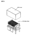
- Figure 1 is a perspective view of an electromagnetic relay according to a preferable embodiment of the present invention.
- Figure 2 is an exploded perspective view of a main body 101 of the electromagnetic relay according to the same embodiment.
- Figure 3 is an exploded perspective view of an electro-magnet block 103 according to the same embodiment.
- Figure 4 is an exploded perspective view of a card block 104 according to the same embodiment.
- Figure 5 is an exploded perspective view of a base block 105 according to the same embodiment.
- Figure 6 is a diagram illustrating a circuit and terminals of the electromagnetic relay. In Fig. 6, terminals 161 and 166 are connected to a coil, terminals 162 and 165 are connected to a first ordinarily-open contact, and terminals 163 and 164 are connected to a second ordinarily-open contact.
- the electromagnetic relay according to the embodiment is made up of the main body (the electromagnetic relay proper) 101 and a cover 102 used to cover the main body (the electromagnetic relay proper) 101.
- the electromagnetic relay according to the embodiment, as shown in Fig. 2 includes the electro-magnet block 103, the card block 104, and the base block 105.
- the electro-magnet block 103 is made up of a coil 106, an iron core 107, a spool 108, a coil block 110 having bundle terminals 109, a yoke 111, an armature 112, a hinge spring 113, and supporting terminals 114.
- the electro-magnet block 103 includes the iron core 106 around which a coil is wound, the L-shaped yoke 111 being attached to one end of the iron core 106, the approximately ⁇ - shaped armature 112 that is placed in a position being opposite to another end of the iron core 106 and is attracted by the energized iron core 106, and the hinge spring 113 that supports the armature 112 in such a manner that the armature 112 is capable of rocking or swinging;
- the card block 104 includes, as shown in Fig. 4, a card 116 having a pair of ⁇ -shaped holding frame 115 electrically separated and being mechanically connected by an insulating material such as a highly heat-resistant resin, ceramic, glass, or composite of these materials, a pair of movable contactors 118 to each of which two movable contacts 117 are joined, a pair of movable contactor springs 119 being joined to the ⁇ -shaped holding frames 115, and a pair of release springs 120 to return the movable contactors 118 from an operating state to a released state.
- an insulating material such as a highly heat-resistant resin, ceramic, glass, or composite of these materials
- a pair of movable contactors 118 to each of which two movable contacts 117 are joined
- a pair of movable contactor springs 119 being joined to the ⁇ -shaped holding frames 115
- a pair of release springs 120 to return the movable contactors 118 from an operating state to
- the base block 105 is constructed so as to integrally form four fixed terminals 122 to which fixed contacts 121 are attached in a fixed manner and two coil terminals 123 using a highly heat-resistant resin.
- the four movable contacts 117 of the card block 104 are placed approximately in one plane, and the four fixed contacts 121 each are placed in positions facing a corresponding one of the four movable contacts 117 on the base block 105, and the four movable contacts 117 and four fixed contacts 121 are simultaneously opened and closed in synchronization with the rock or swing of the armature 112.
- the movable contactor springs 119 are bow-shaped with the thick-plate shaped movable contactors 118 being attached thereto in its central portion in a fixed manner.
- the movable contactor springs 119 are affixed to the holding frame 115.
- a part (an added portion being placed orthogonal approximately to a ⁇ -shaped(C-shaped) surface) of the holding frame 115 being bent in an L-shaped form in a highly heat-resistant resin, ceramic, glass, or composite of these materials is integrally formed and, therefore, tilt deformation of the card 116 caused by contacting force occurring at time of operations can be suppressed.
- the release springs 120 are plate-shaped rectangular springs being bent slightly in their center portions and are attached to the holding frame 115 and may be formed integrally with the movable contactor springs 119 to reduce component counts.
- the two release springs 120 are placed in parallel in a direction being reverse to each other and cross each other when seen from a side and make up one set as a whole.
- One of the two release springs 120 is supported by the base block 105 in a fixed manner and another is supported on the base bock 105 in a movable manner.
- another one set of the release springs 120 is placed around the card 116 in a manner being symmetric with respect to a line.
- each of the fixed terminals 122 are made large in width and in thickness of its plate, and a cross-sectional area thereof is made as large as possible and a copper alloy having as high a conductivity as possible is used.
- the movable contactors 118 with a minimum length and a maximum cross-sectional area, which are made of a copper alloy having a high conductivity, is used.
- FIG. 7A and 7B are diagrams explaining operations of the card block 104 and Fig. 7A is a perspective view of the card block 104 and Fig. 7B is a schematic diagram showing supporting points 171, 172, 173, and 174 of the release springs 120 and a pressure point 176 of the card 116 by an armature.
- the card block 104 is supported at four points including base fixed supporting points 172 and 173 and movable supporting points 171 and 174.
- the card block 104 is pressed down by the armature through the pressure point 176 in a groove in a center portion of the card 116.
- a balance of a force can be maintained.
- the card block 104 can be operated in a stable manner. That is, by making a width of a plate of the release springs120 on a fixed supporting side larger than that of the release springs120 on a movable supporting side, up-and-down movements can be made in a stable manner. To make a length of the release springs120 on the fixed supporting side larger than that of the release springs120 on the movable supporting side is also effective.
- an electromagnetic relay which is as small as 18 mm in width x 32 mm in length x 17 mm in height and is capable of controlling two circuits and having a large current-carrying capacity of 100A-120s and high interrupting capability and being excellent in resistance against shock and vibration.
Landscapes
- Physics & Mathematics (AREA)
- Electromagnetism (AREA)
- Electromagnets (AREA)
- Switch Cases, Indication, And Locking (AREA)
Abstract
An electromagnetic relay is provided which is small in size
and is capable of controlling two circuits of an ordinarily-open
contact, which has a large current-carrying capacity and high
interrupting capability, and which is excellent in resistance
against shock and vibration. Movable contactors are held, through
bow-shaped movable contactor springs (119), to two  -shaped
holding frames (115) each being electrically separated and being
mechanically connected via a card (116) made of a highly
heat-resistant resin in a card block (104). Thick-plate shaped
movable contacts (117), which are attached to the movable
contactors (118) in a fixed manner, are electrically connected
or disconnected to fixed contacts (121) in a base block (105),
in synchronization with operations of an armature (112) of an
electro-magnet block (103). In order to improve a current-carrying
capability and interrupting capability, there are
provided two pieces of ordinarily-open contacts which are
connected in series to each other, and between which an interval
is doubled, in each of two circuits.
-shaped
holding frames (115) each being electrically separated and being
mechanically connected via a card (116) made of a highly
heat-resistant resin in a card block (104). Thick-plate shaped
movable contacts (117), which are attached to the movable
contactors (118) in a fixed manner, are electrically connected
or disconnected to fixed contacts (121) in a base block (105),
in synchronization with operations of an armature (112) of an
electro-magnet block (103). In order to improve a current-carrying
capability and interrupting capability, there are
provided two pieces of ordinarily-open contacts which are
connected in series to each other, and between which an interval
is doubled, in each of two circuits.
Description
The present invention relates to an electromagnetic relay
and more particularly to the electromagnetic relay being suitable
for control of a vehicle-mounted three-phase brushless motor.
The present application claims priority of Japanese Patent
Application No. 2004-158951 filed on May 28, 2004, which is hereby
incorporated by reference.
In recent years, an operating method of power steering for
an automobile is changing from a hydraulic type to an electric
type with the aim of improving automobile fuel consumption. At
present a steering method for controlling a DC (Direct Current)
motor is used in electric power steering systems in most cases.
However, electric power steering systems using a three-phase
brushless motor increases as its application of electric power
steering to an automobile having a large piston displacement
increases. As a result, a switching device that can control three
phases simultaneously or that can control only two phases out of
three phases becomes necessary. For example, in order to control
the three-phase motor, an electromagnetic relay is becoming very
useful which can simultaneously control three phases at a midpoint
(connection point) of star connection or can control only two
phases. Prerequisites to the control of the electric power
steering by the electromagnetic relay are a large current-carrying
capability (which allows a current of, for example, 100A
to flow) and an interrupting capability (which can interrupt a
voltage and a current of, for example, 100A at 14V.) to provide
torque for the motor. Additionally, in response to a high rate
at which components are made electrical and electronic in an
automobile, it is required that the electromagnetic relay is
miniaturized further.
A conventional electromagnetic relay is disclosed in
Japanese Patent Application Laid-open No. 2002-329447 in which
a vehicle-mounted electromagnetic relay can be so configured as
to be smaller in size. However, conventionally, a single electromagnetic
relay has not yet been known which has a current-carrying
capability (which allows a current of, for example, 100A to flow)
and an interrupting capability (which can interrupt a voltage and
a current of, for example, 100A at 14V) being large enough for
one electromagnetic relay to be able to control one three-phase
brushless motor for electric power steering.
Also, at present, an electromagnetic relay designed to
control the three-phase brushless motor is of a type having only
one circuit with one ordinarily-open contact (which is called "1
FORM A-type"). One electromagnetic relay is used in each of, at
least, two circuits out of three circuits to be used for control
of the three-phase brushless motor or a plurality of electromagnetic
relays is used, in order to divide a current within the
one circuit to be used for the control of the three-phase brushless
motor, depending on a performance capability of the
electromagnetic relay.
In current automobiles, due to miniaturization, high-density
mounting, and cost reduction in various electronic
components, the rate at which components are made electrical and
electronic has increased. In other words, a present state is that
the electromagnetic relay to be mounted on an automobile requires
further miniaturization of its components, further improvement
of accuracy in assembling the components, and further increases
in productivity of the components, and cost reduction in the
components.
When a plurality of electromagnetic relays each having only
one circuit with one ordinarily-open contact is used for the
control of the three-phase brushless motor, a ratio of the
electromagnetic relays to occupy a space within a device using
electrical and electronic components becomes greater, use of a
plurality of electromagnetic relays does not meet a customer
demand to provide a space-saving structure as much as possible
for the devices made up of electrical and electronic components.
Therefore, it is necessary that a single electromagnetic relay
has two or more circuits each having the ordinarily-open contact,
and a ratio of the single electromagnetic relay to occupy a space
within a device using electrical and electronic components is
smaller than a ratio of a plurality of electromagnetic relays,
each having one circuit with one ordinarily-open contact, to
occupy a space within the device using electrical and electronic
components. In such an electromagnetic relay as described above,
it is necessary that the ordinarily-open contact between the two
circuits is kept in an insulated state and that an insulating
member called a "card" is inserted between the two circuits.
Additionally, in order to allow a current of 100A to flow, it is
necessary that resistance across terminals is made as low as
possible so that the resistance across the terminal is 1 m □ or
less. To achieve this, by shortening a length of a current path
for a current flowing through the electromagnetic relay as much
as possible and by increasing a cross-sectional area of a current
path as much as possible, resistance of a conductor must be low.
Also, it is necessary that a contacting strength by which contacts
are pressed against one another is made as great as possible and
contact resistance among contacts is made low and is stable. It
is also necessary that the electromagnetic relay can withstand
shock and vibration of an automobile. Furthermore, the
electromagnetic relay plays a role of breaking circuit connection
in an abnormal state, and therefore it is required for the
electromagnetic relay to be capable of interrupting a current of
about 100A at 14V DC (Direct Current) as interrupting capability.
In view of the above, it is an object of the present invention
to provide an electromagnetic relay which is small in size and
is capable of controlling two circuits each having one
ordinarily-open contact and of having a large current-carrying
capacity and high interrupting capability and being excellent in
resistance against shock and vibration.
According to a first aspect of the present invention, there
is provided an electromagnetic relay including:
In the foregoing, a preferable mode is one that wherein
includes:
Also, a preferable mode is one wherein the movable contactor
spring is bow-shaped.
Also, a preferable mode is one wherein the movable contactor
is made of a thick plate.
Also, a preferable mode is one wherein the movable contactor
spring is attached in a center of the movable contactor.
In addition, a preferable mode is one wherein, in a portion
in which the ⊐-shaped holding frames face each other is placed
added portions being approximately orthogonal to surfaces
including the ⊐-shaped portion.
Also, a preferable mode is one wherein each of the pair of
release springs includes a first plate-like spring and a second
plate-like spring and the first plate-like spring is attached in
a fixed form to one arm portion of each of the ⊐-shaped holding
frames and the second plate-like spring is attached in a fixed
form to another arm portion of each of the ⊐-shaped holding frames
and the first plate-like spring and the second plate-like spring
are arranged in parallel and in a direction being reverse to each
other.
Also, a preferable mode is one wherein one end of the first
plate-like spring is supported in a fixed manner on the insulating
material for the base and one end of the second plate-like spring
is supported in a movable manner while being slid on a surface
of the insulating material for the base.
Also, a preferable mode is one wherein a width of the first
plate-like spring is larger than that of the second plate-like
spring.
Also, a preferable mode is one wherein a length of the first
plate-like spring is larger than that of the second plate.
Also, a preferable mode is one wherein the release spring
is formed integrally with the movable contactor spring.
Also, a preferable mode is one wherein a position used to
transfer a movement of the contactor to the card block is deviated
to a side of one end of the second plate-like spring, on which
a pair of movable supporting points is located, relative to a
center point of the card block.
Also, a preferable mode is one wherein one end of a
supporting terminal to fix the electro-magnet block to a base
block is fixed to the L-shaped yoke and another end of the
supporting terminal is inserted into the base block by pressing
and in a fixed manner.
Furthermore, a preferable mode is one wherein the
insulating material for connection is made of a highly heat-resistant
resin, ceramic, glass, or composite of these materials.
With the above configuration, by mounting two circuits each
having the ordinarily-open contact within one electromagnetic
relay, an entire product can be made smaller in size, which enables
the electromagnetic relay to be space-saving, when compared with
a case in which two electromagnetic relays each having only one
circuit with one ordinarily-open contact are mounted. In that case,
two circuits each having the ordinarily-open contact can be
electrically separated from each other since the respective
holding frames that mount components making up circuits each
having the ordinarily-open contact are combined through the
insulating materials such as a highly heat-resistant resin,
ceramic, glass, or composite of these materials.
Moreover, by mounting two ordinarily-open circuits as a set
in one circuit in the electromagnetic relay, two contact intervals
exist in series which are two times larger than ordinary intervals
of the contact, thus improving the interrupting capability.
Also, in the card block, when the movable contact is pressed
on the fixed contact in synchronization with operations of the
armature, in order to obtain stable contacting resistance with
the contact, it is necessary that the two ordinarily-open contacts
mounted in one circuit are acted upon by the same contacting force.
In an imbalanced state in which deviations occur in height between
the two contacts due to variations in manufacturing and, as a
result, one contact has high contacting force and another has low
contacting force, stability in contacting resistance with the
contact is impaired. To avoid this problem, according to the
present invention, by coupling a center portion of the bow-shaped
movable contactor spring to a center portion of the plate-shaped
movable contact, the movable contact accommodates deviations in
height between the contacts and stable contacting force can be
applied between the two ordinarily-open contacts.
Also, by mounting two added portions bent approximately at
right angles in a center portion of the ⊐-shaped holding frame
made up of two arm portions and a center portion and by integrally
forming the center portion of the pair of the ⊐-shaped holding
frames with the two center portions being placed opposite to each
other by using a highly heat-resistant resin, ceramic, glass, or
composite of these materials, the holding frame that can withstand
restoring force of the attached contact spring (movable contact)
and release spring can be constructed.
By mounting the two release springs so that the two release
springs are arranged in parallel in a direction being reverse to
each other and one of the two springs is supported in a fixed manner
and another of the two springs is supported in a movable manner,
shock resistance, operational durability, required spring
constant can be simultaneously satisfied. At this time, force to
be applied to the spring on the fixed supporting side becomes
larger than that to be applied to the spring on the movable
supporting side. By making large a width of a spring plate on the
fixed supporting side and small a width of a spring plate on the
movable supporting side or making the spring on the fixed
supporting side longer than that on the movable supporting side,
the stress-balanced release spring can be obtained.
In the card block supported by the release springs arranged
in parallel in a direction being reverse to each other, one of
which is supported in a fixed manner and another of which is
supported in a movable manner, and if its center portion of the
card block is pressed, an equilibrium operation is not performed
and a movable contact on the fixed side first starts to operate
and operations becomes imbalanced, however, by pressing a portion
being located on the movable supporting side, relative to a center
point of the card block, a well-balanced equilibrium operation
can be performed.
The above and other objects, advantages, and features of
the present invention will be more apparent from the following
description taken in conjunction with the accompanying drawings
in which:
Best modes of carrying out the present invention will be
described in further detail using various embodiments with
reference to the accompanying drawings. Figure 1 is a perspective
view of an electromagnetic relay according to a preferable
embodiment of the present invention. Figure 2 is an exploded
perspective view of a main body 101 of the electromagnetic relay
according to the same embodiment. Figure 3 is an exploded
perspective view of an electro-magnet block 103 according to the
same embodiment. Figure 4 is an exploded perspective view of a
card block 104 according to the same embodiment. Figure 5 is an
exploded perspective view of a base block 105 according to the
same embodiment. Figure 6 is a diagram illustrating a circuit and
terminals of the electromagnetic relay. In Fig. 6, terminals 161
and 166 are connected to a coil, terminals 162 and 165 are connected
to a first ordinarily-open contact, and terminals 163 and 164 are
connected to a second ordinarily-open contact.
As shown in Fig. 1, the electromagnetic relay according to
the embodiment is made up of the main body (the electromagnetic
relay proper) 101 and a cover 102 used to cover the main body (the
electromagnetic relay proper) 101. The electromagnetic relay
according to the embodiment, as shown in Fig. 2 includes the
electro-magnet block 103, the card block 104, and the base block
105.
The electro-magnet block 103, as shown in Fig. 3, is made
up of a coil 106, an iron core 107, a spool 108, a coil block 110
having bundle terminals 109, a yoke 111, an armature 112, a hinge
spring 113, and supporting terminals 114.
More specially, the electro-magnet block 103, includes the
iron core 106 around which a coil is wound, the L-shaped yoke 111
being attached to one end of the iron core 106, the approximately
< - shaped armature 112 that is placed in a position being opposite
to another end of the iron core 106 and is attracted by the
energized iron core 106, and the hinge spring 113 that supports
the armature 112 in such a manner that the armature 112 is capable
of rocking or swinging;
The card block 104 includes, as shown in Fig. 4, a card 116
having a pair of ⊐-shaped holding frame 115 electrically
separated and being mechanically connected by an insulating
material such as a highly heat-resistant resin, ceramic, glass,
or composite of these materials, a pair of movable contactors 118
to each of which two movable contacts 117 are joined, a pair of
movable contactor springs 119 being joined to the ⊐-shaped
holding frames 115, and a pair of release springs 120 to return
the movable contactors 118 from an operating state to a released
state.
The base block 105, as shown in Fig. 5, is constructed so
as to integrally form four fixed terminals 122 to which fixed
contacts 121 are attached in a fixed manner and two coil terminals
123 using a highly heat-resistant resin.
The four movable contacts 117 of the card block 104 are
placed approximately in one plane, and the four fixed contacts
121 each are placed in positions facing a corresponding one of
the four movable contacts 117 on the base block 105, and the four
movable contacts 117 and four fixed contacts 121 are
simultaneously opened and closed in synchronization with the rock
or swing of the armature 112.
The movable contactor springs 119, as shown in Fig. 4, are
bow-shaped with the thick-plate shaped movable contactors 118
being attached thereto in its central portion in a fixed manner.
By attaching a center portion of the bow-shaped movable contactor
springs 119 to a center portion of the movable contactors 118 in
a fixed manner, freedom of movement occurs between two movable
contacts 117 mounted within each movable contactors 118, which
accommodates an error in manufacturing and decreases variations
in contacting strength between contacts to obtain stability of
contact resistance. The movable contactor springs 119 with the
movable contactors 118 being attached thereto in a fixed manner
are affixed to the holding frame 115. In the movable contactor
springs 119, a part (an added portion being placed orthogonal
approximately to a ⊐-shaped(C-shaped) surface) of the holding
frame 115 being bent in an L-shaped form in a highly heat-resistant
resin, ceramic, glass, or composite of these materials is
integrally formed and, therefore, tilt deformation of the card
116 caused by contacting force occurring at time of operations
can be suppressed.
The release springs 120 are plate-shaped rectangular
springs being bent slightly in their center portions and are
attached to the holding frame 115 and may be formed integrally
with the movable contactor springs 119 to reduce component counts.
The two release springs 120 are placed in parallel in a direction
being reverse to each other and cross each other when seen from
a side and make up one set as a whole. One of the two release springs
120 is supported by the base block 105 in a fixed manner and another
is supported on the base bock 105 in a movable manner. Similarly,
another one set of the release springs 120 is placed around the
card 116 in a manner being symmetric with respect to a line. Thus,
by supporting one end of the release springs 120 in a fixed manner,
it is possible to improve anti-vibration and anti-shock
capabilities.
To reduce contact resistance value between fixed terminals
122, as shown in Fig. 5, each of the fixed terminals 122 are made
large in width and in thickness of its plate, and a cross-sectional
area thereof is made as large as possible and a copper alloy having
as high a conductivity as possible is used. Moreover, to reduce
resistance of a conductor between one fixed contact and another
fixed contact, as shown in Fig. 4, the movable contactors 118 with
a minimum length and a maximum cross-sectional area, which are
made of a copper alloy having a high conductivity, is used.
Operations of the card block 104 are elaborated on by
referring to Fig. 7. Figures 7A and 7B are diagrams explaining
operations of the card block 104 and Fig. 7A is a perspective view
of the card block 104 and Fig. 7B is a schematic diagram showing
supporting points 171, 172, 173, and 174 of the release springs
120 and a pressure point 176 of the card 116 by an armature.
The card block 104 is supported at four points including
base fixed supporting points 172 and 173 and movable supporting
points 171 and 174. On the other hand, the card block 104 is pressed
down by the armature through the pressure point 176 in a groove
in a center portion of the card 116. At this time, by displacing
the pressure point 176 from a center point of the card block 104
to a side of a straight line connecting two movable supporting
points 171 and 174, a balance of a force can be maintained. The
reason is that, if the card block 104 is pressed down at a center
point 175, restoring force of the release springs120 being
supported at the movable supporting points 171, 174 and the
restoring force, due to friction resistance caused by sliding is
smaller than restoring force of the base supported at the fixed
supporting points 172, 173 and, therefore, the card block 104 is
caused to be inclined.
Moreover, by adding contrivance to a shape of the release
springs120, the card block 104 can be operated in a stable manner.
That is, by making a width of a plate of the release springs120
on a fixed supporting side larger than that of the release
springs120 on a movable supporting side, up-and-down movements
can be made in a stable manner. To make a length of the release
springs120 on the fixed supporting side larger than that of the
release springs120 on the movable supporting side is also
effective.
Thus, an electromagnetic relay is obtained which is as small
as 18 mm in width x 32 mm in length x 17 mm in height and is capable
of controlling two circuits and having a large current-carrying
capacity of 100A-120s and high interrupting capability and being
excellent in resistance against shock and vibration.
It is apparent that the present invention is not limited
to the above embodiments but may be changed and modified without
departing from the scope and spirit of the invention.
Claims (14)
- An electromagnetic relay comprising:an electro-magnet block (103) having an iron core (107) around which a coil (106) is wound, a yoke (111) being attached to one end of said iron core (107), an armature (112) that is placed in a position being opposite to another end of said iron core (107) and is attracted by the energized iron core (107), and a hinge spring (113) that supports said armature (112) in such a manner that said armature (112) is capable of rocking or swinging;a card block (104) which comprises a pair of holding frames (115) each being electrically separated and being mechanically connected by an insulating material, a pair of movable contactor springs (119) being joined to said holding frames (115), a pair of movable contactors (118) being joined to each of said movable contactor springs (119) and each having at least one movable contact (117) in a fixed manner, and a pair of release springs (120) to return said movable contactors (118) from an operating state to a released state; anda base block (105) to support at least two fixed terminals (122) each having a fixed contact (121) and two coil terminals (123) using an insulating material for a base,the electromagnetic relay characterized in that the at least two movable contacts (117) of said card block (104) are placed approximately in one plane and the at least two fixed contacts (121) each are placed in positions facing a corresponding one of the at least two movable contacts (117) on said base block (105), and the at least two movable contacts (117) and the at least two fixed contacts (121) are simultaneously opened and closed in synchronization with the rock or swing of said armature (112).
- The electromagnetic relay according to Claim 1, comprising:said electro-magnet block (103) having said iron core (107) around which said coil (106) is wound, an L-shape yoke (111) being attached to one end of said iron core (107), an approximately < - shaped armature (112) that is placed in a position being opposite to another end of said iron core (107) and is attracted by said energized iron core (107), and said hinge spring (113) that supports said armature (112) in such a manner that said armature (112) is capable of rocking or swinging;said card block (104) which comprises a pair of ⊐-shaped holding frames (115) each being electrically separated and being mechanically connected by said insulating material, a pair of said movable contactor springs (119) being joined to said ⊐-shaped holding frames (115), a pair of said movable contactors (118) being joined to each of said movable contactor springs (119) and each having two movable contacts (117) in a fixed manner, and a pair of release springs (120) to return said movable contactors (118) from an operating state to a released state; andsaid base block (105) to support four fixed terminals (122) each having a fixed contact (121) and two coil terminals (123) using an insulating material for a base; andwherein the four movable contacts (117) of said card block (104) are placed approximately in one plane and the four fixed contacts (121) each are placed in positions facing a corresponding one of the four movable contacts (117) on said base block (105), and said four movable contacts (117) and four fixed contacts (121) are simultaneously opened and closed in synchronization with the rock or swing of said armature (112).
- The electromagnetic relay according to Claim 2, wherein said movable contactor spring (119) is bow-shaped.
- The electromagnetic relay according to Claim 2, wherein said movable contactor (118) comprises a thick plate.
- The electromagnetic relay according to Claim 2, wherein said movable contactor spring (119) is attached in a center of said movable contactor.
- The electromagnetic relay according to Claim 2, wherein, in a portion in which said ⊐-shaped holding frames (115) face each other is placed added portions being approximately orthogonal to surfaces including the ⊐-shaped portion.
- The electromagnetic relay according to Claim 2, wherein each of said pair of release springs (120) comprises a first plate-like spring and a second plate-like spring and said first plate-like spring is attached in a fixed form to one arm portion of each of said ⊐-shaped holding frames (115) and said second plate-like spring is attached in a fixed form to another arm portion of each of said ⊐-shaped holding frames (115) and said first plate-like spring and said second plate-like spring are arranged in parallel and in a direction being reverse to each other.
- The electromagnetic relay according to Claim 7, wherein one end of said first plate-like spring is supported in a fixed manner on said insulating material for said base and one end of said second plate-like spring is supported in a movable manner while being slid on a surface of said insulating material for said base.
- The electromagnetic relay according to Claim 8, wherein a width of said first plate-like spring is larger than that of said second plate-like spring.
- The electromagnetic relay according to Claim 8, wherein a length of said first plate-like spring is larger than that of said second plate-like spring.
- The electromagnetic relay according to Claim 7, wherein said release springs (120) are formed integrally with said movable contactor springs (119).
- The electromagnetic relay according to Claim 8, wherein a position used to transfer a movement of said contactor to said card block (104) is deviated to a side of one end of said second plate-like spring, on which a pair of movable supporting points (171, 174) is located, relative to a center point (175) of said card block (104).
- The electromagnetic relay according to Claim 2, wherein one end of a supporting terminal to fix said electro-magnet block (103) to a base block (105) is fixed to the L-shaped yoke (111) and another end of said supporting terminal is inserted into said base block (105) by pressing and in a fixed manner.
- The electromagnetic relay according to Claim 2, wherein said insulating material for connection is made of a highly heat-resistant resin, ceramic, glass, or composite of these materials.
Applications Claiming Priority (2)
| Application Number | Priority Date | Filing Date | Title |
|---|---|---|---|
| JP2004158951 | 2004-05-28 | ||
| JP2004158951A JP3935895B2 (en) | 2004-05-28 | 2004-05-28 | Electromagnetic relay |
Publications (1)
| Publication Number | Publication Date |
|---|---|
| EP1600992A1 true EP1600992A1 (en) | 2005-11-30 |
Family
ID=34936877
Family Applications (1)
| Application Number | Title | Priority Date | Filing Date |
|---|---|---|---|
| EP05011227A Withdrawn EP1600992A1 (en) | 2004-05-28 | 2005-05-24 | Electromagnetic relay |
Country Status (6)
| Country | Link |
|---|---|
| US (1) | US7372350B2 (en) |
| EP (1) | EP1600992A1 (en) |
| JP (1) | JP3935895B2 (en) |
| KR (1) | KR20060046210A (en) |
| CN (1) | CN100367435C (en) |
| CA (1) | CA2508541C (en) |
Cited By (3)
| Publication number | Priority date | Publication date | Assignee | Title |
|---|---|---|---|---|
| EP1923899A2 (en) | 2006-11-14 | 2008-05-21 | Tyco Electronics AMP GmbH | Electrical switch element, in particular a relay, for the simultaneous switching of a plurality of circuits |
| CN101533738B (en) * | 2008-03-14 | 2012-01-25 | 欧姆龙株式会社 | Electromagnetic relay |
| CN107210160A (en) * | 2015-02-11 | 2017-09-26 | 欧姆龙株式会社 | relay |
Families Citing this family (9)
| Publication number | Priority date | Publication date | Assignee | Title |
|---|---|---|---|---|
| JP3989928B2 (en) * | 2004-11-02 | 2007-10-10 | ウチヤ・サーモスタット株式会社 | Electromagnetic relay |
| JP4116022B2 (en) * | 2005-07-11 | 2008-07-09 | ウチヤ・サーモスタット株式会社 | Electromagnetic relay |
| JP4943949B2 (en) | 2007-06-08 | 2012-05-30 | ウチヤ・サーモスタット株式会社 | Electromagnetic relay |
| JP2011003308A (en) * | 2009-06-16 | 2011-01-06 | Panasonic Electric Works Co Ltd | Electromagnetic relay |
| JP5456454B2 (en) * | 2009-12-10 | 2014-03-26 | 株式会社ショーワ | Electric power steering device |
| CN112512691A (en) * | 2018-07-20 | 2021-03-16 | Dh科技发展私人贸易有限公司 | Solenoid assembly structure for processing fluid and manufacturing method thereof |
| TWI692793B (en) * | 2019-01-19 | 2020-05-01 | 百容電子股份有限公司 | Electromagnetic relay |
| JP7120057B2 (en) * | 2019-02-05 | 2022-08-17 | オムロン株式会社 | electromagnet device |
| US11705788B2 (en) * | 2020-09-02 | 2023-07-18 | Michael Robert Maurice | Electromagnetic drive unit with hingeably movable coil around magnet with resilient band holding coil to magnet |
Citations (3)
| Publication number | Priority date | Publication date | Assignee | Title |
|---|---|---|---|---|
| US3155790A (en) * | 1960-09-09 | 1964-11-03 | M T I Le Materiel Tech Ind | Reversing relays having increased cut-off power |
| US6448877B1 (en) * | 2001-04-27 | 2002-09-10 | Fujitsu Component Limited | Electromagnetic relay having a reduced height |
| DE10324747A1 (en) * | 2002-06-10 | 2004-01-08 | Tyco Electronics Amp Gmbh | Switching relay with improved load current control e.g. for use in vehicles, has magnet system protected by suitable spatial feeding and arrangement and/or screening of load current conductors against their own magnetic fields |
Family Cites Families (4)
| Publication number | Priority date | Publication date | Assignee | Title |
|---|---|---|---|---|
| ATE143526T1 (en) * | 1988-04-07 | 1996-10-15 | Omron Tateisi Electronics Co | ELECTROMAGNETIC RELAY |
| US5973011A (en) * | 1994-03-30 | 1999-10-26 | Isis Pharma Gmbh | Pharmaceutical preparations and medicaments for the prevention and treatment of endothelial dysfunction |
| JPH0973849A (en) * | 1995-06-30 | 1997-03-18 | Copal Electron Co Ltd | Electromagnetic relay |
| DE19727863C1 (en) * | 1997-06-30 | 1999-01-21 | Siemens Ag | Electromagnetic relay |
-
2004
- 2004-05-28 JP JP2004158951A patent/JP3935895B2/en not_active Expired - Fee Related
-
2005
- 2005-05-24 EP EP05011227A patent/EP1600992A1/en not_active Withdrawn
- 2005-05-26 US US11/137,453 patent/US7372350B2/en active Active
- 2005-05-27 KR KR1020050044853A patent/KR20060046210A/en not_active Abandoned
- 2005-05-27 CA CA2508541A patent/CA2508541C/en not_active Expired - Lifetime
- 2005-05-27 CN CNB2005100713866A patent/CN100367435C/en not_active Expired - Lifetime
Patent Citations (3)
| Publication number | Priority date | Publication date | Assignee | Title |
|---|---|---|---|---|
| US3155790A (en) * | 1960-09-09 | 1964-11-03 | M T I Le Materiel Tech Ind | Reversing relays having increased cut-off power |
| US6448877B1 (en) * | 2001-04-27 | 2002-09-10 | Fujitsu Component Limited | Electromagnetic relay having a reduced height |
| DE10324747A1 (en) * | 2002-06-10 | 2004-01-08 | Tyco Electronics Amp Gmbh | Switching relay with improved load current control e.g. for use in vehicles, has magnet system protected by suitable spatial feeding and arrangement and/or screening of load current conductors against their own magnetic fields |
Cited By (6)
| Publication number | Priority date | Publication date | Assignee | Title |
|---|---|---|---|---|
| EP1923899A2 (en) | 2006-11-14 | 2008-05-21 | Tyco Electronics AMP GmbH | Electrical switch element, in particular a relay, for the simultaneous switching of a plurality of circuits |
| DE102006053840B3 (en) * | 2006-11-14 | 2008-06-12 | Tyco Electronics Amp Gmbh | Electrical switching element, in particular relay, for simultaneous switching of several circuits |
| US7800467B2 (en) | 2006-11-14 | 2010-09-21 | Tyco Electronics Amp Gmbh | Electrical switch element, in particular a relay, for the simultaneous switching of a plurality of circuits |
| CN101533738B (en) * | 2008-03-14 | 2012-01-25 | 欧姆龙株式会社 | Electromagnetic relay |
| CN107210160A (en) * | 2015-02-11 | 2017-09-26 | 欧姆龙株式会社 | relay |
| CN107210160B (en) * | 2015-02-11 | 2019-02-15 | 欧姆龙株式会社 | relay |
Also Published As
| Publication number | Publication date |
|---|---|
| JP2005340062A (en) | 2005-12-08 |
| US20050264386A1 (en) | 2005-12-01 |
| JP3935895B2 (en) | 2007-06-27 |
| CA2508541C (en) | 2012-10-02 |
| CA2508541A1 (en) | 2005-11-28 |
| US7372350B2 (en) | 2008-05-13 |
| CN1702796A (en) | 2005-11-30 |
| CN100367435C (en) | 2008-02-06 |
| KR20060046210A (en) | 2006-05-17 |
Similar Documents
| Publication | Publication Date | Title |
|---|---|---|
| US10714289B2 (en) | Electromagnetic relay | |
| US6677840B2 (en) | Electromagnetic relay | |
| US10714290B2 (en) | Electromagnetic relay | |
| US4727344A (en) | Electromagnetic drive and polarized relay | |
| US10720294B2 (en) | Electromagnetic relay | |
| US8008999B2 (en) | Electromagnetic relay | |
| US7372350B2 (en) | Electromagnetic relay | |
| US7187257B2 (en) | Electromagnetic relay | |
| KR100699114B1 (en) | Small relay | |
| CN113412528B (en) | relay | |
| JP2018181495A (en) | Electromagnetic relay | |
| US4626813A (en) | Electromagnetic drive and polarized relay | |
| EP1873806B1 (en) | Circuit breaker | |
| JP4586849B2 (en) | Electromagnetic relay | |
| CN113557586A (en) | Electromagnetic Relay | |
| EP0157029A1 (en) | Electromagnetic drive and polarized relay | |
| US6770828B2 (en) | System and method for electrical contacts and connections in switches and relays | |
| US7498912B2 (en) | Electromagnetic relay | |
| US6229417B1 (en) | Operator for an electromagnetic switching device | |
| CN111048326B (en) | Kit and method for assembling at least two variants of a relay and contact springs thereof | |
| CN120266242A (en) | Electromagnetic relay | |
| WO2026001423A1 (en) | High-voltage direct current relay | |
| CN121191960A (en) | Relay device | |
| US6894238B2 (en) | Contactor with strand-free, single-interrupting current routing | |
| JP2019087319A (en) | Electromagnetic relay |
Legal Events
| Date | Code | Title | Description |
|---|---|---|---|
| PUAI | Public reference made under article 153(3) epc to a published international application that has entered the european phase |
Free format text: ORIGINAL CODE: 0009012 |
|
| 17P | Request for examination filed |
Effective date: 20050919 |
|
| AK | Designated contracting states |
Kind code of ref document: A1 Designated state(s): AT BE BG CH CY CZ DE DK EE ES FI FR GB GR HU IE IS IT LI LT LU MC NL PL PT RO SE SI SK TR |
|
| AX | Request for extension of the european patent |
Extension state: AL BA HR LV MK YU |
|
| AKX | Designation fees paid |
Designated state(s): DE FR |
|
| STAA | Information on the status of an ep patent application or granted ep patent |
Free format text: STATUS: THE APPLICATION HAS BEEN WITHDRAWN |
|
| 18W | Application withdrawn |
Effective date: 20080312 |