EP1600959A2 - Disk drive - Google Patents
Disk drive Download PDFInfo
- Publication number
- EP1600959A2 EP1600959A2 EP05010977A EP05010977A EP1600959A2 EP 1600959 A2 EP1600959 A2 EP 1600959A2 EP 05010977 A EP05010977 A EP 05010977A EP 05010977 A EP05010977 A EP 05010977A EP 1600959 A2 EP1600959 A2 EP 1600959A2
- Authority
- EP
- European Patent Office
- Prior art keywords
- chassis
- approximately
- guide shaft
- engaged
- spring
- Prior art date
- Legal status (The legal status is an assumption and is not a legal conclusion. Google has not performed a legal analysis and makes no representation as to the accuracy of the status listed.)
- Granted
Links
Images





Classifications
-
- G—PHYSICS
- G11—INFORMATION STORAGE
- G11B—INFORMATION STORAGE BASED ON RELATIVE MOVEMENT BETWEEN RECORD CARRIER AND TRANSDUCER
- G11B7/00—Recording or reproducing by optical means, e.g. recording using a thermal beam of optical radiation by modifying optical properties or the physical structure, reproducing using an optical beam at lower power by sensing optical properties; Record carriers therefor
- G11B7/08—Disposition or mounting of heads or light sources relatively to record carriers
- G11B7/085—Disposition or mounting of heads or light sources relatively to record carriers with provision for moving the light beam into, or out of, its operative position or across tracks, otherwise than during the transducing operation, e.g. for adjustment or preliminary positioning or track change or selection
- G11B7/0857—Arrangements for mechanically moving the whole head
- G11B7/08582—Sled-type positioners
-
- G—PHYSICS
- G11—INFORMATION STORAGE
- G11B—INFORMATION STORAGE BASED ON RELATIVE MOVEMENT BETWEEN RECORD CARRIER AND TRANSDUCER
- G11B7/00—Recording or reproducing by optical means, e.g. recording using a thermal beam of optical radiation by modifying optical properties or the physical structure, reproducing using an optical beam at lower power by sensing optical properties; Record carriers therefor
- G11B7/08—Disposition or mounting of heads or light sources relatively to record carriers
- G11B7/082—Aligning the head or the light source relative to the record carrier otherwise than during transducing, e.g. adjusting tilt set screw during assembly of head
Definitions
- the present invention relates to a disk drive for reproducing, recording or erasing a disk such as DVD, for example.
- each of supporting members 8A through 8D is outsert-molded on the chassis 3, the number of parts increases with an increasing number of these supporting members, 8A through 8D, resulting in a higher production cost. Further, torsion coil springs 9 must be individually engaged between ends of guide shafts 7A and 7B and the chassis 3, which requires additional labor and time to result in a less-efficient assembly work.
- the present invention has been made, with the above conventional problems taken into account, and an object of the invention is to provide a disk drive which requires a smaller number of parts to realize an efficient assembly work.
- a disk drive in which a turntable-equipped spindle motor is provided at the front part of a metal plate-made chassis, an optical pick-up is arranged in a central aperture of the chassis, four supporting members are outsert-molded on the chassis opposite the ends of the both right and left pairs of guide shafts movably supporting the optical pick-up, both ends of each guide shaft are engaged with each supporting member, torsion coil spring is engaged between the end of each guide shaft and the chassis, the front end of a height adjusting screw fixed together with the thread groove of the chassis against each torsion coil spring is pressed to the end of each guide shaft, by which the optical pick-up is adjusted for gradient angle toward the radial direction and the tangent direction via each guide shaft, a disk is rotated via the turntable by the spindle motor, the optical pick-up is moved via the driving mechanism by a feeding motor mounted on the chassis along the both guide shafts, the laser beam is emitted to
- a disk drive in which a turntable-equipped spindle motor is provided at the front part of a metal plate-made chassis, an optical pick-up is arranged in a central aperture of the chassis, ends of both right and left pairs of guide shafts movably supporting the optical pick-up are engaged with four supporting members on the chassis, the front end of a height adjusting screw fixed together with the thread groove of the chassis against the torsion coil spring engaged with the end of each guide shaft is pressed to the end of each guide shaft, by which the optical pick-up is adjusted for gradient angle toward the radial direction and the tangent direction via each guide shaft, a disk is rotated via the turntable by the spindle motor, the optical pick-up is moved via the driving mechanism by a feeding motor mounted on the chassis along the both guide shafts, the laser beam is emitted to the disk from the optical pick-up to read the information recorded on the disk, the disk drive, wherein the four supporting members are integrally molded on the chassis by pulling up
- a disk drive wherein the torsion coil spring is provided with a coil part, a pair of spring legs extending from both ends of the coil part in an approximately reverse-V shape in a mutually opposite way at a certain facing angle, and a pair of contacting parts folded in an approximately V shape in a mutually opposite way along the direction intersecting the axial center of the coil part at an approximately right angle from the front end of each of the spring legs and running almost in parallel, the coil part is fitted outside the end of each guide shaft, one of the contacting parts is engaged with an engaging part of the chassis and brought into contact with the lower edge of the engaging part at a facing angle of approximately 45°, the other contacting part is fitted into the concave groove of each supporting member and brought into contact with the lower edge of the concave groove at a facing angle of approximately 45°.
- a disk drive which is provided with an approximately V-shaped stopper part folded outwardly in an approximately V-shape along the direction intersecting the axial center of the coil part at an approximately right angle from the front end of one of the contacting parts and an approximately L-shaped stopper part folded in an approximately L-shape along the direction almost in parallel with the axial center of the coil part from the front end of the other contacting part.
- each of the supporting members is provided with a guide shaft engaging part for allowing the end of each guide shaft to be engaged and a spring engaging part for allowing each torsion coil spring to be engaged
- each of the engaging parts is provided with a vertical filler erecting from the chassis and a horizontal filler extending laterally from the front end of the vertical filler, a corner extending from the upper edge of each of the horizontal fillers to the lower edge is cut, by which an inclined guide edge is formed, the other contacting part of each torsion coil spring is moved along the inclined guide edge from the upper edge of each horizontal filler to the lower edge and fitted into the concave groove.
- each of the supporting members for supporting both ends of each guide shaft are integrallymolded on the chassis, thereby requiring a smaller number of parts, depending on the number of supporting members, for production at a lower cost than a conventional case where each of the supporting members are outsert-molded.
- each torsion coil spring is fitted outside the end of each guide shaft, and a pair of contacting parts extending from the coil part are respectively brought into contact with the engaging part of the chassis and the end of the concave groove of each supporting member at a facing angle of approximately 45°. Therefore, even where an excessive load is given to each guide shaft to nearly displace the guide shafts from the height adjusting screw, a sufficiently large reaction force against the excessive load is generated at each contacting part, by which each guide shaft can be pressed so as not to be displaced from the height adjusting screw accidentally.
- an approximately V-shaped stopper part and an approximately L-shaped stopper part extending from the front end of the contacting part are used to prevent each of the contacting parts from being accidentally dropped off from the engaging part or the concave groove and both of the stopper parts are folded in a different direction, it is possible to easily confirm the direction of the torsion coil spring only by visually inspecting the folded direction. For example, the approximately L-shaped stopper part is caught, thereby allowing the coil part to be fitted normally into the end of each guide shaft, or the approximately V-shaped stopper part is caught, thereby preventing a wrong fitting that the coil part is fitted reversely into the end of each guide shaft, so that the torsion coil spring can be assembled efficiently.
- each of the supporting members are integrallymoldedon the chassis, thereby requiring a smaller number of parts, depending on the number of supporting members, for production at a lower cost than a conventional case where each of the supporting members are outsert-molded.
- the coil part of each torsion coil spring is fitted outside the end of each guide shaft, and a pair of contacting parts extending from the coil part are respectively brought into contact with the engaging part of the chassis and the lower edge of the concave groove of each supporting member at a facing angle of approximately 45°. Therefore, even where an excessive load is given to each guide shaft to nearly displace the guide shaft from the height adjusting screw, a sufficiently large reaction force against the excessive load is generated at each contacting part, by which each guide shaft can be pressed so as not to be displaced from the height adjusting screw accidentally.
- an approximately V-shaped stopper part and an approximately L-shaped stopper part extending from the front end of each contacting part can prevent each of the contacting parts from being accidentally dropped off from the engaging part or the concave groove and both of the stopper parts are folded in a different direction, it is possible to easily confirm the direction of the torsion coil spring only by visually inspecting the folded direction. For example, the approximately L-shaped stopper part is caught, thereby allowing the coil part to be fitted normally into the end of each guide shaft, or the approximately V-shaped stopper part is caught, thereby preventing a wrong fitting that the coil part is fitted reversely into the end of each guide shaft, so that the torsion coil spring can be assembled efficiently.
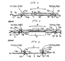
- FIG. 1 through FIG. 5 show a disk drive of an embodiment of the present invention, and a first supporting member through a fourth supporting member (14 through 17) are integrally molded on the chassis 3, four torsion coil springs 18 are engaged with the ends of each of the guide shafts 7A and 7B and the front ends of the four height adjusting screws 10 are pressed to the lower surface of both ends of each of the guide shafts 7A and 7B and a feeding motor 12 is linked and connected to an optical pick-up 6 via a driving mechanism 19 consisting of rack 19a, pinion 19b and gear 19c.
- the construction other than the above is similar to that described in FIG. 10 through FIG. 13, and the same symbols are given to the same parts to omit description thereof.
- the first supporting member 14 is provided with a vertical filler 14a erecting from the chassis 3 and a pair of horizontal fillers, 14b and 14c, extending toward both sides from the front end of the vertical filler 14a, a guide shaft engaging part 14A is formed by the vertical filler 14a and the horizontal filler 14b for allowing one end of one of the guide shafts 7A to be engaged, a spring engaging part 14B is formed by the vertical filler 14a and the horizontal filler 14c for allowing the torsion coil spring 18 to be engaged, and a concave groove 21 is formed on the lower edge of the horizontal filler 14c.
- the second supporting member 15 is provided with a vertical filler 15a erecting from the chassis 3 and a pair of horizontal fillers, 15b and 15c, extending toward both sides from the front end of the vertical filler 15a, a guide shaft engaging part 15A is formed by the vertical filler 15a and the horizontal filler 15b for allowing the other end of one of the guide shafts 7A, an engaging part 15B is formed by the vertical filler 15a and the horizontal filler 15c for allowing the torsion coil spring 18 to be engaged, and a concave groove 21 is formed on the lower edge of the horizontal filler 15C.
- the third supporting member 16 is provided with a vertical filler 16a erecting from the chassis 3 and a horizontal filler 16b extending laterally from the front end of the vertical filler 16a, a guide shaft engaging part 16A is formed for allowing one end of the other guide shaft 7B to be engaged by a rectangular engaging aperture 22 penetrated and installed on the vertical filler 16a, a spring engaging part 16B is formed for allowing the torsion coil spring 18 to be engaged by the vertical filler 16a and the horizontal filler 16b, and a concave groove 21 is formed on the lower edge of the horizontal filler 16b.
- the fourth supporting member 17 is provided with a pair of vertical fillers, 17a and 17b, erecting from the chassis 3, a guide shaft engaging part 17A is formed for allowing the other end of the other guide shaft 7B to be engaged by a concave part 23 recessed on the upper edge of the vertical filler 17a, a spring engaging part 17B is formed for allowing the torsion coil spring 18 to be engaged by the vertical filler 17b and horizontal filler 17c extending laterally from the front end of the vertical filler 17b, and a concave groove 21 is formed on the lower edge of the horizontal filler 17c.
- 24 denotes a guide shaft stopper cut out from the chassis 3
- 25 denotes an engaging part for the torsion coil spring formed on the chassis 3.
- the four supporting members (14 through 17) for supporting both ends of the guide shaft, 7A and 7B, are integrally molded on the chassis 3, it is possible to reduce the number of parts, depending on the number of the supporting members (14 through 17), for production at a lower cost than a conventional case where these supporting members (14 through 17) are outsert-molded.
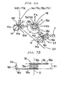
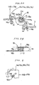
- the torsion coil spring 18 is provided with a coil part 18a, a pair of spring legs 18b extending from both ends of the coil part 18a in an approximately reverse-V shape in a mutually opposite way at a certain facing angle ⁇ , a pair of contacting parts, 18c and 18d, folded in an approximately V shape in a mutually opposite way along a virtual line S1 intersecting the axial center O of the coil part 18a at an approximately right angle from the front end of each of the spring legs 18b and running almost in parallel (refer to the virtual lines S2 and S3), an approximately V-shaped stopper part 18e folded outwardly in an approximately V-shape along the virtual line S1 intersecting the axial center O of the coil part 18a at an approximately right angle from the front end of the contacting part 18c and an approximately L-shaped stopper part 18f folded in an approximately L-shape along the virtual line S4 almost in parallel with the axial center O of the coil part 18a from the front end
- each torsion coil spring 18 is fitted outside the ends of each of the guide shafts 7A and 7B and a pair of contacting parts, 18c and 18d, extending from the coil part 18a are respectively brought into contact with engaging part 25 of the chassis 3 and the lower edge of the concave groove 21 of each of the supporting members, 14 through 17, at a facing angle ⁇ of approximately 45°.
- an approximately V-shaped stopper part 18e and an approximately L-shaped stopper part 18f extending from the front end of the contacting parts, 18c and 18d can prevent each of the contacting parts, 18c and 18d, from being accidentally dropped off from the engagingpart 25 or the concave groove 21 and both of the stopper parts, 18e and 18f, are folded in a different direction, it is possible to easily confirm the direction of the torsion coil spring 18 only by visually inspecting the folded direction.
- the approximately L-shaped stopper part 18f is caught, thereby allowing the coil part 18a to be fitted normally into the ends of each of the guide shafts 7Aand 7Bor the approximately V-shaped stopper part 18e is caught, thereby preventing a wrong fitting that the coil part 18a is fitted reversely into the ends of each of the guide shafts 7A and 7B so that the torsion coil spring 18 can be assembled efficiently.
Landscapes
- Moving Of Heads (AREA)
- Moving Of The Head For Recording And Reproducing By Optical Means (AREA)
- Optical Head (AREA)
- Holding Or Fastening Of Disk On Rotational Shaft (AREA)
Abstract
Description
Claims (5)
- A disk drive comprising:a turntable-equipped spindle motor that is provided at a front part of a metal plate-made chassis;an optical pick-up that is arranged in a central aperture of the chassis;four integrally supporting members that are formed on the chassis opposite the ends of the both right and left pairs of guide shafts movably supporting the optical pick-up, and are engaged with both ends of each guide shaft;torsion coil springs that are engaged between the end of each guide shaft and the chassis;a height adjusting screw fixed together with the thread groove of the chassis against each torsion coil spring;a feeding motor mounted on the chassis;a guide shaft engaging part for allowing the end of each guide shaft to be engaged;a spring engaging part for allowing each torsion coil spring to be engaged;a vertical filler that is erected from the chassis;a horizontal filler that is extended laterally from the front end of the vertical filler;a concave groove that is formed at the lower edge of each of the horizontal fillers;an inclined guide edge;a coil part;a pair of spring legs extending from both ends of the coil part in an approximately reverse-V shape in a mutually opposite way at a certain facing angle;a pair of contacting parts folded in an approximately V shape in amutuallyopposite way along the direction intersecting the axial center of the coil part at an approximately right angle from the front end of each of the spring legs and running almost in parallel,an approximately V-shaped stopper part folded outwardly in an approximately V-shape along the direction intersecting the axial center of the coil part at an approximately right angle from the front end of one of the contacting parts; andan approximately L-shaped stopper part folded in an approximately L-shape along the direction almost in parallel with the axial center of the coil part from the front end of the other contacting part, wherein:the front end of the height adjusting screw is pressed to the end of each guide shaft, by which the optical pick-up is adjusted for gradient angle toward the radial direction and the tangent direction via each guide shaft;a disk is rotated via the turntable by the spindle motor;the optical pick-up is moved via a driving mechanism by the feeding motor along the both guide shafts;the laser beam is emitted to the disk from the optical pick-up to read the information recorded on the disk;a part left after cutting during press-molding the chassis is pulled up and folded appropriately, thereby forming the four integrally supporting members on the chassis;each of the supporting members is provided with the guide shaft engaging part and the spring engaging part;each of the engaging parts is provided with the vertical filler and the horizontal filler;a corner extending from the upper edge of each of the horizontal fillers to the lower edge is cut, for which the inclined guide edge is formed;the torsion coil spring is provided with the coil part, the pair of spring legs, the pair of contacting parts, the approximately V-shaped stopper part and the approximately L-shaped stopper part;the coil part is fitted outside the end of each guide shaft;one of the contacting parts is engaged with an engaging part of the chassis and brought into contact with the lower edge of the engaging part at a facing angle of approximately 45°; andthe other contacting part is moved along the inclined guide edge from the upper edge of each horizontal filler to the lower edge, fitted into the concave groove, and brought into contact with the lower edge of the concave groove at a facing angle of approximately 45°.
- A disk drive comprising:a turntable-equipped spindle motor that is provided at a front part of a metal plate-made chassis;an optical pick-up that is arranged in a central aperture of the chassis;four supporting members that are engaged with ends of both right and left pairs of guide shafts movably supporting the optical pick-up;a height adjusting screw;a thread groove;a torsion coil spring; anda feeding motor that is mounted on the chassis, wherein:the front end of the height adjusting screw fixed together with the thread groove of the chassis against the torsion coil spring engaged with the end of each guide shaft is pressed to the end of each guide shaft, by which the optical pick-up is adjusted for gradient angle toward the radial direction and the tangent direction via each guide shaft;a disk is rotated via the turntable by the spindle motor;the optical pick-up is moved via the driving mechanism by the feeding motor along the both guide shafts;the laserbeamis emitted to the disk from the optical pick-up to read the information recorded on the disk, the disk drive; andthe four supporting members are integrally formed on the chassis by pulling up and folding appropriately a part left after cutting during press-molding the chassis.
- A disk drive according to Claim 2, further comprising:a coil part;a pair of spring legs extending from both ends of the coil part in an approximately reverse-V shape in a mutually opposite way at a certain facing angle; anda pair of contacting parts folded in an approximately V shape in a mutually opposite way along the direction intersecting the axial center of the coil part at an approximately right angle from the front end of each of the spring legs and running almost in parallel; wherein,the torsion coil spring is provided with the coil part, the pair of spring legs and the pair of contacting parts;the coil part is fitted outside the end of each guide shaft;one of the contacting parts is engaged with an engaging part of the chassis and brought into contact with the lower edge of the engaging part at a facing angle of approximately 45°; andthe other contacting part is fitted into a concave groove of each supporting member and brought into contact with the lower edge of the concave groove at a facing angle of approximately 45°.
- A disk drive according to Claim 3, further comprising:an approximately V-shaped stopper part folded outwardly in an approximately V-shape along the direction intersecting the axial center of the coil part at an approximately right angle from the front end of one of the contacting parts; andan approximately L-shaped stopper part folded in an approximately L-shape along the direction almost in parallel with the axial center of the coil part from the front end of the other contacting part.
- A disk drive according to Claim 3, further comprising:a guide shaft engaging part for allowing the end of each guide shaft to be engaged;a spring engaging part for allowing each torsion coil spring to be engaged;a vertical filler that is erected from the chassis;a horizontal filler that is extended laterally from the front end of the vertical filler; andan inclined guide edge, whereineach of the supporting members is provided with the guide shaft engaging part and the spring engaging part;each of the engaging parts is provided with the vertical filler and the horizontal filler;a corner extending from the upper edge of each horizontal filler to the lower edge is cut, by which the inclined guide edge is formed; andthe other contacting part of each torsion coil spring is moved along the inclined guide edge from the upper edge of each horizontal filler to the lower edge and fitted into the concave groove.
Applications Claiming Priority (2)
| Application Number | Priority Date | Filing Date | Title |
|---|---|---|---|
| JP2004152251A JP4124161B2 (en) | 2004-05-21 | 2004-05-21 | Disk unit |
| JP2004152251 | 2004-05-21 |
Publications (3)
| Publication Number | Publication Date |
|---|---|
| EP1600959A2 true EP1600959A2 (en) | 2005-11-30 |
| EP1600959A3 EP1600959A3 (en) | 2007-01-10 |
| EP1600959B1 EP1600959B1 (en) | 2008-02-27 |
Family
ID=34936759
Family Applications (1)
| Application Number | Title | Priority Date | Filing Date |
|---|---|---|---|
| EP05010977A Expired - Lifetime EP1600959B1 (en) | 2004-05-21 | 2005-05-20 | Disk drive |
Country Status (5)
| Country | Link |
|---|---|
| US (1) | US7472406B2 (en) |
| EP (1) | EP1600959B1 (en) |
| JP (1) | JP4124161B2 (en) |
| CN (1) | CN100458935C (en) |
| DE (1) | DE602005004951T2 (en) |
Cited By (1)
| Publication number | Priority date | Publication date | Assignee | Title |
|---|---|---|---|---|
| EP2355100A4 (en) * | 2009-01-07 | 2011-08-10 | Panasonic Corp | SHAFT SUPPORT STRUCTURE AND OPTICAL DISC DEVICE COMPRISING SAME |
Families Citing this family (13)
| Publication number | Priority date | Publication date | Assignee | Title |
|---|---|---|---|---|
| JP3889421B2 (en) * | 2004-11-18 | 2007-03-07 | 東芝サムスン ストレージ・テクノロジー株式会社 | Shaft support mechanism of optical disc apparatus and tilt adjustment mechanism of optical disc apparatus |
| JP2008004166A (en) * | 2006-06-22 | 2008-01-10 | Hitachi-Lg Data Storage Inc | Optical disk device |
| JP2009271969A (en) * | 2008-05-01 | 2009-11-19 | Funai Electric Co Ltd | Optical pickup and optical disc apparatus |
| WO2010070923A1 (en) * | 2008-12-18 | 2010-06-24 | パナソニック株式会社 | Disk device |
| KR101196628B1 (en) | 2009-12-21 | 2012-11-02 | 엘지이노텍 주식회사 | Structure of spindle motor |
| JP5573148B2 (en) * | 2009-12-22 | 2014-08-20 | 船井電機株式会社 | Optical disk device |
| KR101245394B1 (en) * | 2010-04-05 | 2013-03-19 | 엘지이노텍 주식회사 | Integrated disk driving module |
| KR101225242B1 (en) * | 2010-03-29 | 2013-01-22 | 엘지이노텍 주식회사 | Integrated disk driving module |
| US8448201B2 (en) * | 2010-03-29 | 2013-05-21 | Lg Innotek Co., Ltd. | Integrated disk driving module |
| KR101245473B1 (en) | 2010-03-29 | 2013-03-25 | 엘지이노텍 주식회사 | Integrated disk driving module |
| JP2013004146A (en) * | 2011-06-16 | 2013-01-07 | Funai Electric Co Ltd | Optical disk device |
| KR102218467B1 (en) * | 2015-02-25 | 2021-02-23 | 주식회사 히타치엘지 데이터 스토리지 코리아 | Optical disc drive |
| CN111546073A (en) * | 2020-05-19 | 2020-08-18 | 绍兴市上虞区舜昌金属制品有限公司 | Pipe fitting end face machining production line |
Family Cites Families (9)
| Publication number | Priority date | Publication date | Assignee | Title |
|---|---|---|---|---|
| KR0183889B1 (en) * | 1996-06-25 | 1999-04-15 | 김광호 | Tilt-adjustable disc player |
| JP2000057715A (en) * | 1998-08-05 | 2000-02-25 | Pioneer Electron Corp | Disc player |
| JP3364922B2 (en) * | 1999-02-22 | 2003-01-08 | 船井電機株式会社 | Pickup device |
| TW440048U (en) * | 1999-07-01 | 2001-06-07 | Ind Tech Res Inst | Mechanism for adjusting the guiding rod of the pickup head of a CD drive |
| JP3514673B2 (en) | 1999-09-07 | 2004-03-31 | アルプス電気株式会社 | Optical disk drive |
| JP2001101671A (en) * | 1999-09-28 | 2001-04-13 | Alps Electric Co Ltd | Optical disk drive |
| JP2002100131A (en) | 2000-09-26 | 2002-04-05 | Sharp Corp | Disk recording and playback device |
| JP2002222571A (en) | 2001-01-25 | 2002-08-09 | Mitsumi Electric Co Ltd | Height adjustment mechanism for the height of the guide shaft for optical pickup |
| DE10329778A1 (en) * | 2003-07-01 | 2005-01-27 | Deutsche Thomson-Brandt Gmbh | A recording or reproducing apparatus with a recording or reading device |
-
2004
- 2004-05-21 JP JP2004152251A patent/JP4124161B2/en not_active Expired - Fee Related
-
2005
- 2005-05-20 EP EP05010977A patent/EP1600959B1/en not_active Expired - Lifetime
- 2005-05-20 CN CNB2005100711377A patent/CN100458935C/en not_active Expired - Fee Related
- 2005-05-20 DE DE602005004951T patent/DE602005004951T2/en not_active Expired - Lifetime
- 2005-05-20 US US11/133,434 patent/US7472406B2/en not_active Expired - Fee Related
Cited By (4)
| Publication number | Priority date | Publication date | Assignee | Title |
|---|---|---|---|---|
| EP2355100A4 (en) * | 2009-01-07 | 2011-08-10 | Panasonic Corp | SHAFT SUPPORT STRUCTURE AND OPTICAL DISC DEVICE COMPRISING SAME |
| CN102203859A (en) * | 2009-01-07 | 2011-09-28 | 松下电器产业株式会社 | Shaft support structure and optical disk device comprising same |
| US8316388B2 (en) | 2009-01-07 | 2012-11-20 | Panasonic Corporation | Shaft supporting structure with coil spring for pressing shaft onto bearing, and optical disc apparatus including the same |
| CN102203859B (en) * | 2009-01-07 | 2015-07-08 | 松下电器产业株式会社 | Shaft support structure and optical disk device comprising same |
Also Published As
| Publication number | Publication date |
|---|---|
| US20050262525A1 (en) | 2005-11-24 |
| DE602005004951T2 (en) | 2009-02-26 |
| EP1600959B1 (en) | 2008-02-27 |
| US7472406B2 (en) | 2008-12-30 |
| DE602005004951D1 (en) | 2008-04-10 |
| EP1600959A3 (en) | 2007-01-10 |
| JP2005332531A (en) | 2005-12-02 |
| CN1700314A (en) | 2005-11-23 |
| CN100458935C (en) | 2009-02-04 |
| JP4124161B2 (en) | 2008-07-23 |
Similar Documents
| Publication | Publication Date | Title |
|---|---|---|
| EP1600959B1 (en) | Disk drive | |
| US6160780A (en) | Disc clamper and disc drive provided with the disc clamper | |
| JP2001307340A (en) | Disk drive device | |
| US6449238B2 (en) | Skew adjustment mechanism for an optical pick-up used in an optical disc drive | |
| US6351444B1 (en) | Pickup device with tilt adjusting mechanism | |
| US9786315B1 (en) | Disc device | |
| US6356525B1 (en) | Skew adjusting apparatus for an optical disc player | |
| US6802071B2 (en) | Optical pickup supporting device having simple and compact structure and capable of accurately supporting an optical pickup | |
| JP2001307438A (en) | Leaf spring mechanism and disk drive device | |
| CN1305045C (en) | Optical disk device and carriage feed mechanism therefor | |
| JP2517896B2 (en) | Head feeder | |
| EP1553600B1 (en) | Disk player | |
| JPH11306548A (en) | Disc playback device | |
| JP2903672B2 (en) | Optical pickup traverse feeder | |
| DE602004011236T2 (en) | DRIVE FOR A DISC OPTICAL CARRIER | |
| JP4453658B2 (en) | Optical disk unit | |
| JP2001307405A (en) | Disk drive device | |
| JP4226560B2 (en) | Disc player | |
| KR200324828Y1 (en) | A device for supporting a screw of disk player | |
| US8370866B2 (en) | Optical pickup supporting device with position adjustment mechanism and optical disc apparatus including the same | |
| JP3968784B2 (en) | Disc player | |
| JP5573148B2 (en) | Optical disk device | |
| US20060117334A1 (en) | Disk drive provided with optical pickup unit | |
| JPH01184768A (en) | Head assembly | |
| JP2005100603A (en) | Optical disk drive |
Legal Events
| Date | Code | Title | Description |
|---|---|---|---|
| PUAI | Public reference made under article 153(3) epc to a published international application that has entered the european phase |
Free format text: ORIGINAL CODE: 0009012 |
|
| AK | Designated contracting states |
Kind code of ref document: A2 Designated state(s): AT BE BG CH CY CZ DE DK EE ES FI FR GB GR HU IE IS IT LI LT LU MC NL PL PT RO SE SI SK TR |
|
| AX | Request for extension of the european patent |
Extension state: AL BA HR LV MK YU |
|
| PUAL | Search report despatched |
Free format text: ORIGINAL CODE: 0009013 |
|
| AK | Designated contracting states |
Kind code of ref document: A3 Designated state(s): AT BE BG CH CY CZ DE DK EE ES FI FR GB GR HU IE IS IT LI LT LU MC NL PL PT RO SE SI SK TR |
|
| AX | Request for extension of the european patent |
Extension state: AL BA HR LV MK YU |
|
| 17P | Request for examination filed |
Effective date: 20070302 |
|
| 17Q | First examination report despatched |
Effective date: 20070411 |
|
| GRAP | Despatch of communication of intention to grant a patent |
Free format text: ORIGINAL CODE: EPIDOSNIGR1 |
|
| AKX | Designation fees paid |
Designated state(s): DE FR GB |
|
| GRAS | Grant fee paid |
Free format text: ORIGINAL CODE: EPIDOSNIGR3 |
|
| GRAA | (expected) grant |
Free format text: ORIGINAL CODE: 0009210 |
|
| AK | Designated contracting states |
Kind code of ref document: B1 Designated state(s): DE FR GB |
|
| REG | Reference to a national code |
Ref country code: GB Ref legal event code: FG4D |
|
| REF | Corresponds to: |
Ref document number: 602005004951 Country of ref document: DE Date of ref document: 20080410 Kind code of ref document: P |
|
| ET | Fr: translation filed | ||
| PLBE | No opposition filed within time limit |
Free format text: ORIGINAL CODE: 0009261 |
|
| STAA | Information on the status of an ep patent application or granted ep patent |
Free format text: STATUS: NO OPPOSITION FILED WITHIN TIME LIMIT |
|
| 26N | No opposition filed |
Effective date: 20081128 |
|
| REG | Reference to a national code |
Ref country code: FR Ref legal event code: PLFP Year of fee payment: 12 |
|
| PGFP | Annual fee paid to national office [announced via postgrant information from national office to epo] |
Ref country code: GB Payment date: 20160518 Year of fee payment: 12 |
|
| PGFP | Annual fee paid to national office [announced via postgrant information from national office to epo] |
Ref country code: FR Payment date: 20160412 Year of fee payment: 12 |
|
| REG | Reference to a national code |
Ref country code: DE Ref legal event code: R084 Ref document number: 602005004951 Country of ref document: DE |
|
| GBPC | Gb: european patent ceased through non-payment of renewal fee |
Effective date: 20170520 |
|
| REG | Reference to a national code |
Ref country code: FR Ref legal event code: ST Effective date: 20180131 |
|
| PG25 | Lapsed in a contracting state [announced via postgrant information from national office to epo] |
Ref country code: GB Free format text: LAPSE BECAUSE OF NON-PAYMENT OF DUE FEES Effective date: 20170520 |
|
| PG25 | Lapsed in a contracting state [announced via postgrant information from national office to epo] |
Ref country code: FR Free format text: LAPSE BECAUSE OF NON-PAYMENT OF DUE FEES Effective date: 20170531 |
|
| PGFP | Annual fee paid to national office [announced via postgrant information from national office to epo] |
Ref country code: DE Payment date: 20200506 Year of fee payment: 16 |
|
| REG | Reference to a national code |
Ref country code: DE Ref legal event code: R119 Ref document number: 602005004951 Country of ref document: DE |
|
| PG25 | Lapsed in a contracting state [announced via postgrant information from national office to epo] |
Ref country code: DE Free format text: LAPSE BECAUSE OF NON-PAYMENT OF DUE FEES Effective date: 20211201 |