EP1600890A2 - Distortion correction of fish-eye image - Google Patents
Distortion correction of fish-eye image Download PDFInfo
- Publication number
- EP1600890A2 EP1600890A2 EP05250849A EP05250849A EP1600890A2 EP 1600890 A2 EP1600890 A2 EP 1600890A2 EP 05250849 A EP05250849 A EP 05250849A EP 05250849 A EP05250849 A EP 05250849A EP 1600890 A2 EP1600890 A2 EP 1600890A2
- Authority
- EP
- European Patent Office
- Prior art keywords
- fish
- image
- drawing area
- eye image
- real
- Prior art date
- Legal status (The legal status is an assumption and is not a legal conclusion. Google has not performed a legal analysis and makes no representation as to the accuracy of the status listed.)
- Withdrawn
Links
Images




Classifications
-
- G—PHYSICS
- G06—COMPUTING OR CALCULATING; COUNTING
- G06T—IMAGE DATA PROCESSING OR GENERATION, IN GENERAL
- G06T5/00—Image enhancement or restoration
- G06T5/80—Geometric correction
-
- G—PHYSICS
- G06—COMPUTING OR CALCULATING; COUNTING
- G06T—IMAGE DATA PROCESSING OR GENERATION, IN GENERAL
- G06T3/00—Geometric image transformations in the plane of the image
- G06T3/04—Context-preserving transformations, e.g. by using an importance map
- G06T3/047—Fisheye or wide-angle transformations
-
- H—ELECTRICITY
- H04—ELECTRIC COMMUNICATION TECHNIQUE
- H04N—PICTORIAL COMMUNICATION, e.g. TELEVISION
- H04N23/00—Cameras or camera modules comprising electronic image sensors; Control thereof
- H04N23/60—Control of cameras or camera modules
- H04N23/698—Control of cameras or camera modules for achieving an enlarged field of view, e.g. panoramic image capture
-
- H—ELECTRICITY
- H04—ELECTRIC COMMUNICATION TECHNIQUE
- H04N—PICTORIAL COMMUNICATION, e.g. TELEVISION
- H04N5/00—Details of television systems
- H04N5/222—Studio circuitry; Studio devices; Studio equipment
- H04N5/262—Studio circuits, e.g. for mixing, switching-over, change of character of image, other special effects ; Cameras specially adapted for the electronic generation of special effects
- H04N5/2628—Alteration of picture size, shape, position or orientation, e.g. zooming, rotation, rolling, perspective, translation
Definitions
- the present invention relates to an image providing method and device which nonlinearly develops on a display plane an image in any sight-line direction in a fish-eye image (omnidirectional image), and more particularly, to an interactive type image providing method and device which can provide in real-time an moving image in a direction intended by an observer.
- a method for collecting a wide-angle image using a monitoring camera with a fish-eye lens instead of a monitoring camera with a usual lens to obtain a wider monitorable area In this case, a monitoring camera with a fish-eye lens provides an fish-eye image more distorted than an image provided by a monitoring camera with a usual lens.
- a non-linear transformation processing is thus known that displays on a plane a distortion-removed image in any sight-line direction from the fish-eye image. Such a non-linear transformation processing is referred to a normalization processing (dewarp).
- dewarping logics are formulated into transformation equations that are generally similar.
- the dewarping methods have thus been implemented as a device with a programming language using any transformation equation, or implemented after fixing areas to be drawn at a plurality of places and creating previously a transformation rule in a table-lookup form based on a equation.
- a non-linear transformation processing uses a mapping on a sphere as a basis to sequentially calculate display pixels, and the dewarping is only performed in visual fields from a plurality of predetermined limited places, thereby providing poor interactivity.
- An image providing device comprises: a fish-eye image input device inputting fish-eye image; a fish-eye image storage device storing said input fish-eye image; a visual-field information input device inputting in real-time visual-field information including information on sight-line direction (theta, phi) and on field angle (gamma) in visual-field area of said fish-eye image; a drawing area calculation device for calculating in real-time, using said input visual-field information, each pixel of a drawing area in a plane which is orthogonal to said sight-line direction and has an extent determined by said field angle; and a dewarping processing device determining a pixel position in said fish-eye image which corresponds to each pixel position in said calculated drawing area to form in real-time a dewarped image from the fish-eye image with its distortion removed.
- FIGS 1 to 3 illustrate the basic concept of the dewarping processing according to the embodiment of the present invention.
- a fish-eye image can be regarded as an image (distorted all-direction image) derived from an object imaged on a hemispherical surface of a virtually established hemisphere S being developed on a plane (the circular bottom surface of the hemisphere S).
- a three-dimensional coordinate system is established with orthogonal directions X-axis and Y-axis from the origin O in a plane including the bottom circle and the direction Z-axis from the origin O extending toward the vertex of the hemisphere S.
- sight-line direction B is given by a zenithal angle (tilt) theta ( ⁇ ) of an angle from Z-axis and an azimuthal angle (pan) phi ( ⁇ ) of an angle from X-axis.
- This sight-line direction B is a visual-field center of a viewer.
- an additionally specified zoom magnification field angle gamma ( ⁇ ) specifies a portion to be drawn (viewed) as plane A (imaging plane of a virtual perspective camera) that is orthogonal to sight-line direction B and tangent to the hemispherical surface shown in Figure 1.
- Any position in plane A can be expressed in a two-dimensional coordinate system of Eu and Ev with the origin at intersection P with a line indicating sight-line direction B.
- This plane A is referred to a " drawing area.
- "Dewarping processing" corresponds to reconstruction of this drawing area from the original fish-eye image (distorted all-direction image developed on the circular bottom surface of hemisphere S).
- point Ps on plane A is expressed as an intersection between plane A and light ray C that is defined by zenithal angle theta s and azimuthal angle phi s.
- the brightness of point Ps can thus be determined by calculating the three-dimensional coordinates of point Ps with theta and phi of sight-line direction B to determine theta s and phi s of light ray C passing through point Ps, and by determining the pixel position of corresponding point Ps' in the fish-eye image based on a model equation of the fish-eye projection.
- Ku and Kv can be determined with a zoom magnification (field angle gamma) and the aspect ratio alpha of drawing area, as follows.
- Ku tan (gamma /2)
- Kv alpha * tan (gamma /2)
- the aspect ratio alpha depends on the window size of the drawing area. Given that the position in Eu-axis direction in plane A is u and the position in Ev-axis direction in plane A is v, three-dimensional coordinates (Px, Py, Pz) of point Ps can be determined as follows.
- the theta s and phi s determined can provide polar coordinates (L, phi s) of point Ps' in fish-eye image G corresponding to point Ps in plane A.
- the f is a focal length of the fish-eye lens.
- L 2 * r_px * theta s/pi
- X_pixel L * cos (phi s)
- Y_pixel L * sin (phi s)
- the focal position of the fish-eye lens and the resolution of the imaging element and the like may change the radius r_px of fish-eye image G and the pixel correspondence between the fish-eye image and dewarped image. Therefore, lens characteristics and CMOS (or CCD) characteristics are preferably considered in Ku and Kv calculation and dewarping processing.
- the management function device for general management including the input and output of images to and from the external and the interface with input device is separated from the computing module function for dewarping distortion.
- the dewarping-computing module preferably uses three parallel-processable computing modules.
- Figure 4 shows a configuration of an interactive type image display system according to the first embodiment of the present invention.
- This system includes: image providing device 1 for transforming a fish-eye image to a dewarped image in a designated visual-field; fish-eye imaging device 2 for providing in real-time an all-direction image, particularly a moving image, to the image providing device 1; digital-image file storage unit 3 for accumulating a fish-eye image that is previously imaged by the fish-eye imaging device and the like in a form of a digital-image file such as MPEG 2 file and JPEG file group and the like; input device 4 for inputting, as an external control, information such as the user-desired sight-line direction (theta, phi) and zoom magnification (field angle gamma); and output device 5 such as a monitor for displaying the dewarped image dewarped by image providing device 1.
- image providing device 1 for transforming a fish-eye image to a dewarped image in a designated visual-field
- Image providing device 1 includes mainly input processing unit 11 for performing an input processing (such as A/D conversion and various decoding processings) of the fish-eye image; transformation device 12 which is the core part of device 1; and D/A conversion unit 13 as an output part.
- Image providing device 1 also includes: input interface 14 for inputting information, such as a sight-line direction, from input device 4; fish-eye image storage unit 16 for storing original fish-eye image ; and dewarped-image storage unit 18 for storing dewarped image.
- Transformation device 12 further includes, management function unit 21 for overall management including the input and output of fish-eye image and dewarped image to and from the external and the interface with input device 4, and dewarping computing module 22 for dewarping distortion of fish-eye image.
- management function unit 21 for overall management including the input and output of fish-eye image and dewarped image to and from the external and the interface with input device 4, and dewarping computing module 22 for dewarping distortion of fish-eye image.
- the above-described configuration incorporates the image that is imaged by fish-eye imaging device 2 to the internal in real-time via input processing unit 11 and holds the image in fish-eye image storage unit 16 as an fish-eye image, under the management of management function unit 21.
- the image can also be input by performing an input processing of any file of digital-image files (such as MPEG 2 file and JPEG file group, for example) that are previously accumulated in digital-image file storage unit 3 and can also be held as a fish-eye image.
- the user can use input device 4 such as a joystick mouse to input the user-desired sight-line direction (theta phi), zoom magnification (field angle gamma) to the device of the embodiment.
- the input information is informed via interface 14 to management function unit 21.
- a simple keyboard mouse input is also possible as an input method for the input information.
- FIG. 5 is a flowchart of the processing flow of image providing device 1.
- Management function unit 21 includes a plurality of management modes. These management modes have (1) a mode for inputting real-time image from the fish-eye photographing system, (2) a mode for inputting accumulated image from the file, (3) a mode for inputting sight-line direction and zoom magnification for display and for controlling display.
- Management function unit 21 first operates to determine whether the fish-eye image reading is in the real-time type image input mode or accumulated image input mode (S1). If the reading is in the real-time type image input mode, the image is read in real-time via input processing unit 11 from fish-eye imaging device 2 (S2). If the reading is in the accumulated image input mode, the digital-image file is read via input processing unit 11 from digital-image file storage unit 3 (S3). After read, the fish-eye image is sequentially stored in fish-eye image storage unit 16.
- management function unit 21 performs the mode for inputting sight-line direction and zoom magnification for display and for controlling display to read from input device 4 the sight-line direction (theta, phi) and zoom magnification (gamma) as input information (S4).
- the user can use input device 4 such as a joystick mouse to change in real-time the desired sight-line direction and zoom magnification like the photographing operation of the camera.
- Management function unit 21 reads the input information in real-time.
- management function unit 21 After reading the sight-line direction (theta, phi) and zoom magnification (gamma), management function unit 21 computes the values of Ku and Kv specifying the extent of the drawing area based on the above-mentioned Equation 1 (S5).
- the Ku and Kv are preferably specified also in view of characteristic parameters such as previously stored lens characteristics and CMOS (or CCD) characteristics.
- Dewarping computing module 22 performs the dewarping processing for the drawing area (S7).
- Management function unit 21 uses the dewarped image to draw on output device 5 such as a monitor (S8). The above-described processings are performed each time the input information is read.
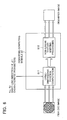
- FIG. 6 schematically shows the processing in the dewarping module.
- Dewarping computing module 22 performs the computation processing of the three-dimensional position of each pixel in the drawing area (S11) and three-dimensional non-linear texture mapping processing (S12) to dewarp the fish-eye image to create the dewarped image.
- the computation processing of the three-dimensional position of each pixel in the drawing area (S11) is conducted by, firstly inputting the extents Ku and Kv of the drawing areas calculated in management function unit 21, sight-line direction (theta, phi) provided by input device 4, and previously stored characteristic parameters of the lens and the imaging system and the like, and then operating the above-described Equation 2 to compute the three-dimensional position (Px, Py, Pz) of each pixel (Ps) in plane A indicating the drawing area with updated u and v.
- Non-linear texture mapping processing substitutes the computed results of the three-dimensional position (Px, Py, Pz) of each pixel into the above-described Equations 3 to 5 to calculate the pixel position (x_pixel, y_pixel) in the original fish-eye image G that corresponds to each pixel position in the dewarped image to be drawn in the drawing area, and maps the color information (such as RGB and YUV) at the pixel position in the original fish-eye image G to the corresponding pixel in the drawing area.
- the color information such as RGB and YUV
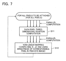
- the computation processing of the three-dimensional position (S11) and non-linear texture mapping processing (S12) can be performed independently for each pixel. Processings for a plurality of pixels can thus be computed in parallel. As shown in Figure 7, therefore, more hardware resources available such as CPU can provide more parallelism and less computation time in the computation processing (S11 and S12). This can draw a high-image-quality image in real-time and in an interactive manner.
- dewarping computing module 22 can be performed even more quickly using the graphics function such as a graphics dedicated processor (GPU). Specifically, significant processing can be performed on the graphics-board side by considering plane A indicating the drawing area in Figure 1 as the object of the texture mapping performed in three-dimension.
- graphics function such as a graphics dedicated processor (GPU).
- Figure 8 shows the dewarping processing using the graphics function.
- the processing falls into application software and graphics processing.
- the application software calculates the three-dimensional position of each point at four corners in the drawing area (P0, P1, P2, and P3 in Figure 2) (S21).
- the three-dimensional texture mapping and indent processing of the graphics processing on the graphics-board side performs the computation of each pixel position in the drawing area (S22) and non-linear texture mapping processing (S23).
- the interpolation processing from the three-dimensional positions of the four corners computes each pixel position in the drawing area.
- the calculation processing of the three-dimensional position of each point at four corners in the drawing area (S21) determines the direction vector V as shown in Figure 2 based on the sight-line direction (theta, phi), zoom magnification (field angle gamma), and characteristic parameters which are provided as input information.
- Axis vector Eu may be determined since its Z-component is zero and it is orthogonal with the direction vector V.
- plane A to be displayed has an extent within (-tan gamma /2, tan gamma /2) on Eu-axis. Because of the aspect ratio alpha being known from the drawing window size, the extent is within (-alpha * tan gamma /2, alpha * tan gamma /2) on Ev-axis.
- the three-dimensional coordinate values at four corners can thus be determined as follows using vector notation.
- Three-dimensional coordinates (Px, Py, Pz) of each point interpolated is then computed on the graphics-board side.
- the inverse function of the trigonometric function in the above-described Equation 3 used in non-linear texture mapping processing (S23) can be processed even more quickly by approximating the numerator and denominator with four-dimensional rational polynomials.
- Management function unit 21 in Figure 4 thus cuts out a portion of the original fish-eye image G for the processing.
- fish-eye image G divides into a plurality of blocks g and the decoding processing occurs for each block, as in Figure 9.
- Ku and Kv shown in Equation 1 and three-dimensional positions at four corners shown in Equation 7 are determined.
- the embodiment uses such information to calculate the coordinate values of eight points P1 to P8 around the area to be processed, and incorporates only blocks g (hatched blocks in Figure 9) containing these coordinate values as the blocks to be processed in input processing unit 11. This is possible in MPEG 2 and JPEG and the like, for example, by specifying the macro blocks to be processed. In CMOS camera, only cells to be processed may be captured.
- Step S6 in Figure 5 shows this processing. After the values of Ku and Kv are computed (S5), the cut-out blocks in the original fish-eye image are calculated (S6), and the limited number of images are read for the higher speed processing.
- Figure 10 shows the stereo image display system according to the fourth embodiment of the present invention.
- This system includes: two fish-eye-lens-equipped cameras 31 and 32 disposed in parallel; computer 33 containing two sets of image providing devices for the dewarping processing of the right and left fish-eye images from cameras 31 and 32; input device 34 for inputting the sight-line direction and zoom magnification to computer 33; output device 35 such as a monitor for alternately displaying the right and left dewarped images dewarped by computer 33; and liquid crystal shutter glasses 36 operating in synchronization with output device 35.
- Output device 35 may use a naked-eye stereovision display to omit liquid crystal shutter glasses 36.
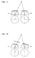
- virtual camera planes can be provided to the user which planes specify the same sight-line direction and zoom magnification for the two cameras corresponding to the right eye and left eye, respectively, and the stereoscopic images can be provided even by changing the virtual camera planes in an interactive manner at the same time. Specifically, images in the desired direction can be observed stereoscopically in an interactive manner.
- the sight-line changes from the front, a difference always occurs in the depth between one virtual camera plane and the other as shown in Figure 12.
- One plane can thus be corrected to be parallel with respect to the sight-line direction to make it possible to observe images stereoscopically.
- the distortion of the fish-eye lens can be dewarped quickly to help draw moving images quickly at any sight line and zoom.
- monitoring and appreciation can be done with interactive stereoscopic images.
- Such a system can draw moving images quickly and apply to broadcasting area available in real-time, image monitoring for in-vehicle use, and the like. Additionally, use of the system in stereovision can extend the appreciation of contents in the broadcasting area, for example.
- the system can be mounted on a vehicle for looking around extensively and stereoscopically in operating the vehicle in a narrow space such as parallel parking, which is very useful.
- the present invention is suited for application in real-time distributed contents such as broadcasting and mobile phone service, recording-and-reproducing type contents such as packaged media, and the like, particularly, in surveillance for vehicle operation support, and plant monitoring.
- the system in stereovision can extend the appreciation of contents in the broadcasting area, for example.
- the system can be mounted on a vehicle for looking around extensively and stereoscopically in operating the vehicle in a narrow space such as parallel parking, which is very useful.
Landscapes
- Engineering & Computer Science (AREA)
- Multimedia (AREA)
- Signal Processing (AREA)
- Physics & Mathematics (AREA)
- General Physics & Mathematics (AREA)
- Theoretical Computer Science (AREA)
- Image Processing (AREA)
- Closed-Circuit Television Systems (AREA)
- Testing, Inspecting, Measuring Of Stereoscopic Televisions And Televisions (AREA)
Abstract
Description
The following Equation 6 can compute axis vector Ev.
Claims (12)
- An image providing device comprising:a fish-eye image input device inputting fish-eye image;a fish-eye image storage device storing said input fish-eye image;a visual-field information input device inputting in real-time visual-field information including information on sight-line direction (theta, phi) and on field angle (gamma) in visual-field area of said fish-eye image;a drawing area calculation device for calculating in real-time, using said input visual-field information, each pixel of a drawing area in a plane which is orthogonal to said sight-line direction and has an extent determined by said field angle; anda dewarping processing device determining a pixel position in said fish-eye image which corresponds to each pixel position in said calculated drawing area to form in real-time a dewarped image from the fish-eye image with its distortion removed.
- An image-providing device according to claim 1, wherein said fish-eye image is a moving image.
- An image providing device according to any preceding claim, wherein on an assumption that said fish-eye image is an image derived from an object imaged on a hemispherical surface of a virtually established hemisphere being developed on a plane,
said drawing area calculating device calculates a plane tangent to said hemispherical surface as the drawing area,
said dewarping processing device comprises:a three-dimensional position computation device computing, for each pixel in said calculated drawing area, its three-dimensional position in a three-dimensional coordinate system with an origin at a center of a bottom circle of said hemisphere; anda non-linear mapping device calculating a zenithal angle theta s and an azimuthal angle phi s of an axis passing through said origin and a three-dimensional position of each pixel in said calculated drawing area, and using these zenithal angle and azimuthal angle as a basis to determine a pixel position in said fish-eye image. - An image providing device according to either of claims 1 or 2, wherein said drawing area calculating device calculates pixel positions at four corners of said drawing area,
said dewarping processing device calculates each pixel position in said drawing area from the pixel positions at the four corners in said drawing area by interpolation processing. - An image providing device according to any preceding claim, wherein said fish-eye images are divided into a plurality of blocks, each of which is separately accessible,
said image providing device further comprises to-be-read block calculating device calculating said blocks to be read from said calculated drawing area, and
said fish-eye image input device only inputs said calculated block to be read. - An image providing device according to any preceding claim, wherein said fish-eye image includes right and left two-system images for stereo display, said drawing area calculating device calculates a drawing area for each of said two-system fish-eye images based on said input visual-field information, and
said dewarping processing device forms, for each of said calculated two-system drawing areas, a dewarped image from each fish-eye image. - An image providing method comprising:inputting a fish-eye image and storing it in a storage device;inputting in real-time visual-field information including information on sight-line direction (theta, phi) and on field angle (gamma) in visual-field area of said fish-eye image;calculating in real-time, using said input visual-field information, each pixel of a drawing area in a plane which is orthogonal to said sight-line direction and has an extent determined by said field angle; anddetermining a pixel position in said fish-eye image which corresponds to each pixel position in said calculated drawing area to form in real-time a dewarped image from the fish-eye image with its distortion removed.
- An image providing method according to claim 7, wherein said fish-eye image is a moving image.
- An image providing method according to either of claims 7 or 8, wherein on an assumption that said fish-eye image is an image derived from an object imaged on a hemispherical surface of a virtually established hemisphere being developed on a plane,
said step of calculating a drawing area in real-time calculates a plane tangent to said hemispherical surface as the drawing area, and
said step of forming a dewarped image in real-time comprises:computing, for each pixel in said calculated drawing area, its three-dimensional position in a three-dimensional coordinate system with an origin at a center of a bottom circle of said hemisphere; andcalculating a zenithal angle theta s and an azimuthal angle phi s of an axis passing through said origin and a three-dimensional position of each pixel in said calculated drawing area, and using these zenithal angle and azimuthal angle as a basis to determine a pixel position in said fish-eye image. - An image providing method according to any of claims 7 to 9, wherein said step of calculating a drawing area in real-time calculates pixel positions at four corners of said drawing area, and
said step of forming a dewarped image in real-time calculates each pixel position in said drawing area from the pixel positions at the four corners in said drawing area by interpolation processing. - An image providing method according to any of claims 7 to 10, further comprising:dividing said fish-eye images into a plurality of blocks, each of which is separately accessible; andcalculating said blocks to be read from said calculated drawing area.
- An image providing method according to any of claims 7 to 11, wherein said fish-eye image includes right and left two-system images for stereo display,
said step of calculating a drawing area in real-time calculates a drawing area for each of said two-system fish-eye images based on said input visual-field information, and
said step of forming a dewarped image in real-time forms, for each of said calculated two-system drawing areas, a dewarped image from each fish-eye image.
Applications Claiming Priority (2)
| Application Number | Priority Date | Filing Date | Title |
|---|---|---|---|
| JP2004158855 | 2004-05-28 | ||
| JP2004158855A JP2005339313A (en) | 2004-05-28 | 2004-05-28 | Image presentation method and apparatus |
Publications (2)
| Publication Number | Publication Date |
|---|---|
| EP1600890A2 true EP1600890A2 (en) | 2005-11-30 |
| EP1600890A3 EP1600890A3 (en) | 2011-12-07 |
Family
ID=34940469
Family Applications (1)
| Application Number | Title | Priority Date | Filing Date |
|---|---|---|---|
| EP05250849A Withdrawn EP1600890A3 (en) | 2004-05-28 | 2005-02-15 | Distortion correction of fish-eye image |
Country Status (4)
| Country | Link |
|---|---|
| US (1) | US7570280B2 (en) |
| EP (1) | EP1600890A3 (en) |
| JP (1) | JP2005339313A (en) |
| CN (1) | CN100336076C (en) |
Cited By (6)
| Publication number | Priority date | Publication date | Assignee | Title |
|---|---|---|---|---|
| WO2010034299A1 (en) * | 2008-09-29 | 2010-04-01 | Mobotix Ag | Method for generating video data stream |
| US20120114262A1 (en) * | 2010-11-09 | 2012-05-10 | Chi-Chang Yu | Image correction method and related image correction system thereof |
| EP2444932A3 (en) * | 2010-08-31 | 2012-07-25 | Hitachi Information & Communication | Device, method and program for correcting an image |
| EP2172906A4 (en) * | 2008-06-06 | 2012-08-08 | Sony Corp | DEVICE, METHOD AND PROGRAM FOR GENERATING STEREOSCOPIC IMAGES |
| US20130258068A1 (en) * | 2012-03-30 | 2013-10-03 | General Electric Company | Methods and Systems for Predicting Cloud Movement |
| CN109792528A (en) * | 2016-09-19 | 2019-05-21 | 交互数字Vc控股公司 | The method and apparatus for indicating the point cloud of scene is reconstructed using light field data |
Families Citing this family (47)
| Publication number | Priority date | Publication date | Assignee | Title |
|---|---|---|---|---|
| JPWO2007108081A1 (en) * | 2006-03-20 | 2009-07-30 | 富士通株式会社 | Imaging apparatus, imaging method and program, imaging apparatus table creation apparatus and method, video processing apparatus and method |
| JP2007318596A (en) | 2006-05-29 | 2007-12-06 | Opt Kk | Compression method of image data by wide angle lens, expansion display method, compression apparatus, wide angle camera apparatus, and monitor system |
| JP2007318597A (en) * | 2006-05-29 | 2007-12-06 | Opt Kk | Compression method of image data by wide angle lens, compression apparatus, wide angle camera apparatus, and monitor system |
| US7774951B2 (en) * | 2006-10-04 | 2010-08-17 | Northwestern University | Sensing device with whisker elements |
| JP4931055B2 (en) * | 2006-11-22 | 2012-05-16 | ソニー株式会社 | Image processing apparatus and image processing method |
| JP2008197829A (en) * | 2007-02-09 | 2008-08-28 | Sony Corp | Image processing apparatus and method, program, and recording medium |
| JP2008227582A (en) * | 2007-03-08 | 2008-09-25 | Hoya Corp | Imaging apparatus |
| GB2449631B (en) * | 2007-05-21 | 2012-02-15 | Doo Technologies Fze | Method and system for processing of images |
| US8326077B2 (en) * | 2008-10-31 | 2012-12-04 | General Instrument Corporation | Method and apparatus for transforming a non-linear lens-distorted image |
| JP5353393B2 (en) * | 2009-04-07 | 2013-11-27 | 大日本印刷株式会社 | Image processing apparatus and image processing method |
| US8320634B2 (en) * | 2009-07-11 | 2012-11-27 | Richard Deutsch | System and method for monitoring protective garments |
| US20110134245A1 (en) * | 2009-12-07 | 2011-06-09 | Irvine Sensors Corporation | Compact intelligent surveillance system comprising intent recognition |
| WO2011121741A1 (en) * | 2010-03-30 | 2011-10-06 | 富士通株式会社 | Image generation device, image generation program, synthesis table generation device, and synthesis table generation program |
| JP5555101B2 (en) * | 2010-08-31 | 2014-07-23 | 株式会社日立情報通信エンジニアリング | Image correction apparatus, corrected image generation method, and corrected image generation program |
| US9105090B2 (en) | 2011-07-13 | 2015-08-11 | Analog Devices, Inc. | Wide-angle lens image correction |
| EP2554434B1 (en) * | 2011-08-05 | 2014-05-21 | Harman Becker Automotive Systems GmbH | Vehicle surround view system |
| JP5790345B2 (en) * | 2011-09-07 | 2015-10-07 | 株式会社リコー | Image processing apparatus, image processing method, program, and image processing system |
| JP5423845B2 (en) * | 2012-06-25 | 2014-02-19 | ソニー株式会社 | Stereoscopic image generation apparatus, stereoscopic image generation method, and program |
| JP2014165763A (en) * | 2013-02-26 | 2014-09-08 | Ricoh Co Ltd | Editing device, editing method, and editing program |
| US9183666B2 (en) | 2013-03-15 | 2015-11-10 | Google Inc. | System and method for overlaying two-dimensional map data on a three-dimensional scene |
| US9286712B2 (en) * | 2013-03-15 | 2016-03-15 | Google Inc. | System and method for approximating cartographic projections by linear transformation |
| US20160007014A1 (en) * | 2013-03-15 | 2016-01-07 | Matthew HENDERSHOT | Equidistant stereo lens shader |
| US8798451B1 (en) * | 2013-06-15 | 2014-08-05 | Gyeongil Kweon | Methods of obtaining panoramic images using rotationally symmetric wide-angle lenses and devices thereof |
| JP5666069B1 (en) * | 2013-06-24 | 2015-02-12 | 三菱電機株式会社 | Coordinate calculation apparatus and method, and image processing apparatus and method |
| US9658688B2 (en) * | 2013-10-15 | 2017-05-23 | Microsoft Technology Licensing, Llc | Automatic view adjustment |
| US9196022B2 (en) * | 2014-03-10 | 2015-11-24 | Omnivision Technologies, Inc. | Image transformation and multi-view output systems and methods |
| JP6398457B2 (en) * | 2014-08-14 | 2018-10-03 | 株式会社リコー | Imaging apparatus, imaging method, and program |
| CN105632349B (en) * | 2014-10-27 | 2018-04-10 | 深圳市康硕展电子有限公司 | L ED spherical display screen playing management method, device and system |
| JP2016163150A (en) * | 2015-02-27 | 2016-09-05 | 株式会社リコー | Communication terminal, interview system, communication method, and program |
| US10453173B2 (en) | 2015-07-24 | 2019-10-22 | Robert Bosch Gmbh | Panel transform |
| CN107016319B (en) * | 2016-01-27 | 2021-03-05 | 北京三星通信技术研究有限公司 | Feature point positioning method and device |
| KR20170124814A (en) * | 2016-05-03 | 2017-11-13 | 삼성전자주식회사 | Image display apparatus and operating method for the same |
| US9609197B1 (en) | 2016-08-19 | 2017-03-28 | Intelligent Security Systems Corporation | Systems and methods for dewarping images |
| US9547883B1 (en) | 2016-08-19 | 2017-01-17 | Intelligent Security Systems Corporation | Systems and methods for dewarping images |
| WO2018037789A1 (en) | 2016-08-22 | 2018-03-01 | ソニー株式会社 | Image processing device, image processing method, and program |
| KR102505951B1 (en) * | 2016-08-24 | 2023-03-03 | 한화테크윈 주식회사 | Apparatus and method for providing image, and computer program recorded on computer readable medium for excuting the method |
| US11049219B2 (en) * | 2017-06-06 | 2021-06-29 | Gopro, Inc. | Methods and apparatus for multi-encoder processing of high resolution content |
| JP6938237B2 (en) * | 2017-06-21 | 2021-09-22 | キヤノン株式会社 | Information processing equipment, information processing methods and programs |
| WO2019041035A1 (en) | 2017-08-30 | 2019-03-07 | Innovations Mindtrick Inc. | Viewer-adjusted stereoscopic image display |
| KR102377499B1 (en) * | 2018-02-08 | 2022-03-24 | 이노베이션스 마인드트릭 인크. | Viewer-adjustable stereoscopic image display |
| JP6610740B2 (en) * | 2018-09-06 | 2019-11-27 | 株式会社リコー | Imaging apparatus, imaging method, and program |
| US11109067B2 (en) | 2019-06-26 | 2021-08-31 | Gopro, Inc. | Methods and apparatus for maximizing codec bandwidth in video applications |
| US11228781B2 (en) | 2019-06-26 | 2022-01-18 | Gopro, Inc. | Methods and apparatus for maximizing codec bandwidth in video applications |
| US11481863B2 (en) | 2019-10-23 | 2022-10-25 | Gopro, Inc. | Methods and apparatus for hardware accelerated image processing for spherical projections |
| CN112565730B (en) * | 2020-12-03 | 2023-07-25 | 阿波罗智联(北京)科技有限公司 | Roadside sensing method, device, electronic equipment, storage medium and roadside equipment |
| CN114633692B (en) * | 2022-03-14 | 2023-10-03 | 深圳市艾为智能有限公司 | Application method of eccentric lens in CMS system |
| EP4568238B1 (en) * | 2023-12-07 | 2026-03-18 | Sick Ag | Surroundings monitoring device and method for operating a surroundings monitoring device |
Family Cites Families (10)
| Publication number | Priority date | Publication date | Assignee | Title |
|---|---|---|---|---|
| US5004328A (en) * | 1986-09-26 | 1991-04-02 | Canon Kabushiki Kaisha | Spherical lens and imaging device using the same |
| US5185667A (en) * | 1991-05-13 | 1993-02-09 | Telerobotics International, Inc. | Omniview motionless camera orientation system |
| US5796426A (en) * | 1994-05-27 | 1998-08-18 | Warp, Ltd. | Wide-angle image dewarping method and apparatus |
| DE69634221T2 (en) * | 1995-03-31 | 2006-05-18 | Canon K.K. | Method and device for processing visual information |
| US5691765A (en) * | 1995-07-27 | 1997-11-25 | Sensormatic Electronics Corporation | Image forming and processing device and method for use with no moving parts camera |
| JP3126955B2 (en) * | 1999-02-12 | 2001-01-22 | 株式会社アドバネット | Arithmetic unit for image conversion |
| JP2002098538A (en) * | 2000-09-27 | 2002-04-05 | Alpine Electronics Inc | Navigation system and method for displaying information of pseudo three dimensional map |
| CN1332564A (en) * | 2001-01-22 | 2002-01-23 | 耿刚 | Omnibearing imaging and transferring method and system |
| FR2827680B1 (en) * | 2001-07-20 | 2003-10-10 | Immervision Internat Pte Ltd | METHOD FOR CAPTURING A PANORAMIC IMAGE USING A RECTANGULAR IMAGE SENSOR |
| US6833843B2 (en) * | 2001-12-03 | 2004-12-21 | Tempest Microsystems | Panoramic imaging and display system with canonical magnifier |
-
2004
- 2004-05-28 JP JP2004158855A patent/JP2005339313A/en active Pending
-
2005
- 2005-02-07 CN CNB2005100082676A patent/CN100336076C/en not_active Expired - Fee Related
- 2005-02-10 US US11/053,947 patent/US7570280B2/en not_active Expired - Fee Related
- 2005-02-15 EP EP05250849A patent/EP1600890A3/en not_active Withdrawn
Cited By (11)
| Publication number | Priority date | Publication date | Assignee | Title |
|---|---|---|---|---|
| EP2172906A4 (en) * | 2008-06-06 | 2012-08-08 | Sony Corp | DEVICE, METHOD AND PROGRAM FOR GENERATING STEREOSCOPIC IMAGES |
| US9507165B2 (en) | 2008-06-06 | 2016-11-29 | Sony Corporation | Stereoscopic image generation apparatus, stereoscopic image generation method, and program |
| WO2010034299A1 (en) * | 2008-09-29 | 2010-04-01 | Mobotix Ag | Method for generating video data stream |
| US9098910B2 (en) | 2008-09-29 | 2015-08-04 | Mobotix Ag | Method for generating video data stream |
| EP2444932A3 (en) * | 2010-08-31 | 2012-07-25 | Hitachi Information & Communication | Device, method and program for correcting an image |
| US8630506B2 (en) | 2010-08-31 | 2014-01-14 | Hitachi Information & Communication Engineering, Ltd. | Image correcting device, method for creating corrected image, correction table creating device, method for creating correction table, program for creating correction table, and program for creating corrected image |
| US20120114262A1 (en) * | 2010-11-09 | 2012-05-10 | Chi-Chang Yu | Image correction method and related image correction system thereof |
| US9153014B2 (en) * | 2010-11-09 | 2015-10-06 | Avisonic Technology Corporation | Image correction method and related image correction system thereof |
| US20130258068A1 (en) * | 2012-03-30 | 2013-10-03 | General Electric Company | Methods and Systems for Predicting Cloud Movement |
| US9007460B2 (en) * | 2012-03-30 | 2015-04-14 | General Electric Company | Methods and systems for predicting cloud movement |
| CN109792528A (en) * | 2016-09-19 | 2019-05-21 | 交互数字Vc控股公司 | The method and apparatus for indicating the point cloud of scene is reconstructed using light field data |
Also Published As
| Publication number | Publication date |
|---|---|
| CN100336076C (en) | 2007-09-05 |
| CN1702693A (en) | 2005-11-30 |
| JP2005339313A (en) | 2005-12-08 |
| US7570280B2 (en) | 2009-08-04 |
| US20050265619A1 (en) | 2005-12-01 |
| EP1600890A3 (en) | 2011-12-07 |
Similar Documents
| Publication | Publication Date | Title |
|---|---|---|
| US7570280B2 (en) | Image providing method and device | |
| US9436973B2 (en) | Coordinate computation device and method, and an image processing device and method | |
| KR101912396B1 (en) | Apparatus and Method for Generating Image at any point-view based on virtual camera | |
| JP5739584B2 (en) | 3D image synthesizing apparatus and method for visualizing vehicle periphery | |
| EP3534336B1 (en) | Panoramic image generating method and apparatus | |
| CN108520232B (en) | Method and device for generating three-dimensional panoramic film | |
| CN106251403B (en) | A kind of methods, devices and systems of virtual three-dimensional Scene realization | |
| JP4642723B2 (en) | Image generating apparatus and image generating method | |
| JP4661829B2 (en) | Image data conversion device and camera device provided with the same | |
| KR101521008B1 (en) | Correction method of distortion image obtained by using fisheye lens and image display system implementing thereof | |
| US20100194902A1 (en) | Method for high dynamic range imaging | |
| EP3846464A1 (en) | Spherical image processing method and apparatus, and server | |
| JP6672315B2 (en) | Image generation device and image display control device | |
| CN106127681B (en) | A kind of image-pickup method, virtual reality image transmission method and display methods | |
| CN103839227A (en) | Fisheye image correction method and device | |
| US20130215298A1 (en) | Image processing method, image processing apparatus and image capturing apparatus | |
| CN111226264A (en) | Playback apparatus and method, and generation apparatus and method | |
| CN103020900A (en) | Method and device for image processing | |
| EP3691249A1 (en) | Image signal representing a scene | |
| EP3573018B1 (en) | Image generation device, and image display control device | |
| CN114513646B (en) | A method and device for generating panoramic video in a three-dimensional virtual scene | |
| JP3594225B2 (en) | Wide-field camera device | |
| CN114511447A (en) | Image processing method, device, equipment and computer storage medium | |
| TW201911239A (en) | Method and apparatus for generating three-dimensional panoramic video | |
| CN119052444A (en) | Immersive stereoscopic panoramic video real-time homography correction and projection method and device |
Legal Events
| Date | Code | Title | Description |
|---|---|---|---|
| PUAI | Public reference made under article 153(3) epc to a published international application that has entered the european phase |
Free format text: ORIGINAL CODE: 0009012 |
|
| 17P | Request for examination filed |
Effective date: 20050302 |
|
| AK | Designated contracting states |
Kind code of ref document: A2 Designated state(s): AT BE BG CH CY CZ DE DK EE ES FI FR GB GR HU IE IS IT LI LT LU MC NL PL PT RO SE SI SK TR |
|
| AX | Request for extension of the european patent |
Extension state: AL BA HR LV MK YU |
|
| PUAL | Search report despatched |
Free format text: ORIGINAL CODE: 0009013 |
|
| AK | Designated contracting states |
Kind code of ref document: A3 Designated state(s): AT BE BG CH CY CZ DE DK EE ES FI FR GB GR HU IE IS IT LI LT LU MC NL PL PT RO SE SI SK TR |
|
| AX | Request for extension of the european patent |
Extension state: AL BA HR LV MK YU |
|
| RIC1 | Information provided on ipc code assigned before grant |
Ipc: G06T 5/00 20060101ALN20111103BHEP Ipc: G06T 3/00 20060101AFI20111103BHEP |
|
| STAA | Information on the status of an ep patent application or granted ep patent |
Free format text: STATUS: THE APPLICATION HAS BEEN WITHDRAWN |
|
| 18W | Application withdrawn |
Effective date: 20120706 |
|
| AKX | Designation fees paid |
Designated state(s): DE FR GB |