EP1600827A2 - A wire module for developer unit - Google Patents
A wire module for developer unit Download PDFInfo
- Publication number
- EP1600827A2 EP1600827A2 EP05104457A EP05104457A EP1600827A2 EP 1600827 A2 EP1600827 A2 EP 1600827A2 EP 05104457 A EP05104457 A EP 05104457A EP 05104457 A EP05104457 A EP 05104457A EP 1600827 A2 EP1600827 A2 EP 1600827A2
- Authority
- EP
- European Patent Office
- Prior art keywords
- wire
- toner
- development zone
- donor
- drive system
- Prior art date
- Legal status (The legal status is an assumption and is not a legal conclusion. Google has not performed a legal analysis and makes no representation as to the accuracy of the status listed.)
- Withdrawn
Links
Images



Classifications
-
- G—PHYSICS
- G03—PHOTOGRAPHY; CINEMATOGRAPHY; ANALOGOUS TECHNIQUES USING WAVES OTHER THAN OPTICAL WAVES; ELECTROGRAPHY; HOLOGRAPHY
- G03G—ELECTROGRAPHY; ELECTROPHOTOGRAPHY; MAGNETOGRAPHY
- G03G15/00—Apparatus for electrographic processes using a charge pattern
- G03G15/06—Apparatus for electrographic processes using a charge pattern for developing
- G03G15/08—Apparatus for electrographic processes using a charge pattern for developing using a solid developer, e.g. powder developer
- G03G15/0803—Apparatus for electrographic processes using a charge pattern for developing using a solid developer, e.g. powder developer in a powder cloud
-
- G—PHYSICS
- G03—PHOTOGRAPHY; CINEMATOGRAPHY; ANALOGOUS TECHNIQUES USING WAVES OTHER THAN OPTICAL WAVES; ELECTROGRAPHY; HOLOGRAPHY
- G03G—ELECTROGRAPHY; ELECTROPHOTOGRAPHY; MAGNETOGRAPHY
- G03G2215/00—Apparatus for electrophotographic processes
- G03G2215/02—Arrangements for laying down a uniform charge
- G03G2215/026—Arrangements for laying down a uniform charge by coronas
- G03G2215/027—Arrangements for laying down a uniform charge by coronas using wires
-
- G—PHYSICS
- G03—PHOTOGRAPHY; CINEMATOGRAPHY; ANALOGOUS TECHNIQUES USING WAVES OTHER THAN OPTICAL WAVES; ELECTROGRAPHY; HOLOGRAPHY
- G03G—ELECTROGRAPHY; ELECTROPHOTOGRAPHY; MAGNETOGRAPHY
- G03G2215/00—Apparatus for electrophotographic processes
- G03G2215/06—Developing structures, details
- G03G2215/0634—Developing device
- G03G2215/0636—Specific type of dry developer device
- G03G2215/0643—Electrodes in developing area, e.g. wires, not belonging to the main donor part
Definitions
- This invention relates generally to an electrophotographic printing machine, and more particularly concerns wire module having translating wires driven by rotating spools for use in a scavengeless developer unit.
- the process of electrophotographic printing includes charging a photoconductive member to a substantially uniform potential so as to sensitize the surface thereof.
- the charged portion of the photoconductive surface is exposed to a light image of an original document being reproduced.
- the latent image is developed by bringing a developer material into contact therewith.
- Two component and single component developer materials are commonly used.
- a typical two component developer material has magnetic carrier granules with toner particles adhering triboelectrically thereto.
- a single component developer material typically comprises toner particles. Toner particles are attracted to the latent image forming a toner powder image on the photoconductive member.
- the toner powder image is subsequently transferred to a copy sheet.
- the toner powder image is heated to permanently fuse it to the copy sheet in image configuration.
- One type of single component development system is a scavengeless development system that uses a donor roll for transporting charged toner to a development zone.
- a plurality of electrode wires are closely spaced to the donor roll in the development zone.
- An AC voltage is applied to the wires forming a toner cloud in the development zone.
- the electrostatic fields generated by the latent image attract toner from the toner cloud to develop the latent image.
- a hybrid scavengeless development system employs a magnetic brush developer roller for transporting carrier having toner adhering triboelectrically thereto.
- the donor roll and magnetic brush roll are electrically biased relative to one another. Toner is attracted to the donor roll from the magnetic brush roll.
- the donor roll transports the charged toner to a development zone.
- the electrically biased electrode wires detach the toner from the donor roll forming a toner powder cloud in the development zone, and the latent image attracts the toner particles thereto. In this way, the latent image recorded on the photoconductive member is developed with the toner particles. It has been found that streaks are formed in the developed latent image when debris is trapped in, or when toner and/or toner constituents builds up on the electrode wires.
- the electrode wires have been positioned substantially perpendicular to the process direction, i.e. substantially parallel to the longitudinal axis of the donor roll.
- Various types of development systems have hereinbefore been used incorporating electrode wires as illustrated by the following disclosures, which may be relevant to certain aspects of the present invention:
- U.S. Patent No. 4,868,600 describes an apparatus wherein a magnetic roll transports two component developers to a transfer region where toner from the magnetic roll is transferred to a donor roll.
- the donor roll transports the toner to a region opposed from a surface on which a latent image is recorded.
- a pair of electrode wires are positioned in the space between the surface and the donor roll and are electrically biased to detach toner from the donor roll to form a toner cloud. Detach toner from the cloud develops the latent image.
- U.S. Patent No. 4,984,019 discloses a developer unit having a donor roll with electrode wires disposed adjacent thereto in a development zone.
- a magnetic roll transports developer material to the donor roll. Toner particles are attracted from the magnetic roll to the donor roll.
- the electrode wires are vibrated to remove contaminants therefrom.
- U.S. Patent No. 5,422,709 teaches an apparatus in which a donor roll advances toner to an electrostatic latent image recorded on a photoconductive member.
- a plurality of electrode wires are positioned in the space between the donor roll and the photoconductive member.
- the electrode wires extend in a transverse direction relative to the longitudinal axis of the donor roll.
- the electrode wires are electrically biased to detach the toner from the donor roll so as to form a toner cloud in the space between the electrode wires and photoconductive members. Detached toner from the toner cloud develops the latent image.
- Electrode wires contact a portion of the surface of the donor roll. As the donor roll rotates, friction between the electrode wires and donor roll causes trapped debris to move away from the toner powder cloud region so as to minimize contamination produced streaks on the developed image.
- Wire contamination is a first class of defect in which toner and/or toner constituents buildup on the wire side that is in contact with the donor roll.
- Wire history is a second class of defect in which toner and/or toner constituents buildup on the wire side away from the donor roll.
- Wire history involves highly charged (though sometimes low charged) and generally small toner or other particles being attracted to the wire and sticking to the wire as a result of either adhesive or electrostatic attractive forces. The result is that contaminants build up on the electrodes, as a response to the image area coverage history, causing visible streaks on prints. Constant cleaning of the wires is required in order to alleviate the above-defects, which cleaning is time-consuming and inefficient in that it requires machine downtime.
- the present invention obviates the problems noted above by providing an apparatus for developing in a development zone a latent image recorded on a surface, including a housing defining a chamber storing at least a supply of toner therein; a donor member disposed of at least partially in the chamber of said housing and spaced from the surface, said donor member being adapted to rotate about a longitudinal axis to transport toner to the development zone in a region opposed from the surface; and a wire assembly module mounted the development zone and extending in a direction transverse to the longitudinal axis, said wire assembly module including a wire and a drive system for translating portions of the wire in the development zone, and power supply for electrically biasing said wire to detach toner from said donor member so as to form a toner powder cloud in the development zone with detached toner from the toner cloud developing the latent image.
- the present invention relates to an electrophotographic printing machine for developing in a development zone a latent image recorded on a imageable surface, wherein the machine comprises an apparatus as defined in any of claims 1 to 10.
- said a wire assembly module further includes a stringing system for arranging said wire into plurality of elongated wires with adjacent wires being spaced from and substantially parallel to one another.
- said drive system includes means for supporting said plurality of wires at a preselected tension.
- said plurality of wires contacts said donor member.
- Figure 1 is a schematic elevational view of an illustrative electrophotographic printing machine
- the minor axis 118 is substantially perpendicular to the gravitational vector and arranged in a substantially horizontal direction.
- the printing machine architecture includes five image recording stations indicated generally by the reference numerals 16, 18, 20, 22, and 24, respectively.
- image recording station 16 includes a charging device and an exposure device.
- the charging device includes a corona generator 26 that charges the exterior surface of photoconductive belt 10 to a relatively high, substantially uniform potential. After the exterior surface of photoconductive belt 10 is charged, the charged portion thereof advances to the exposure device.
- the exposure device includes a raster output scanner (ROS) 28, which illuminates the charged portion of the exterior surface of photoconductive belt 10 to record a first electrostatic latent image thereon.
- ROS raster output scanner
- LED light emitting diode
- This first electrostatic latent image is developed by developer unit 30.
- Developer unit 30 deposits toner particles of a selected color on the first electrostatic latent image. After the highlight toner image has been developed on the exterior surface of photoconductive belt 10, photoconductive belt 10 continues to advance in the direction of arrow 14 to image recording station 18.
- Image recording station 20 includes a charging device and an exposure device.
- the charging device includes corona generator 38, which recharges the photoconductive surface to a relatively high, substantially uniform potential.
- the exposure device includes ROS 40 which illuminates the charged portion of the exterior surface of photoconductive belt 10 to selectively dissipate the charge thereon to record a third electrostatic latent image corresponding to the regions to be developed with yellow toner particles. This third electrostatic latent image is now advanced to the next successive developer unit 42.
- black toner particles are deposited on the exterior surface of photoconductive belt 10. These black toner particles form a black toner powder image which may be partially or totally in superimposed registration with the previously formed highlight color, yellow, magenta, and cyan toner powder images. In this way, a multi-color toner powder image is formed on the exterior surface of photoconductive belt 10. Thereafter, photoconductive belt 10 advances the multi-color toner powder image to a transfer station, indicated generally by the reference numeral 56.
- All xerographic subsystems are environmentally maintained inside the xero cavity. Air from and to the xero cavity is conditioned/filtered to predefined set points by using a special design environmental unit 510.
- a receiving medium i.e., paper
- a corona generating device 60 sprays ions onto the backside of the paper. This attracts the developed multi-color toner image from the exterior surface of photoconductive belt 10 to the sheet of paper.
- Stripping assist roller 66 contacts the interior surface of photoconductive belt 10 and provides a sufficiently sharp bend thereat so that the beam strength of the advancing paper is stripped from photoconductive belt 10.
- a vacuum transport moves the sheet of paper in the direction of arrow 62 to fusing station 64.
- Fusing station 64 includes a heated fuser roller 70 and a back-up roller 68.
- the back-up roller 68 is resiliently urged into engagement with the fuser roller 70 to form a nip through which the sheet of paper passes.
- the toner particles coalesce with one another and bond to the sheet in image configuration, forming a multi-color image thereon.
- the finished sheet is discharged to a finishing station where the sheets are compiled and formed into sets which may be bound to one another. These sets are then advanced to a catch tray for subsequent removal therefrom by the printing machine operator.
- multi-color developed image has been disclosed as being transferred to paper, it may be transferred to an intermediate member, such as a belt or drum, and then subsequently transferred and fused to the paper.
- an intermediate member such as a belt or drum
- toner powder images and toner particles have been disclosed herein, one skilled in the art will appreciate that a liquid developer material employing toner particles in a liquid carrier may also be used.
- the magnetic brush roll 170 comprises a rotatable tubular housing within which is located a stationary magnetic cylinder having a plurality of magnetic poles impressed around its surface.
- the carrier granules of the developer material are permeable, as the tubular housing of the magnetic brush roll 170 rotates, the granules (with toner particles adhering triboelectrically thereto) are attracted to the magnetic brush roll 170 and are conveyed to the donor roll loading nips.
- a trim bar 180 removes excess developer material from the magnetic brush roll 170 and ensures an even depth of coverage with developer material before arrival at the first donor roll loading nip 176. At each of the donor roll loading nips, toner particles are transferred from the magnetic brush roll 170 to the respective donor rolls 176, 178.
- the carrier granules and any toner particles that remain on the magnetic brush roll 170 are returned to the reservoir 164 as the magnetic brush roll 170 continues to rotate.
- the relative amounts of toner transferred from the magnetic brush roll 170 to the donor rolls 176, 178 can be adjusted, for example by: applying different bias voltages to the donor rolls 176, 178; adjusting the magnetic brush roll to donor roll spacing; adjusting the strength and shape of the magnetic field at the loading nips and/or adjusting the speeds of the donor rolls 176, 178.
- each of the development zones is shown as having the form i.e. electrode wires 186, 188 are disposed in the space between each donor rolls 176, 178 and photoconductive belt 10.
- Figure 2 shows, for each donor rolls 176, 178 a respective pair of electrode wires 186, 188 extending in a direction substantially parallel to the longitudinal axis of the donor rolls 176, 178.
- the electrode wires 186, 188 are made from thin (i.e. 50 to 100 .mu. diameter) tungsten wires which are closely spaced from the respective donor rolls 176, 178.
- each pair of electrode wires 186, 188 and the respective donor rolls 176, 178 is within the range from about 10 .mu. to about 40 .mu. (typically approximately 25 .mu.) or the thickness of the toner layer on the donor rolls 176, 178.
- the electrode wires 186, 188 are self-spaced from the donor rolls 176, 178 by the thickness of the toner on the donor rolls 176, 178.
- the extremities of the electrode wires 186, 188 are supported by wire module 500 of the present invention.
- the electrode wires 186, 188 extremities are supported by wire module 500 so that they are slightly below a tangent to the surface, including the toner layer, of the donor rolls 176, 178.
- An alternating electrical bias is applied to the electrode wires 186, 188 by an AC voltage source.
- toner may be stripped from the donor rolls 176, 178 by respective cleaning blades (not shown) so that magnetic brush roll 170 meters fresh toner to clean donor rolls 176, 178.
- a toner dispenser (not shown) stores a supply of toner particles.
- the toner dispenser is in communication with reservoir 164 and, as the concentration of toner particles in the developer material is decreased, fresh toner particles are furnished to the developer material in the reservoir 164.
- the augers 168 in the reservoir chamber mix the fresh toner particles with the remaining developer material so that the resultant developer material therein is substantially uniform with the concentration of toner particles being optimized. In this way, a substantially constant amount of toner particles is in the reservoir 164 with the toner particles having a constant charge.
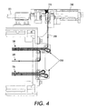
- the spacing of the wire strands to each other positioned between the donor roll and the photoreceptor belt is a critical parameter. This spacing is set by the position of the pulleys assemblies 250 and 252 that are at the end of the donor rolls.
- a wire sensing includes a lead screw 263, flag 260 and switches 261 and 262.
- Mounted on the lead screw is a flag.
- the lead screw has a male thread on the outside diameter and the flag has a female thread in the bore.
- the flag is designed and mounted such that it will not rotate with the lead screw. As the lead screw rotates the flag moves axially along the lead screw.
- This wire module assembly is purchased from a supplier with the wire tensioned. In this design there is no tension adjustment after it is initially set.
- the Wire tension set point ie. 565 ⁇ 25Hz.
- the tension procedure is: mount the wire module assembly to the wire tensioning fixture; attach a brake 301 to the OB end of the take-up spool shaft and set brake to yield a wire tension of 565 ⁇ 25Hz; load approximately 4,200mm of wire onto the take-up spool; string the wire through the wire module and terminate the end of the wire on the supply spool; detach the OB coupling from the take-up spool; turn on the motor so that the wire will wind up on the supply spool.
Landscapes
- Physics & Mathematics (AREA)
- General Physics & Mathematics (AREA)
- Dry Development In Electrophotography (AREA)
Abstract
Description
In a further embodiment said a wire assembly module further includes a stringing system for arranging said wire into plurality of elongated wires with adjacent wires being spaced from and substantially parallel to one another.
In a further embodiment said drive system includes means for supporting said plurality of wires at a preselected tension.
In a further embodiment said plurality of wires contacts said donor member.
When the motor turns it also turns the
Claims (10)
- An apparatus for developing in a development zone a latent image recorded on a surface, including:a housing defining a chamber storing at least a supply of toner therein; a donor member disposed of at least partially in the chamber of said housing and spaced from the surface, said donor member being adapted to rotate about a longitudinal axis to transport toner to the development zone in a region opposed from the surface; anda wire assembly module mounted the development zone and extending in a direction transverse to the longitudinal axis, said wire assembly module including a wire and a drive system for translating portions of the wire in the development zone, and means for electrically biasing said wire to detach toner from said donor member so as to form a toner powder cloud in the development zone with detached toner from the toner cloud developing the latent image.
- An apparatus according to claim 1, wherein said a wire assembly module further includes a stringing system for arranging said wire into plurality of elongated wires with adjacent wires being spaced from and substantially parallel to one another.
- An apparatus according to claim 2, wherein said drive system includes means for supporting said plurality of wires at a preselected tension.
- An apparatus according to claim 2, wherein said plurality of wires contacts said donor member.
- An apparatus according to claim 3, wherein said wire drive system includes a supply spool for holding unused portions of said wire and a take-up spool for holding used portion of said wire.
- An apparatus according to claim 1, wherein said wire drive system includes a controller for sending a control signal to said drive system to translate portions of said wire from said supply spool or take-up spool when desired.
- An apparatus according to claim 6, wherein said controller sends said control signal to said drive system to translate said wire in response to an image fault signal.
- An apparatus according to claim 6, wherein said controller includes a sensor for detecting amount of wire acquired in either said supply spool or said take-up spool.
- An apparatus according to claim 1, wherein adjacent wires are translated in opposite direction from each other.
- An apparatus according to claim 1, wherein said wire rotates about its axis as the wire translate across the donor member.
Applications Claiming Priority (2)
| Application Number | Priority Date | Filing Date | Title |
|---|---|---|---|
| US10/853,811 US7076193B2 (en) | 2004-05-26 | 2004-05-26 | Wire module for developer unit |
| US853811 | 2004-05-26 |
Publications (2)
| Publication Number | Publication Date |
|---|---|
| EP1600827A2 true EP1600827A2 (en) | 2005-11-30 |
| EP1600827A3 EP1600827A3 (en) | 2010-12-29 |
Family
ID=34939968
Family Applications (1)
| Application Number | Title | Priority Date | Filing Date |
|---|---|---|---|
| EP05104457A Withdrawn EP1600827A3 (en) | 2004-05-26 | 2005-05-25 | A wire module for developer unit |
Country Status (2)
| Country | Link |
|---|---|
| US (1) | US7076193B2 (en) |
| EP (1) | EP1600827A3 (en) |
Families Citing this family (3)
| Publication number | Priority date | Publication date | Assignee | Title |
|---|---|---|---|---|
| US20080279596A1 (en) * | 2007-05-09 | 2008-11-13 | Xerox Corporation | Low graininess printing and micr printing with scmb and ea-scmb systems |
| US8442407B2 (en) | 2010-07-27 | 2013-05-14 | Xerox Corporation | Methods, apparatus and systems to control the tribo-electric charge of a toner material associated with a printing development system |
| US8849165B2 (en) * | 2012-05-17 | 2014-09-30 | Xerox Corporation | Wire-wrapped grooved rollers for cleaning action using brush-like system |
Family Cites Families (16)
| Publication number | Priority date | Publication date | Assignee | Title |
|---|---|---|---|---|
| US4033292A (en) * | 1974-11-21 | 1977-07-05 | Xerox Corporation | Apparatus for developing latent electrostatic images |
| US4868600A (en) * | 1988-03-21 | 1989-09-19 | Xerox Corporation | Scavengeless development apparatus for use in highlight color imaging |
| US4984019A (en) * | 1990-02-26 | 1991-01-08 | Xerox Corporation | Electrode wire cleaning |
| JPH04299193A (en) * | 1990-10-29 | 1992-10-22 | Xerox Corp | Stitcher-wire-display unit |
| JPH05281847A (en) * | 1992-03-31 | 1993-10-29 | Fuji Xerox Co Ltd | Developing device |
| JPH0667547A (en) * | 1992-08-20 | 1994-03-11 | Fuji Xerox Co Ltd | Developing device |
| US5321474A (en) * | 1993-03-10 | 1994-06-14 | Xerox Corporation | Active damping of electrode wire vibration in scavengeless development in a xerographic apparatus |
| US5338893A (en) * | 1993-08-16 | 1994-08-16 | Xerox Corporation | Donor roll with electrode spacer for scavengeless development in a xerographic apparatus |
| US5422709A (en) * | 1993-09-17 | 1995-06-06 | Xerox Corporation | Electrode wire grid for developer unit |
| JPH08142388A (en) * | 1994-11-16 | 1996-06-04 | Brother Ind Ltd | Image forming device |
| JPH0926683A (en) * | 1995-07-11 | 1997-01-28 | Toshiba Corp | Charging device and image forming apparatus including the same |
| US5666619A (en) * | 1995-12-06 | 1997-09-09 | Xerox Corporation | Electrode wire support for scavengeless development |
| US5640657A (en) * | 1995-12-06 | 1997-06-17 | Xerox Corporation | Electrode wire twisted loop mounting for scavengeless development |
| US5600416A (en) * | 1995-12-06 | 1997-02-04 | Xerox Corporation | Electrode wire tensioning for scavengeless development |
| US6108504A (en) * | 1999-03-26 | 2000-08-22 | Eastman Kodak Company | Corona wire replenishing mechanism |
| US6181896B1 (en) * | 1999-05-19 | 2001-01-30 | Xerox Corporation | Development housing having improved toner emission control |
-
2004
- 2004-05-26 US US10/853,811 patent/US7076193B2/en not_active Expired - Fee Related
-
2005
- 2005-05-25 EP EP05104457A patent/EP1600827A3/en not_active Withdrawn
Also Published As
| Publication number | Publication date |
|---|---|
| EP1600827A3 (en) | 2010-12-29 |
| US20050265754A1 (en) | 2005-12-01 |
| US7076193B2 (en) | 2006-07-11 |
Similar Documents
| Publication | Publication Date | Title |
|---|---|---|
| US5010368A (en) | Magnetic transport roll for supplying toner or carrier and toner to a donor and magnetic developer roll respectively | |
| EP0426420B1 (en) | Development apparatus | |
| EP0414455A2 (en) | Hybrid development system | |
| EP0601786B1 (en) | Proper charging of donor roll in hybrid development | |
| US5253016A (en) | Contaminant control for scavengeless development in a xerographic apparatus | |
| EP0581562B1 (en) | AC/DC spatially programmable donor roll for xerographic development | |
| EP0559398A2 (en) | Electrode wire mounting for scavengeless development | |
| US9329531B2 (en) | Developing device, image forming unit and image forming apparatus provided with the same | |
| US8086148B2 (en) | Electrophotographic image forming apparatus | |
| JP2002318487A (en) | Developing method, image forming unit and image forming apparatus | |
| US5422709A (en) | Electrode wire grid for developer unit | |
| US6665510B1 (en) | Apparatus and method for reducing ghosting defects in a printing machine | |
| US7076193B2 (en) | Wire module for developer unit | |
| US5204719A (en) | Development system | |
| US7010239B2 (en) | Apparatus and method for cleaning a donor roll | |
| US8849165B2 (en) | Wire-wrapped grooved rollers for cleaning action using brush-like system | |
| JP2007128068A (en) | Electrophotographic development unit with irregular core size auger | |
| US6788904B2 (en) | Climate control system for developer material in a developer housing | |
| US7555246B2 (en) | Development sub-system in-line cleaning system | |
| JP2007128069A (en) | Electrophotographic development unit with irregular pitch auger | |
| US6963704B2 (en) | Heating system for a developer housing | |
| US7428398B2 (en) | Development sub-system in-line cleaning system | |
| US6631250B2 (en) | Developer filtration module | |
| US6088562A (en) | Electrode wire grid for developer unit | |
| US6941089B2 (en) | Heating system for a developer housing |
Legal Events
| Date | Code | Title | Description |
|---|---|---|---|
| PUAI | Public reference made under article 153(3) epc to a published international application that has entered the european phase |
Free format text: ORIGINAL CODE: 0009012 |
|
| AK | Designated contracting states |
Kind code of ref document: A2 Designated state(s): AT BE BG CH CY CZ DE DK EE ES FI FR GB GR HU IE IS IT LI LT LU MC NL PL PT RO SE SI SK TR |
|
| AX | Request for extension of the european patent |
Extension state: AL BA HR LV MK YU |
|
| PUAL | Search report despatched |
Free format text: ORIGINAL CODE: 0009013 |
|
| AK | Designated contracting states |
Kind code of ref document: A3 Designated state(s): AT BE BG CH CY CZ DE DK EE ES FI FR GB GR HU IE IS IT LI LT LU MC NL PL PT RO SE SI SK TR |
|
| AX | Request for extension of the european patent |
Extension state: AL BA HR LV MK YU |
|
| RIC1 | Information provided on ipc code assigned before grant |
Ipc: G03G 15/08 20060101ALI20101122BHEP Ipc: G03G 15/06 20060101AFI20050718BHEP |
|
| 17P | Request for examination filed |
Effective date: 20110629 |
|
| AKX | Designation fees paid |
Designated state(s): DE FR GB |
|
| STAA | Information on the status of an ep patent application or granted ep patent |
Free format text: STATUS: THE APPLICATION IS DEEMED TO BE WITHDRAWN |
|
| 18D | Application deemed to be withdrawn |
Effective date: 20131203 |