EP1600785A1 - NMR detector and NMR spectrometer - Google Patents
NMR detector and NMR spectrometer Download PDFInfo
- Publication number
- EP1600785A1 EP1600785A1 EP05253218A EP05253218A EP1600785A1 EP 1600785 A1 EP1600785 A1 EP 1600785A1 EP 05253218 A EP05253218 A EP 05253218A EP 05253218 A EP05253218 A EP 05253218A EP 1600785 A1 EP1600785 A1 EP 1600785A1
- Authority
- EP
- European Patent Office
- Prior art keywords
- sample
- nmr
- spaces
- segments
- elongated
- Prior art date
- Legal status (The legal status is an assumption and is not a legal conclusion. Google has not performed a legal analysis and makes no representation as to the accuracy of the status listed.)
- Granted
Links
- 238000001514 detection method Methods 0.000 claims abstract description 33
- 239000004020 conductor Substances 0.000 claims abstract description 11
- 238000005481 NMR spectroscopy Methods 0.000 abstract description 71
- 239000000523 sample Substances 0.000 description 110
- 239000011521 glass Substances 0.000 description 8
- 239000003990 capacitor Substances 0.000 description 4
- 230000035945 sensitivity Effects 0.000 description 4
- 230000003068 static effect Effects 0.000 description 4
- 239000012212 insulator Substances 0.000 description 3
- 239000002184 metal Substances 0.000 description 3
- 238000000034 method Methods 0.000 description 3
- 238000000655 nuclear magnetic resonance spectrum Methods 0.000 description 3
- 230000003993 interaction Effects 0.000 description 2
- 238000011835 investigation Methods 0.000 description 2
- 238000003486 chemical etching Methods 0.000 description 1
- 230000007423 decrease Effects 0.000 description 1
- 238000010586 diagram Methods 0.000 description 1
- 238000009792 diffusion process Methods 0.000 description 1
- 230000000694 effects Effects 0.000 description 1
- 238000007496 glass forming Methods 0.000 description 1
- 230000001678 irradiating effect Effects 0.000 description 1
- 239000007788 liquid Substances 0.000 description 1
- 238000004519 manufacturing process Methods 0.000 description 1
- 238000005259 measurement Methods 0.000 description 1
- 239000007787 solid Substances 0.000 description 1
- 238000001228 spectrum Methods 0.000 description 1
- 238000004544 sputter deposition Methods 0.000 description 1
- 239000000758 substrate Substances 0.000 description 1
Images





Classifications
-
- G—PHYSICS
- G01—MEASURING; TESTING
- G01R—MEASURING ELECTRIC VARIABLES; MEASURING MAGNETIC VARIABLES
- G01R33/00—Arrangements or instruments for measuring magnetic variables
- G01R33/20—Arrangements or instruments for measuring magnetic variables involving magnetic resonance
- G01R33/28—Details of apparatus provided for in groups G01R33/44 - G01R33/64
- G01R33/32—Excitation or detection systems, e.g. using radio frequency signals
- G01R33/34—Constructional details, e.g. resonators, specially adapted to MR
- G01R33/341—Constructional details, e.g. resonators, specially adapted to MR comprising surface coils
Definitions
- the present invention relates to an NMR detector used in an NMR spectrometer and to an NMR spectrometer equipped with the NMR detector.
- An NMR spectrometer is an apparatus for gaining an NMR spectrum by placing a sample under investigation within a static magnetic field, irradiating the sample with an RF pulse, and then detecting a weak (feeble) RF signal (NMR signal) emanating from the sample.
- the molecular structure can be analyzed by extracting molecular structural information contained in the spectrum.
- Fig. 1 schematically shows the structure of an NMR spectrometer having an RF oscillator 1 emitting an RF pulse.
- the phase and amplitude of the RF pulse are controlled by a phase controller 2 and an amplitude controller 3 and sent to a power amplifier 4.
- the RF pulse is amplified to a power necessary to excite an NMR signal by the power amplifier 4, and then sent to an NMR probe 6 via a duplexer 5.
- the pulse is directed at a sample under investigation (not shown) placed within the NMR probe 6.
- a weak (feeble) NMR signal emanating from the sample is sent to a preamplifier 7 again via the duplexer 5 and amplified up to a signal intensity permitting reception.
- a receiver 8 converts the frequency of the RF NMR signal amplified by the preamplifier 7 into an audio frequency that can be converted into a digital signal.
- the audio frequency of the NMR signal converted by the receiver 8 is converted into a digital signal by an analog-to-digital (A/D) converter 9 and sent to a control computer 10.
- A/D analog-to-digital
- the computer 10 controls the phase controller 2 and amplitude controller 3, and Fourier-transforms the NMR signal received (accepted) in the time domain.
- the computer automatically corrects the phase of the Fourier-transformed NMR signal. Then, the signal is displayed as an NMR spectrum.
- Fig. 2 shows the structure of the prior art NMR detector.
- NMR probe has the detector 11 in which a detection coil 13 is mounted to emit an RF pulse for exciting a sample 12 to be investigated and to detect an NMR signal emanating from the sample 12.
- the detection coil 13 cooperates with a tuning and matching circuit 14 to constitute an RF resonant circuit.
- This RF resonant circuit sends and receives RF pulse and NMR signal to and from the sample 12 contained in an NMR cell 15 placed within the probe 11.
- the sample contained in the cylindrical NMR cell is in the form of a solution, high sensitivity can be obtained by this method of measurement.
- high sensitivity cannot be obtained.
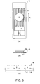
- FIG. 3 shows one example of an NMR detector using a meander coil.
- (a) is a plan view of the detector
- (b) is a cross-sectional view taken in a lateral direction as indicated by the broken line in (a)
- (c) shows the direction of RF magnetic field around coil wires.
- a base plate or substrate 16 forms a sample cell.
- the base plate 16 is made of an insulator such as a glass plate of low dielectric loss to achieve high-sensitivity NMR measurements.
- a meander coil 17 consisting of an elongated conductor repeatedly bent into comb teeth-like straight segments which are regularly spaced from each other and which are uniform in length is mounted on the surface of the base plate 16. The segments at both ends of the meander coil 17 extend downward and are placed opposite to each other under the bent portions.
- a capacitor 18 made of a dielectric is bridged across the opposite ends.
- An LC resonant circuit is formed by the inductance L of the coil 17 and the capacitance C of the capacitor 18.
- the sample space extends planarily.
- the phase of the produced RF magnetic field is rotated. Therefore, there is the problem that if the sample diffuses in a direction crossing the meander coil, the intensityof the NMR signal decreases.
- this effect is conspicuous. Therefore, samples making use of the feature of the meander coil, i.e., high sensitivity to trace amounts of sample, have been limited to solid samples.
- a detector comprising a planar sample cell and a planar detection coil placed close to the sample cell which has a plurality of parallel and elongated sample spaces in connection with each other.
- the detection coil consists of a continuous elongated conductor repeatedly bent into segments each of which has a major axis in the longitudinal direction of each sample space and is substantially parallel to the sample space.
- the sample spaces are filled with a solution sample.
- each of the sample cells has a substantially straight elongated portion.
- the parallel elongated sample spaces are connected in series with each other.
- the parallel elongated sample spaces are connected in parallel with each other.
- an NMR spectrometer equipped with an NMR detector comprising a planar sample cell and a planar detection coil placed close to the sample cell which has a plurality of parallel and elongated sample spaces in connection with each other.
- the detection coil consists of a continuous elongated conductor repeatedly bent into segments each of which has a major axis in the longitudinal direction of each sample space and is substantially parallel to the sample space.
- the sample spaces are filled with a solution sample.
- the elongated sample cells are substantially straight.
- the parallel elongated sample spaces are connected in series with each other.
- the parallel elongated sample spaces are connected in parallel with each other.
- the planar sample cell having the parallel elongated sample spaces and the planar detection coil are placed in proximity to each other.
- the sample spaces are in connection with each other.
- the coil consists of the continuous elongated conductor repeatedly bent into the segments substantially parallel to the sample spaces.
- Each segment has a major axis in the longitudinal direction of each sample space. Therefore, if the amount of the sample contained in the solution sample is quite small, an NMR measurement can be performed well.
- the NMR spectrometer according to the present invention is equipped with the NMR detector comprising the planar sample cell and the planar detection coil placed close to the sample cell which has the plurality of parallel and elongated sample spaces in connection with each other.
- the detection coil consists of the continuous elongated conductor repeatedly bent into the segments each of which has a major axis in the longitudinal direction of each sample space and is substantially parallel to the sample space. Therefore, if the amount of the sample contained in the solution sample is quite small, an NMR measurement can be performed well.
- Fig. 4 shows one NMR detector according to a first embodiment of the present invention.
- the sample cell is shown in (a) and (b) of Fig. 4.
- the detection coil is shown in (c) and (d) of Fig. 4.
- the direction of RF magnetic field around detection coil wires is shown in (e) of Fig. 4.
- (a) is a plan view of the sample cell
- (b) is a cross-sectional view taken in a lateral direction as indicated by the broken line of (a).
- (c) is a plan view of the detection coil.
- (d) is a cross-sectional view taken in a lateral direction as indicated by the broken line of (c).
- (e) is an expanded view of (d).
- a base plate 20 forms a sample cell and is made of an insulator such as a glass plate of low dielectric loss to achieve high-sensitivity NMR measurements.
- the base plate 20 consists of two glass plates 20a and 20b bonded together.
- the repeatedly bent comb teeth-like meandering grooves are formed as sample spaces 21 on one glass plate 20a by a chemical etching process of the glass plate 20a.
- the grooves are regularly spaced from each other and uniform in length.
- the sample spaces 21 consist of the elongated grooves in connection with each other.
- the grooves are channels through which a solution sample may flow.
- Sample ports 22 and 23 for introducing and expelling a liquid sample into and from the sample spaces 21 are formed on the other glass plate 20b.
- the two glass plates 20a and 20b are melted and bonded together based on a microchip fabrication method, thus forming a planar sample cell (seeNon-Patent Reference 1).
- a base plate 24 forms the detection coil.
- the base plate 24 is made of an insulator such as a glass plate of low dielectric loss to achieve high-sensitivity NMR measurements.
- a planar meander coil 25 is formed on the surface of the base plate 24.
- the coil 25 is made of a thin metal film fabricated by sputtering of a metal.
- the metal film forms a continuous elongated conductor that is repeatedly bent into comb teeth-like meandering segments that are regularly spaced from each other and are uniform in length.
- the meander coil 25 has both end portions extending downward and placed opposite to each other under the bent portions of the conductor.
- a capacitor 26 made of a dielectric is bridged across the opposite ends.
- a planar LC resonant circuit is formed by the inductance L of the meander coil 25 and the capacitance C of the capacitor 26.
- Fig. 5 shows the manner in which the base plate 20 of the sample cell and the base plate 24 of the detection coil fabricated in this way are placed in proximity to each other.
- (a) is a plan view of the resulting NMR detector and (b) is a cross-sectional view taken in a lateral direction as indicated by the broken line in (a).
- the base plate 24 of the detection coil is firmly fixed within an NMR probe (not shown).
- the base plate 20 of the sample cell is inserted into the NMR probe (not shown) from outside it and placed close to the coil 25 within the NMR probe such that the meander coil 25 and sample spaces 21 are placed in a positional relationship as shown in Fig. 5, using a retainer tool (not shown).
- the spacing between the sample spaces 21 formed on the base plate 20 is equal to the spacing between the adjacent segments of the meander coil 25 formed on the base plate 24. Therefore, the straight elongated portions of the sample spaces 21 are substantially parallel and exactly opposite to the straight segments of the meander coil 25. Consequently, when radio-frequency waves are supplied to (injected into) the meander coil 25, an RF magnetic field B 1 is produced across the coil as indicated by the arrows along the plane of the paper shown in (e) of Fig. 4.
- the field B 1 is applied to the sample cells (base plate) 20 placed on the meander coil 25.
- the sample spaces 21 are previously filled with a solution sample.
- a static magnetic field B 0 is applied in a direction indicated by the arrow B 0 in (a) of Fig. 4. Because of the interaction with the RF field B 1 , an NMR signal from the solution sample filled in the cells 20 can be observed.
- the base plate 24 on which the meander coil 25 is carried can be removed from the NMR probe (not shown) according to the need.
- the meander coil is appropriately replaced by another meander coil having frequency characteristics corresponding to the different frequency band.
- a sample cell having straight segments longer than the detection coil as shown in Fig. 6 is used.
- This embodiment is characterized in that the bends C of the sample channels are not contained in the NMR detection area.
- plural independent sample spaces through which plural samples can flow are formed in one sample cell as shown in Fig. 7. This makes it possible to measure plural samples at the same time. Furthermore, plural samples can be detected in turn without the sample cell being removed from the NMR measurement portion.
- the straight elongated portions of the sample spaces 21 are exactly opposite to the straight segments of the detection coil 25.
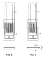
- the straight elongated portions of the sample spaces 21 may be staggered relative to the straight segments of the detection coil 25 as shown in Fig. 8.
- the spacing B between the grooves in the sample spaces 21 is equal to the spacing C between the adjacent segments of the detection coil 25. As shown in Fig. 9, the spacing B between the grooves in the sample spaces 21 may be different from the spacing C between the adjacent segments of the detection coil 25. In this case, the distance A between the sample space surface and the detection coil surface is set to approximately 0.8 times the spacing C between the segments of the detection coil 25. Consequently, the same strength of RF magnetic field is applied to all the sample spaces 21. It is possible that every sample space 21 acts as the same detection space.
- Embodiments 1 to 5 the plural elongated sample spaces 21 are connected in series. This meander sample cell is constructed as if one channel were repeatedly bent. The plural elongated sample spaces 21 may be connected in parallel with each other within the base plate 20 as shown in Fig. 10.
- NMR detectors according to the present invention can be widely used in NMR instruments.
Landscapes
- Physics & Mathematics (AREA)
- Condensed Matter Physics & Semiconductors (AREA)
- General Physics & Mathematics (AREA)
- Investigating Or Analyzing Materials By The Use Of Magnetic Means (AREA)
Abstract
Description
- The present invention relates to an NMR detector used in an NMR spectrometer and to an NMR spectrometer equipped with the NMR detector.
- An NMR spectrometer is an apparatus for gaining an NMR spectrum by placing a sample under investigation within a static magnetic field, irradiating the sample with an RF pulse, and then detecting a weak (feeble) RF signal (NMR signal) emanating from the sample. The molecular structure can be analyzed by extracting molecular structural information contained in the spectrum.
- Fig. 1 schematically shows the structure of an NMR spectrometer having an RF oscillator 1 emitting an RF pulse. The phase and amplitude of the RF pulse are controlled by a phase controller 2 and an amplitude controller 3 and sent to a power amplifier 4.
- The RF pulse is amplified to a power necessary to excite an NMR signal by the power amplifier 4, and then sent to an NMR probe 6 via a
duplexer 5. The pulse is directed at a sample under investigation (not shown) placed within the NMR probe 6. After the RF irradiation, a weak (feeble) NMR signal emanating from the sample is sent to a preamplifier 7 again via theduplexer 5 and amplified up to a signal intensity permitting reception. - A
receiver 8 converts the frequency of the RF NMR signal amplified by the preamplifier 7 into an audio frequency that can be converted into a digital signal. The audio frequency of the NMR signal converted by thereceiver 8 is converted into a digital signal by an analog-to-digital (A/D)converter 9 and sent to acontrol computer 10. - The
computer 10 controls the phase controller 2 and amplitude controller 3, and Fourier-transforms the NMR signal received (accepted) in the time domain. The computer automatically corrects the phase of the Fourier-transformed NMR signal. Then, the signal is displayed as an NMR spectrum. - Fig. 2 shows the structure of the prior art NMR detector. NMR probe has the
detector 11 in which adetection coil 13 is mounted to emit an RF pulse for exciting asample 12 to be investigated and to detect an NMR signal emanating from thesample 12. Thedetection coil 13 cooperates with a tuning and matchingcircuit 14 to constitute an RF resonant circuit. This RF resonant circuit sends and receives RF pulse and NMR signal to and from thesample 12 contained in anNMR cell 15 placed within theprobe 11. Where the sample contained in the cylindrical NMR cell is in the form of a solution, high sensitivity can be obtained by this method of measurement. However, there is the problem that where the sample assumes a planar form, high sensitivity cannot be obtained. - In recent years, an NMR detector using a meander coil has been proposed to detect an NMR signal originated from a planar sample at high sensitivity (Patent Reference 1). Fig. 3 shows one example of an NMR detector using a meander coil. In Fig. 3, (a) is a plan view of the detector, (b) is a cross-sectional view taken in a lateral direction as indicated by the broken line in (a), and (c) shows the direction of RF magnetic field around coil wires. In Fig. 3, a base plate or
substrate 16 forms a sample cell. Thebase plate 16 is made of an insulator such as a glass plate of low dielectric loss to achieve high-sensitivity NMR measurements. - A
meander coil 17 consisting of an elongated conductor repeatedly bent into comb teeth-like straight segments which are regularly spaced from each other and which are uniform in length is mounted on the surface of thebase plate 16. The segments at both ends of themeander coil 17 extend downward and are placed opposite to each other under the bent portions. Acapacitor 18 made of a dielectric is bridged across the opposite ends. An LC resonant circuit is formed by the inductance L of thecoil 17 and the capacitance C of thecapacitor 18. Thus, if radio waves are supplied to (injected into) themeander coil 17, an RF magnetic field B1 is produced across the meander coil as indicated by the arrows in (c) Fig. 3. An RF magnetic field B1 is applied to aplanar sample 19 placed on thecoil 17. If a static magnetic field B0 is previously applied parallel to the plane of the paper, an NMR signal from thesample 19 can be observed by interaction with the RF magnetic field B1. - [Non-Patent Reference 1] Published Technical Disclosure 2004-502547 of Japan Institute of Invention and Innovation
- In the prior art, the sample space extends planarily. In the sample space, in directions crossing the meander coil, the phase of the produced RF magnetic field is rotated. Therefore, there is the problem that if the sample diffuses in a direction crossing the meander coil, the intensityof the NMR signal decreases. Especially, in a case where the spacing between the adjacent segments of the bent conductor, or meander coil, is small, this effect is conspicuous. Therefore, samples making use of the feature of the meander coil, i.e., high sensitivity to trace amounts of sample, have been limited to solid samples.
- In view of the foregoing, it would be desirable to provide an NMR detector which makes use of the merit of a meander coil and permits good NMR measurements of even trace amounts of samples in solution (solution samples).
- In accordance with a first aspect of the present invention, there is provided a detector comprising a planar sample cell and a planar detection coil placed close to the sample cell which has a plurality of parallel and elongated sample spaces in connection with each other. The detection coil consists of a continuous elongated conductor repeatedly bent into segments each of which has a major axis in the longitudinal direction of each sample space and is substantially parallel to the sample space.
- In one embodiment of the invention, the sample spaces are filled with a solution sample.
- In another embodiment of the invention, each of the sample cells has a substantially straight elongated portion.
- In a further embodiment of the invention, the parallel elongated sample spaces are connected in series with each other.
- In a yet other embodiment of the invention, the parallel elongated sample spaces are connected in parallel with each other.
- In accordance with a second aspect of the present invention, there is provided an NMR spectrometer equipped with an NMR detector comprising a planar sample cell and a planar detection coil placed close to the sample cell which has a plurality of parallel and elongated sample spaces in connection with each other. The detection coil consists of a continuous elongated conductor repeatedly bent into segments each of which has a major axis in the longitudinal direction of each sample space and is substantially parallel to the sample space.
- In one embodiment of the invention, the sample spaces are filled with a solution sample.
- In another embodiment of the invention, the elongated sample cells are substantially straight.
- In a further embodiment of the invention, the parallel elongated sample spaces are connected in series with each other.
- In a yet other embodiment of the invention, the parallel elongated sample spaces are connected in parallel with each other.
- In the NMR detector according to the present invention, the planar sample cell having the parallel elongated sample spaces and the planar detection coil are placed in proximity to each other. The sample spaces are in connection with each other. The coil consists of the continuous elongated conductor repeatedly bent into the segments substantially parallel to the sample spaces. Each segment has a major axis in the longitudinal direction of each sample space. Therefore, if the amount of the sample contained in the solution sample is quite small, an NMR measurement can be performed well.
- The NMR spectrometer according to the present invention is equipped with the NMR detector comprising the planar sample cell and the planar detection coil placed close to the sample cell which has the plurality of parallel and elongated sample spaces in connection with each other. The detection coil consists of the continuous elongated conductor repeatedly bent into the segments each of which has a major axis in the longitudinal direction of each sample space and is substantially parallel to the sample space. Therefore, if the amount of the sample contained in the solution sample is quite small, an NMR measurement can be performed well.
- Other preferred embodiments of the invention will appear in the course of the description thereof, which follows.
-
- Fig. 1 is a block diagram of the prior art NMR spectrometer;
- Fig. 2 is a schematic vertical cross section of the prior art NMR detector;
- Fig. 3 shows the prior art meander coil;
- Fig. 4 shows one NMR detector according to one embodiment of the present invention;
- Fig. 5 shows another NMR detector according to one embodiment of the invention;
- Fig. 6 shows a further NMR detector according to one embodiment of the invention;
- Fig. 7 shows a yet other NMR detector according to one embodiment of the invention;
- Fig. 8 shows a still other NMR detector according to one embodiment of the invention;
- Fig. 9 shows an additional NMR detector according to one embodiment of the invention; and
- Fig. 10 shows a still further NMR detector according to one embodiment of the invention.
-
- Seven embodiments of the present invention are hereinafter described with reference to the accompanying drawings.
- Fig. 4 shows one NMR detector according to a first embodiment of the present invention. The sample cell is shown in (a) and (b) of Fig. 4. The detection coil is shown in (c) and (d) of Fig. 4. The direction of RF magnetic field around detection coil wires is shown in (e) of Fig. 4. In Fig. 4, (a) is a plan view of the sample cell, and (b) is a cross-sectional view taken in a lateral direction as indicated by the broken line of (a). (c) is a plan view of the detection coil. (d) is a cross-sectional view taken in a lateral direction as indicated by the broken line of (c). (e) is an expanded view of (d).
- In (a) of Fig. 4, a
base plate 20 forms a sample cell and is made of an insulator such as a glass plate of low dielectric loss to achieve high-sensitivity NMR measurements. As shown in (b) of Fig. 4, thebase plate 20 consists of twoglass plates sample spaces 21 on oneglass plate 20a by a chemical etching process of theglass plate 20a. The grooves are regularly spaced from each other and uniform in length. Thesample spaces 21 consist of the elongated grooves in connection with each other. The grooves are channels through which a solution sample may flow.Sample ports sample spaces 21 are formed on theother glass plate 20b. The twoglass plates - In (c) of Fig. 4, a
base plate 24 forms the detection coil. Thebase plate 24 is made of an insulator such as a glass plate of low dielectric loss to achieve high-sensitivity NMR measurements. Aplanar meander coil 25 is formed on the surface of thebase plate 24. Thecoil 25 is made of a thin metal film fabricated by sputtering of a metal. The metal film forms a continuous elongated conductor that is repeatedly bent into comb teeth-like meandering segments that are regularly spaced from each other and are uniform in length. Themeander coil 25 has both end portions extending downward and placed opposite to each other under the bent portions of the conductor. Acapacitor 26 made of a dielectric is bridged across the opposite ends. Thus, a planar LC resonant circuit is formed by the inductance L of themeander coil 25 and the capacitance C of thecapacitor 26. - Fig. 5 shows the manner in which the
base plate 20 of the sample cell and thebase plate 24 of the detection coil fabricated in this way are placed in proximity to each other. In Fig. 5, (a) is a plan view of the resulting NMR detector and (b) is a cross-sectional view taken in a lateral direction as indicated by the broken line in (a). - The
base plate 24 of the detection coil is firmly fixed within an NMR probe (not shown). On the other hand, thebase plate 20 of the sample cell is inserted into the NMR probe (not shown) from outside it and placed close to thecoil 25 within the NMR probe such that themeander coil 25 andsample spaces 21 are placed in a positional relationship as shown in Fig. 5, using a retainer tool (not shown). - As can be seen from the figure, the spacing between the
sample spaces 21 formed on thebase plate 20 is equal to the spacing between the adjacent segments of themeander coil 25 formed on thebase plate 24. Therefore, the straight elongated portions of thesample spaces 21 are substantially parallel and exactly opposite to the straight segments of themeander coil 25. Consequently, when radio-frequency waves are supplied to (injected into) themeander coil 25, an RF magnetic field B1 is produced across the coil as indicated by the arrows along the plane of the paper shown in (e) of Fig. 4. The field B1 is applied to the sample cells (base plate) 20 placed on themeander coil 25. Thesample spaces 21 are previously filled with a solution sample. Also, a static magnetic field B0 is applied in a direction indicated by the arrow B0 in (a) of Fig. 4. Because of the interaction with the RF field B1, an NMR signal from the solution sample filled in thecells 20 can be observed. - At this time, the width W of the sample spaces taken in a direction crossing the meander coil is limited. Let B be the spacing between the adjacent segments of the meander coil in (b) of Fig. 4. A variation in the phase of a signal due to diffusion of the sample is less than 180°×W/B. Attenuation of the signal is suppressed.
- In (b) of Fig. 5, if the distance A between the coil surface and the sample surface is set to approximately 0.8 times the spacing B between the adjacent segments of the coil, the same strength of RF magnetic field is applied also to the bends C of the sample channels. Hence, the bends act as areas detected under the same conditions (see Patent Reference 1).
- The
base plate 24 on which themeander coil 25 is carried can be removed from the NMR probe (not shown) according to the need. When an NMR measurement is performed in a different frequency band, the meander coil is appropriately replaced by another meander coil having frequency characteristics corresponding to the different frequency band. - In this embodiment, a sample cell having straight segments longer than the detection coil as shown in Fig. 6 is used. This embodiment is characterized in that the bends C of the sample channels are not contained in the NMR detection area.
- Accordingly, in this structure, in the areas located outside the detection area, no NMR signal can be detected. Where there is a difference between the magnetic susceptibility of the sample and the magnetic susceptibility of the glass forming the sample cell, the homogeneity of the static magnetic field in the detection area can be enhanced by intentionally separating the bends C of the channels from the detection area. As a result, the linewidth of the NMR spectrum can be narrowed. Hence, the resolution can be improved.
- In this embodiment, plural independent sample spaces through which plural samples can flow are formed in one sample cell as shown in Fig. 7. This makes it possible to measure plural samples at the same time. Furthermore, plural samples can be detected in turn without the sample cell being removed from the NMR measurement portion.
- This can be used in the following two ways:
- (a) A
first sample area 27 and asecond sample area 28 are filled with different samples. Resulting NMR signals are measured at the same time. - (b) A first sample is loaded into the
first sample area 27. The resulting NMR signal is measured and then the first sample is extracted. Thereafter, the position of the sample cell is shifted. A second sample is loaded into thesecond sample area 28. Then, the resulting NMR signal is measured. -
- In Embodiments 1 to 3, the straight elongated portions of the
sample spaces 21 are exactly opposite to the straight segments of thedetection coil 25. Alternatively, the straight elongated portions of thesample spaces 21 may be staggered relative to the straight segments of thedetection coil 25 as shown in Fig. 8. - In Embodiments 1 to 4, the spacing B between the grooves in the
sample spaces 21 is equal to the spacing C between the adjacent segments of thedetection coil 25. As shown in Fig. 9, the spacing B between the grooves in thesample spaces 21 may be different from the spacing C between the adjacent segments of thedetection coil 25. In this case, the distance A between the sample space surface and the detection coil surface is set to approximately 0.8 times the spacing C between the segments of thedetection coil 25. Consequently, the same strength of RF magnetic field is applied to all thesample spaces 21. It is possible that everysample space 21 acts as the same detection space. - In Embodiments 1 to 5, the plural
elongated sample spaces 21 are connected in series. This meander sample cell is constructed as if one channel were repeatedly bent. The pluralelongated sample spaces 21 may be connected in parallel with each other within thebase plate 20 as shown in Fig. 10. - By incorporating an NMR detector as shown in any one of Embodiments 1 to 6 into the existing NMR spectrometer, a novel type of NMR spectrometer capable of performing NMR measurements well if the amount of sample in the solution sample is quite small can be obtained.
- NMR detectors according to the present invention can be widely used in NMR instruments.
Claims (10)
- An NMR detector comprising:a substantially planar sample cell having a plurality of substantially parallel, elongated sample spaces in connection with each other; anda substantially planar detection coil disposed close to the sample cell and consisting of a continuous elongated conductor repeatedly bent into segments which are substantially parallel to said sample spaces, each of the segments having a major axis in a longitudinal direction of each of the sample spaces.
- An NMR detector as set forth in claim 1, wherein said sample spaces are filled with a solution sample.
- An NMR detector as set forth in claim 1 or 2, wherein each of said sample spaces has a substantially straight elongated portion.
- An NMR detector as set forth in any preceding claim, wherein said parallel, elongated sample spaces are connected in series with each other.
- An NMR detector as set forth in any of claims 1 to 3, wherein said parallel, elongated sample spaces are connected in parallel with each other.
- An NMR spectrometer equipped with an NMR detector, said NMR detector comprising:a substantially planar sample cell having a plurality of substantially parallel, elongated sample spaces in connection with each other; anda substantially planar detection coil disposed close to the sample cell and consisting of a continuous elongated conductor repeatedly bent into segments which are substantially parallel to said sample spaces, each of the segments having a major axis in a longitudinal direction of each of the sample spaces.
- An NMR spectrometer as set forth in claim 6, wherein said sample spaces are filled with a solution sample.
- An NMR spectrometer as set forth in claim 6 or 7, wherein each of said sample spaces has a substantially straight elongated portion.
- An NMR spectrometer as set forth in any of claims 6 to 8, wherein said parallel, elongated sample spaces are connected in series with each other.
- An NMR spectrometer as set forth in any of claims 6 to 8, wherein said parallel, elongated sample spaces are connected in parallel with each other.
Applications Claiming Priority (4)
| Application Number | Priority Date | Filing Date | Title |
|---|---|---|---|
| JP2004154401 | 2004-05-25 | ||
| JP2004154401 | 2004-05-25 | ||
| JP2005128158 | 2005-04-26 | ||
| JP2005128158A JP4607651B2 (en) | 2004-05-25 | 2005-04-26 | NMR detector and NMR apparatus |
Publications (2)
| Publication Number | Publication Date |
|---|---|
| EP1600785A1 true EP1600785A1 (en) | 2005-11-30 |
| EP1600785B1 EP1600785B1 (en) | 2008-08-13 |
Family
ID=34941452
Family Applications (1)
| Application Number | Title | Priority Date | Filing Date |
|---|---|---|---|
| EP05253218A Expired - Lifetime EP1600785B1 (en) | 2004-05-25 | 2005-05-25 | NMR detector and NMR spectrometer |
Country Status (4)
| Country | Link |
|---|---|
| US (1) | US7180295B2 (en) |
| EP (1) | EP1600785B1 (en) |
| JP (1) | JP4607651B2 (en) |
| DE (1) | DE602005008816D1 (en) |
Cited By (1)
| Publication number | Priority date | Publication date | Assignee | Title |
|---|---|---|---|---|
| US11714146B2 (en) | 2020-09-29 | 2023-08-01 | Socpra Sciences Et Genie S.E.C. | Nuclear magnetic resonance spectrometer, method of operation, and probe therefore |
Families Citing this family (2)
| Publication number | Priority date | Publication date | Assignee | Title |
|---|---|---|---|---|
| EP1918730B1 (en) * | 2006-10-26 | 2013-05-15 | Bruker BioSpin AG | NMR apparatus with a microfluidic NMR chip |
| WO2012118442A1 (en) * | 2011-02-28 | 2012-09-07 | Massachusetts Institute Of Technology | Biosensor, palm-sized device and method based on magnetic resonance relaxometry |
Citations (1)
| Publication number | Priority date | Publication date | Assignee | Title |
|---|---|---|---|---|
| US6326787B1 (en) * | 1999-06-10 | 2001-12-04 | Sandia National Laboratories | NMR of thin layers using a meanderline surface coil |
Family Cites Families (15)
| Publication number | Priority date | Publication date | Assignee | Title |
|---|---|---|---|---|
| US3153756A (en) * | 1955-05-31 | 1964-10-20 | Exxon Research Engineering Co | Process for conducting quantitative analyses |
| US3048772A (en) * | 1955-05-31 | 1962-08-07 | Exxon Research Engineering Co | Process for conducting quantitative analyses |
| US3038115A (en) * | 1957-02-11 | 1962-06-05 | Socony Mobil Oil Co Inc | Orientation of nuclear magnetic resonance samples |
| US3254212A (en) * | 1962-01-12 | 1966-05-31 | Continental Oil Co | Apparatus for determining the concentration of aluminum in hydrocarbon streams by the use of k-capture radioactivity |
| DE4013111C2 (en) * | 1990-04-25 | 1994-05-26 | Spectrospin Ag | RF receiver coil arrangement for NMR spectrometers |
| US5585723A (en) * | 1995-03-23 | 1996-12-17 | Conductus, Inc. | Inductively coupled superconducting coil assembly |
| US5469061A (en) * | 1993-04-02 | 1995-11-21 | Battelle Memorial Institute | Spectrometer capillary vessel and method of making same |
| US5552709A (en) * | 1995-10-17 | 1996-09-03 | Varian Associates, Inc. | NMR sample cell |
| US6201392B1 (en) * | 1997-11-07 | 2001-03-13 | Varian, Inc. | Coplanar RF probe coil arrangement for multifrequency excitation |
| US5986453A (en) * | 1997-11-07 | 1999-11-16 | Varian, Inc. | AC magnetic susceptibility control of superconducting materials in nuclear magnetic resonance (NMR) probes |
| US6054855A (en) * | 1997-11-07 | 2000-04-25 | Varian, Inc. | Magnetic susceptibility control of superconducting materials in nuclear magnetic resonance (NMR) probes |
| US6194900B1 (en) * | 1998-06-19 | 2001-02-27 | Agilent Technologies, Inc. | Integrated miniaturized device for processing and NMR detection of liquid phase samples |
| DE19956977A1 (en) * | 1998-11-27 | 2000-07-20 | Jeol Ltd | Nuclear Magnetic Resonance probe uses glass epoxy or quartz glass base to reduce background signals |
| JP3687846B2 (en) * | 2001-10-29 | 2005-08-24 | 独立行政法人産業技術総合研究所 | Double tube structure type magnetic resonance sample container |
| US6917201B2 (en) * | 2002-12-09 | 2005-07-12 | Varian, Inc. | Squashed liquid NMR sample tubes and RF coils |
-
2005
- 2005-04-26 JP JP2005128158A patent/JP4607651B2/en not_active Expired - Fee Related
- 2005-05-25 EP EP05253218A patent/EP1600785B1/en not_active Expired - Lifetime
- 2005-05-25 DE DE602005008816T patent/DE602005008816D1/en not_active Expired - Lifetime
- 2005-05-25 US US11/137,858 patent/US7180295B2/en not_active Expired - Fee Related
Patent Citations (1)
| Publication number | Priority date | Publication date | Assignee | Title |
|---|---|---|---|---|
| US6326787B1 (en) * | 1999-06-10 | 2001-12-04 | Sandia National Laboratories | NMR of thin layers using a meanderline surface coil |
Non-Patent Citations (3)
| Title |
|---|
| BUESS M L ET AL: "NQR DETECTION USING A MEANDERLINE SURFACE COIL", JOURNAL OF MAGNETIC RESONANCE, ACADEMIC PRESS, ORLANDO, FL, US, vol. 92, no. 2, 1 April 1991 (1991-04-01), pages 348 - 362, XP000220344, ISSN: 1090-7807 * |
| FARRAR C T ET AL: "Use of cylindrical meanderline catheter coils for intravascular imaging", PROCEEDINGS OF THE INTERNATIONAL SOCIETY FOR MAGNETIC RESONANCE IN MEDICINE. SCIENTIFIC MEETING AND EXHIBITION, 10 May 2003 (2003-05-10), pages 2648, XP002276046 * |
| WANG Z ET AL: "FLOW MEASUREMENT BY DOPPLER SHIFT NUCLEAR MAGNETIC RESONANCE", JOURNAL OF CHEMICAL PHYSICS, NEW YORK, NY, US, vol. 90, no. 6, 15 March 1989 (1989-03-15), pages 3396 - 3398, XP008052098, ISSN: 0021-9606 * |
Cited By (1)
| Publication number | Priority date | Publication date | Assignee | Title |
|---|---|---|---|---|
| US11714146B2 (en) | 2020-09-29 | 2023-08-01 | Socpra Sciences Et Genie S.E.C. | Nuclear magnetic resonance spectrometer, method of operation, and probe therefore |
Also Published As
| Publication number | Publication date |
|---|---|
| JP4607651B2 (en) | 2011-01-05 |
| US20060006869A1 (en) | 2006-01-12 |
| EP1600785B1 (en) | 2008-08-13 |
| DE602005008816D1 (en) | 2008-09-25 |
| US7180295B2 (en) | 2007-02-20 |
| JP2006010679A (en) | 2006-01-12 |
Similar Documents
| Publication | Publication Date | Title |
|---|---|---|
| US6456072B1 (en) | Method and apparatus for simultaneous acquisition of high resolution NMR spectra from multiple samples | |
| US6664708B2 (en) | Method and device for non-contact detection of external electric or magnetic fields | |
| US6696838B2 (en) | Nuclear magnetic resonance analysis of multiple samples | |
| US7271592B1 (en) | Toroid cavity/coil NMR multi-detector | |
| EP2875369B1 (en) | Crossed-loop resonators | |
| US8773125B2 (en) | Microcoil NMR for downhole microfluidics platform | |
| US7095230B2 (en) | NMR probe for material analysis | |
| EP2486416B1 (en) | Dual-mode microwave resonator device and method of electron spin resonance measurement | |
| US7132829B2 (en) | NMR RF coils with improved low-frequency efficiency | |
| EP0586583A1 (en) | Detection of explosives by nuclear quadrupole resonance | |
| US7872476B2 (en) | NMR probe | |
| EP2015093A2 (en) | NMR probe | |
| EP1600785B1 (en) | NMR detector and NMR spectrometer | |
| EP2799849A1 (en) | Nmr imaging device and nmr imaging method | |
| KR101038562B1 (en) | Solid-state nuclear magnetic resonance probe device and its circuit | |
| JP6517901B2 (en) | HF Resonator Assembly, Measurement Probe, and Magnetic Resonance Device | |
| JP2009264972A (en) | Antenna for nqr inspection and nqr inspection device using the same | |
| US7764070B2 (en) | Bio molecular detection apparatus and method thereof | |
| JP2005331271A (en) | NMR cell and probe | |
| US20170030985A1 (en) | Device for Subdividing Magnetic Field and Simultaneous Detection of Magnetic Resonance Signals from Multiple Sample Compartments | |
| US10782256B2 (en) | NMR method for detecting and quantifying individual analytes in liquid analyte mixtures | |
| EP4478063A1 (en) | Apparatus for characterising a signal, method of characterising a signal | |
| SU1520415A1 (en) | Method of generating reference signals in spectra of nuclear magnetic resonance of high resolution | |
| US8744809B2 (en) | System and method for sensing of a nuclear quadrupole resonance | |
| WO2004083883A1 (en) | Magnetoinductive waveguide |
Legal Events
| Date | Code | Title | Description |
|---|---|---|---|
| PUAI | Public reference made under article 153(3) epc to a published international application that has entered the european phase |
Free format text: ORIGINAL CODE: 0009012 |
|
| AK | Designated contracting states |
Kind code of ref document: A1 Designated state(s): AT BE BG CH CY CZ DE DK EE ES FI FR GB GR HU IE IS IT LI LT LU MC NL PL PT RO SE SI SK TR |
|
| AX | Request for extension of the european patent |
Extension state: AL BA HR LV MK YU |
|
| 17P | Request for examination filed |
Effective date: 20060113 |
|
| AKX | Designation fees paid |
Designated state(s): DE GB |
|
| 17Q | First examination report despatched |
Effective date: 20070522 |
|
| GRAP | Despatch of communication of intention to grant a patent |
Free format text: ORIGINAL CODE: EPIDOSNIGR1 |
|
| GRAS | Grant fee paid |
Free format text: ORIGINAL CODE: EPIDOSNIGR3 |
|
| GRAA | (expected) grant |
Free format text: ORIGINAL CODE: 0009210 |
|
| AK | Designated contracting states |
Kind code of ref document: B1 Designated state(s): DE GB |
|
| REG | Reference to a national code |
Ref country code: GB Ref legal event code: FG4D |
|
| REF | Corresponds to: |
Ref document number: 602005008816 Country of ref document: DE Date of ref document: 20080925 Kind code of ref document: P |
|
| PLBE | No opposition filed within time limit |
Free format text: ORIGINAL CODE: 0009261 |
|
| STAA | Information on the status of an ep patent application or granted ep patent |
Free format text: STATUS: NO OPPOSITION FILED WITHIN TIME LIMIT |
|
| 26N | No opposition filed |
Effective date: 20090514 |
|
| PGFP | Annual fee paid to national office [announced via postgrant information from national office to epo] |
Ref country code: GB Payment date: 20110525 Year of fee payment: 7 |
|
| PGFP | Annual fee paid to national office [announced via postgrant information from national office to epo] |
Ref country code: DE Payment date: 20110518 Year of fee payment: 7 |
|
| GBPC | Gb: european patent ceased through non-payment of renewal fee |
Effective date: 20120525 |
|
| REG | Reference to a national code |
Ref country code: DE Ref legal event code: R119 Ref document number: 602005008816 Country of ref document: DE Effective date: 20121201 |
|
| PG25 | Lapsed in a contracting state [announced via postgrant information from national office to epo] |
Ref country code: GB Free format text: LAPSE BECAUSE OF NON-PAYMENT OF DUE FEES Effective date: 20120525 |
|
| PG25 | Lapsed in a contracting state [announced via postgrant information from national office to epo] |
Ref country code: DE Free format text: LAPSE BECAUSE OF NON-PAYMENT OF DUE FEES Effective date: 20121201 |