FIELD OF THE INVENTION
The present invention relates generally to non-destructive inspection
techniques for evaluating coatings on a substrate. More specifically, the present
invention relates to utilizing electrochemical impedance spectroscopy to assess
thermally grown oxides on gas turbine engine components, and probes for use
therewith.
BACKGROUND OF THE INVENTION
Gas turbine engines have long been used to convert chemical potential energy,
in the form of fuel, to thermal energy, and then to mechanical energy for use in
propelling aircraft, generating electric power, pumping fluids, etc. The efficiency of
gas turbine engines increases with increasing operating temperatures. Therefore,
there is a large incentive to raise the combustion and exhaust temperatures of such
engines. However, the metallic materials that are used in the hot-section components
of such engines operate at temperatures very near the upper limits of their thermal
stability. In fact, in the hottest section of modem gas turbine engines, metallic
materials are utilized in hot gas paths at temperatures above their melting points.
These metallic materials survive such temperatures only because they are cooled in
some way, and/or because they comprise thermal barrier coatings (TBCs) thereon that
lower the thermal conductivity of the component, thereby allowing the components to
be operated at higher temperatures.
Typical thermal barrier coatings on gas turbine engine components (i.e.,
turbine blades, turbine vanes, seals, combustor panels, etc.) generally comprise a
metallic bondcoat and a ceramic topcoat. The metallic bondcoat may comprise a
MCrAlY alloy, where M is Ni, Co, or NiCo, which is applied directly overlying the
metallic substrate in any suitable manner. The thermally insulating ceramic topcoat
may comprise yttria stabilized zirconia, which is applied overlying the metallic
bondcoat layer in any suitable manner. While this topcoat layer is being deposited, a
thermally grown oxide (TGO) layer, such as alumina, forms on the metallic bondcoat
layer, between the metallic bondcoat and the ceramic topcoat. As time at temperature
and number of cycles increases, this TGO layer grows in thickness, and eventually
reaches a critical value, followed by failure of the coating. Failure of the coating
exposes the underlying alloy material of the gas turbine engine component to extreme
temperatures, which accelerates the oxidation and/or corrosion of the alloy material,
leading to the component's failure. Since this TGO layer is such an important factor
in controlling the degradation of TBCs, determining the degree of degradation of
TBCs is essential for predicting the remaining lifetime and failure of TBCs on gas
turbine engine components. Additionally, defects may be created while the
components are being coated. Therefore, it would be beneficial to have a quick and
easy way to non-destructively assess coating quality in the production line, or in a
repair or maintenance environment.
There are currently a variety of non-destructive methods that can be utilized to
measure or evaluate the thickness and quality of a TGO layer on a component. Such
methods generally measure or estimate a coating thickness by determining the change
in some physical characteristic that does not require destruction of the coating or
coated component. Non-destructive methods include methods such as: eddy current
methods, laser fluorescence, photoluminescence, smart coatings, acoustic waveguide
sensing, and magnetic methods, among others. Eddy current methods utilize a drive
coil to induce eddy currents within the coated component being tested, so that
secondary magnetic fields resulting from the induced eddy currents can then be
detected by a sensing coil. Laser fluorescence involves shining an argon laser beam
on a ceramic topcoat layer and passing it therethrough to reach the TGO, which then
fluoresces, emitting fluorescent light out through the topcoat and to a detector.
Photoluminescence involves doping a coating with a photoluminescent material,
directing an exciting radiation at the coating, and detecting variations in the intensity
of a characteristic monolithic phase peak in the emission spectrum of the
photoluminescent material. Smart coatings are coatings that are doped with chemical
taggants that can indicate the degree of wear and damage of a coated component
during operation, or that can be detected in downstream exhaust gases as the coating
deteriorates. Acoustic waveguide sensing involves detecting the variations in the
magnitude and velocity of the acoustic waves that pass through a coating as it
deteriorates. Magnetic methods involve utilizing nonlinear harmonics techniques to
determine the degradation of a coating.
It has recently been discovered that electrochemical impedance spectroscopy
(EIS) can be utilized as a non-destructive inspection technique to measure or estimate
the thickness of a TGO layer on a gas turbine engine component, thereby allowing the
quality of the TBC to be assessed. Since yttria stabilized zirconia is an ionic
conductor, and TGO is typically an insulator, EIS can be used to measure impedance
spectra of TBCs on gas turbine engine components, and compositional or
microstructural changes in the TGO can be determined therefrom. Commonly-owned
U. S. Application Serial No. 10/417,032 (Published United States Patent Application
2004/0207413) discloses the specifics of how EIS can be utilized in such a manner,
and the application is hereby incorporated in full by reference.
Existing EIS probes are not ideal for assessing TBCs on gas turbine engine
components. Many existing EIS probes are designed for laboratory use, and as such,
they are large and do not easily lend themselves to a production, repair or
maintenance environment. Additionally, existing EIS probes generally require the
part being measured to be fixtured, and existing probes cannot make measurements on
complex surfaces. As many existing EIS probes are either grossly inadequate for our
purposes, or comprise expensive laboratory equipment that cannot be easily and
portably used in a production, repair or maintenance environment, it would be
desirable to have new EIS probes that allow the thickness, quality, structural integrity,
degree of degradation, and/or remaining lifetime of TBCs to be assessed, and/or that
allow the presence of mixed oxides in the TGO layer to be determined. Ideally, these
probes would allow quick and easy non-destructive assessments of coatings on gas
engine turbine components to be made so that poor quality TBCs can be repaired or
replaced before damage to the underlying component occurs.
SUMMARY OF THE INVENTION
Accordingly, the above-identified shortcomings of existing EIS probes are
overcome by embodiments of the present invention, which relates to novel EIS probe
designs that can be used to assess the thickness, quality, structural integrity, degree of
degradation, and/or remaining lifetime of a thermal barrier coating system, and/or that
allow the presence of mixed oxides in a thermally grown oxide layer to be
determined. The probes of this invention are much smaller than existing EIS probes
and they allow measurements to be made on complex surfaces in a production, repair
and/or maintenance environment. These probes make it quick and easy to perform
non-destructive quality control checks on coated components so that poor quality
TBCs can be identified and repaired or replaced before damage to the underlying
component occurs. These probes can be used to assess coatings on gas turbine engine
components.
Embodiments of this invention comprise electrode probes for assessing a
coating on a substrate. These probes comprise: an electrolyte reservoir capable of
containing a liquid electrolyte therein; a counter electrode disposed so as to be
capable of being operatively coupled to the liquid electrolyte; at least one sealing
device capable of retaining the liquid electrolyte within the electrolyte reservoir; and a
delivery device operatively coupled to the electrolyte reservoir, the delivery device
being capable of delivering a predetermined amount of the liquid electrolyte onto the
coating on the substrate to operatively couple the coating to the counter electrode.
The counter electrode may comprise the electrolyte reservoir itself, or it may
comprise an electrode disposed within the electrolyte reservoir. The counter electrode
may comprise any suitable metallic material, such as for example, the same metallic
material as the substrate, a metallic material that is more noble than the metallic
material of the substrate, and/or a metallic material that is more active than the
metallic material of the substrate.
Embodiments of these probes may also comprise a reference electrode
disposed within the electrolyte reservoir in operative contact with the liquid
electrolyte. The reference electrode may comprise any suitable electrode, such as for
example, a saturated calomel electrode or an Ag/AgCl electrode. These probes may
also comprise a holding plate or other suitable device for holding the reference
electrode and the counter electrode in position within the electrolyte reservoir.
The sealing devices in these probes may comprise any suitable sealing
mechanism for retaining the liquid electrolyte within the electrolyte reservoir, such as
for example, o-rings.
The delivery device may comprise any suitable delivery device capable of
delivering a predetermined amount of liquid electrolyte onto the coating when a
predetermined event occurs, while ensuring substantially all the rest of the electrolyte
remains within the electrolyte reservoir. Some suitable non-limiting delivery devices
comprise check valves, porous membranes, and porous ceramic junctions. In
embodiments, the predetermined event comprises pressing the delivery device against
the coating to allow a small amount of liquid electrolyte to flow out of the electrolyte
reservoir and onto the coating. When the liquid electrolyte is operatively coupled to
the coating on the substrate, fluid communication between the liquid electrolyte and
the coating exists, providing an electrical path from the coating through the liquid
electrolyte to the counter electrode, thereby completing an electrical circuit between
the counter electrode and a working electrode that is operatively coupled to an
uncoated portion of the substrate.
The electrolyte may comprise any suitable electrolyte, such as for example,
sodium chloride (NaCl), potassium chloride (KCl), sodium sulfate (NaSO4), and/or
potassium hydroxide (KOH). These probes may also comprise an electrical lead for
operatively coupling the electrode probe to an electrochemical impedance
spectroscopy device.
The coating on the substrate may comprise a thermal barrier coating system on
a gas turbine engine component, such as for example, a turbine vane, a turbine blade,
a combustor panel, a blade outer air seal, a turbine exhaust case, an augmentor liner,
and any other gas turbine engine component that may have TBCs thereon. These pen-like,
handheld probes may be utilized to obtain an estimate of remaining lifetime of
the thermal barrier coating system on the gas turbine engine component in a
production environment, a repair environment, and/or a maintenance environment.
Embodiments of this invention comprise systems for assessing a coating on a
substrate. These systems comprise: a working electrode capable of being operatively
coupled to an uncoated portion of the substrate; an electrode probe capable of being
operatively coupled to the coating on the substrate; and an electrochemical impedance
device, wherein the electrode probe is electrically connected to the electrochemical
impedance device via a first electrical lead, and the working electrode is electrically
connected to the electrochemical impedance device via a second electrical lead. The
working electrode may comprise the uncoated portion of the substrate itself.
Embodiments of this invention also comprise handheld systems for non-destructively
assessing a coating on a gas turbine engine component. These handheld
systems comprise: a working electrode capable of operatively coupling an uncoated
portion of the gas turbine engine component to the handheld system; a probe capable
of operatively coupling the coating on the gas turbine engine component to the
handheld system; and an electrochemical impedance device operatively coupled to the
working electrode and the probe, wherein the probe comprises: a sealed electrolyte
reservoir that contains a liquid electrolyte therein; a counter electrode capable of
operatively coupling the coating on the gas turbine engine component to the liquid
electrolyte; and a delivery device operatively coupled to the sealed electrolyte
reservoir and capable of delivering a predetermined amount of the liquid electrolyte
onto the coating on the gas turbine engine component to operatively couple the
coating to the counter electrode. The working electrode may comprise the uncoated
portion of the gas turbine engine component itself.
Further features, aspects and advantages of the present invention will be
readily apparent to those skilled in the art during the course of the following
description, wherein references are made to the accompanying figures which illustrate
some preferred forms of the present invention, and wherein like characters of
reference designate like parts throughout the drawings.
DESCRIPTION OF THE DRAWINGS
The systems and methods of the present invention are described herein below
with reference to various figures, in which:
DETAILED DESCRIPTION OF THE INVENTION
For the purposes of promoting an understanding of the invention, reference
will now be made to some preferred embodiments of this invention as illustrated in
FIGURES 1-8 and specific language used to describe the same. The terminology
used herein is for the purpose of description, not limitation. Specific structural and
functional details disclosed herein are not to be interpreted as limiting, but merely as a
basis for the claims as a representative basis for teaching one skilled in the art to
variously employ the present invention. Any modifications or variations in the
depicted structures and methods, and such further applications of the principles of the
invention as illustrated herein, as would normally occur to one skilled in the art, are
considered to be within the scope of this invention.
This invention relates to probes that can be used with electrochemical
impedance spectroscopy to assess thermally grown oxides on gas turbine engine
components. These probes may be used to quickly, easily and non-destructively
assess the quality of thermal barrier coatings (TBCs) on such components so that poor
quality TBCs can be identified and repaired or replaced before damage to the
underlying component occurs. These probes may be easily utilized in production,
repair and maintenance environments.
As previously noted, electrochemical impedance spectroscopy (EIS), also
known as AC impedance, can be utilized as a non-destructive inspection technique to
assess the thickness, quality, structural integrity, degree of degradation, and/or
remaining lifetime, etc. of a TBC system on gas turbine engine components, and/or to
determine the presence of mixed oxides in a TGO layer. EIS is advantageous as
compared to other techniques because EIS allows very small amplitude signals to be
used, which have little or no effect on the properties being measured. For example, in
order to obtain impedance measurements, in embodiments of this invention, a voltage
of about 5-50 mV may be applied to a coated component over a range of frequencies
of about 0.001-1,000,000 Hz. The electrical impedance of the coated component can
then be measured as a function of the frequency of the imposed AC current. This
measurement provides parameters such as: the absolute impedance, the real part of the
impedance, the imaginary part of the impedance, and the phase angle. A plot of these
parameters as a function of frequency and against each other provides an impedance
spectra 10 for the coated component. Figure 1 shows an exemplary impedance
spectra 10 as utilized in embodiments of this invention, which comprises a plot 20 of
impedance Ω (in Kohm/cm2) versus frequency ω (in mHz), and a plot 30 of phase
angle (in degrees) versus frequency ω. An assessment of the quality of the coating
can be determined from this impedance spectra 10, and the remaining lifetime of the
coating can also be estimated therefrom. This in turn allows poor quality TBC
coatings to be repaired or replaced before damage to the underlying component
occurs.
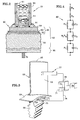
As shown in Figure 2, typical TBC systems 55 for gas turbine engine
components comprise a metallic bondcoat layer 52 overlying a metallic substrate 50, a
thermally insulating ceramic topcoat layer 54 overlying the metallic bondcoat layer
52, and an in situ formed TGO layer 53 disposed between the metallic bondcoat layer
52 and the ceramic topcoat layer 54. The metallic substrate 50 may comprise a
nickel-based superalloy comprising, in weight percent, about 1-25% cobalt, about
1-25% chromium, about 0-8% aluminum, about 0-10% molybdenum, about 0-15%
tungsten, about 0-12% tantalum, about 0-5% titanium, about 0-7% rhenium, about
0-6% ruthenium, about 0-4% niobium, about 0-0.2% carbon, about 0-0.15% boron,
about 0-0.05% yttrium, about 0-1.6% hafnium, with the balance being nickel and
incidental impurities. The metallic bondcoat 52 may comprise a MCrAlY alloy,
where M is Ni, Co, or NiCo, which is applied directly overlying the metallic substrate
50 via electron beam physical vapor deposition (EB-PVD) or any other suitable
method. The thermally insulating ceramic topcoat 54 may comprise yttria stabilized
zirconia, which is applied overlying the metallic bondcoat layer 52 in any suitable
manner.
While this topcoat layer 54 is being deposited, a thermally grown oxide (TGO)
layer 53, such as alumina, forms on the metallic bondcoat layer 52, between the
metallic bondcoat 52 and the ceramic topcoat 54. As time at temperature and number
of cycles increases, this TGO layer 53 grows in thickness, eventually reaching a
critical value, followed by failure of the coating. Defects may also be formed in these
TBC systems during production. Such defects, whether formed during production or
during use, can ultimately lead to failure of the underlying component, which can be
very costly, cumbersome and time consuming to remedy. Ideally, it would be
desirable to be able to estimate the remaining lifetime of a TBC system, so that poor
quality TBCs can be repaired or replaced before damage to the underlying component
occurs. The probes of this invention allow the remaining lifetime of TBC systems to
be estimated, thereby allowing component failures to be prevented. These probes
allow quick and easy non-destructive quality control checks to be made either during
production of the coated component, or whenever direct physical contact between the
probe and a coated component is possible. For example, a coated gas turbine engine
component may not be accessible while on an airplane wing, but the component of
interest may become accessible without having to remove and completely disassemble
the engine.
The probes of this invention may be utilized with any suitable EIS system to
evaluate the coating quality on any coated gas turbine engine component. An
exemplary, non-limiting gas turbine engine component, a blade 60, is shown in Figure
3, having a coated airfoil portion 62 extending outwardly from a platform 64 towards
the blade tip 65, and an uncoated blade root portion 66 extending inwardly from the
platform 64. The coated airfoil portion 62 of blade 60 comprises a thermal barrier
coating system 55 thereon. The exemplary EIS system shown here comprises an
impedance analyzer 72 operatively coupled to the coated component 60 via a pair of
electrical leads 74, 76. Each electrical lead has two ends. One end of each electrical
lead 74, 76 is operatively coupled to the impedance analyzer 72, while the other end
of each lead 74, 76 is operatively coupled to an electrode 75, 77 respectively. In
embodiments, electrical lead 74 is operatively coupled directly to an uncoated portion
of the part (i.e., uncoated blade root portion 66 of blade 60), thereby making the
uncoated portion of the part the working electrode 75. Electrical lead 76 is
operatively coupled to a wetting electrode 77, which contacts a coated portion of the
part (i.e., coated airfoil portion 62 of blade 60). The wetting electrode 77 comprises a
counter electrode 95, and may also comprise a reference electrode 92. When a
continuous electrical path exists between the two electrodes 75, 77, a voltage source
71 may be used to drive a reaction between the counter electrode 95 and the working
electrode 75, and impedance parameters may be measured by the impedance analyzer
72. In embodiments, this voltage source 71 may be part of the impedance analyzer
72. The impedance analyzer 72 may be operatively coupled to a computer 78, which
can display the measured impedance parameters and/or perform analysis thereon to
determine quantitative and/or qualitative properties of the coating based on the
measured parameters.
Various theoretical, empirical or hybrid models may be utilized to determine
coating properties such as layer thickness, the presence, size and quantity of
imperfections (i.e., voids within or between layers of the coating that indicate
separation of the layers or delamination thereof), the degree of degradation of the
coating, the estimated remaining lifetime of the coating, etc.
Figure 4 shows a basic electric circuit model 80 of the TBC system on the gas
turbine engine blade 60 shown in Figures 2 and 3. From one end of the circuit to the
other, the electrolyte solution resistance Rs is shown in series with the resistance of
the electrode RP. This, in turn, is in series with the parallel combination of the topcoat
capacitance CC and the topcoat resistance RC. This, in turn is in series with the
parallel combination of the TGO capacitance CO and the TGO resistance RO
multiplied by a Warburg coefficient WO. This, in turn, is in series with the parallel
combination of the interface capacitance CT and the interface resistance RT of the
interface between the TGO and the bondcoat.
Referring again to Figure 1, an exemplary impedance spectra 10 comprising a
plot 20 of impedance Ω (in Kohm/cm2) versus frequency ω, and a plot 30 of phase
angle versus frequency ω, is shown. The location of the impedance peak 22 is
indicative of the resistance RT of the interface between the TGO and the bondcoat, the
location of the impedance tail 24 is indicative of the resistance Rp of the electrode,
and the location of the impedance transition 26 is indicative of the topcoat resistance
RC and the TGO resistance Ro. The location of the low frequency phase angle peak
32 is indicative of the TGO capacitance CO, the location of the high frequency phase
angle peak 34 is indicative of the topcoat capacitance Cc, and the location of the
phase angle tail 36 is indicative of the interface capacitance CT of the interface
between the TGO and the bondcoat. From this impedance spectra 10, the estimated
remaining lifetime of the TBC can be determined, allowing poor quality TBCs to be
repaired or replaced before damage to the underlying component occurs.
Referring now to Figure 5, one exemplary electrode 77 for use with an
electrochemical impedance system is shown. This particular embodiment of the
electrode 77 is a wetting electrode probe system comprising two electrodes: a working
electrode 75 and a counter electrode 95. This probe 77 comprises a hollow tubular
vessel 90 filled with an electrolyte 91. In this embodiment, the hollow tubular vessel
90 is made of metal so that the hollow tubular vessel 90 itself acts as the counter
electrode 95. This hollow tubular vessel 90 is preferably made of the same metal
material as the base metal alloy of the part (i.e., turbine engine blade 60) being
measured so as to limit polarization effects in the circuit. A check valve 93 is present
at one end of the probe 77 to keep the electrolyte 91 from escaping therefrom, except
when desired. Additionally, o-ring seals 94 or other suitable sealing devices are
disposed at each end of the hollow tubular vessel 90 to keep the electrolyte 91
contained therein. When using this probe 77, the counter electrode 95 i s utilized to
complete the circuit with the working electrode 75, and the reaction between the
counter electrode 95 and the working electrode 75 is driven by a voltage source 71
attached thereto.
Referring now to Figure 6, another exemplary electrode 77 for use with an
electrochemical impedance system is shown. This particular embodiment of the
electrode 77 is also a wetting electrode probe system comprising two electrodes: a
working electrode 75 and a counter electrode 95. In this embodiment, the hollow
tubular vessel 90 is not acting as the counter electrode 95, and therefore, this hollow
tubular vessel 90 may be made of any suitable material, such as for example,
Plexiglas®, which allows the level of electrolyte 91 remaining within the hollow
tubular vessel 90 to be readily assessed. In this embodiment, the counter electrode 95
is disposed within the hollow tubular vessel 90, in operative contact with the
electrolyte 91. This counter electrode 95 preferably comprises the same metal
material as the base metal alloy of the part (i.e., turbine engine blade 60) being
measured so as to limit polarization effects in the circuit. As in the previous
embodiment, this embodiment also comprises a check valve 93 and o-ring seals 94 or
other suitable sealing devices. When using this probe 77, the counter electrode 95 is
utilized to complete the circuit with the working electrode 75, and the reaction
between the counter electrode 95 and the working electrode 75 is driven by a voltage
source 71 attached thereto.
Referring now to Figure 7, another exemplary electrode 77 for use with an
electrochemical impedance system is shown. This particular embodiment of the
electrode 77 is a wetting electrode probe system comprising three electrodes: a
working electrode 75, a counter electrode 95, and a reference electrode 92. As in the
previous embodiment, this hollow tubular vessel 90 is made of metal so that the
hollow tubular vessel 90 itself acts as the counter electrode 95. This hollow tubular
vessel 90 may be made of any suitable metal material, such as for example, a metal
material that is more noble or more active than the base metal alloy of the part (i.e.,
turbine engine blade 60) being measured. This probe 77 also comprises a reference
electrode 92 disposed within the hollow tubular vessel 90 and in operative contact
with the electrolyte 91. This reference electrode 92 may comprise any suitable
electrode, such as for example, a saturated calomel electrode (i.e., Hg/Hg2Cl2) or an
Ag/AgCl electrode. As in the previous embodiment, this probe 77 also comprises a
check valve 93 and o-ring seals 94 or other suitable sealing devices. When using this
probe 77, the counter electrode 95 is utilized to control the potential and complete the
circuit with the working electrode 75, the reaction between the counter electrode 95
and the working electrode 75 is driven by a voltage source 71 attached thereto, and
the reference electrode 92 is utilized to measure the cell potential.
Referring now to Figure 8, another exemplary electrode 77 for use with an
electrochemical impedance system is shown. This particular embodiment of the
electrode 77 is also a wetting electrode probe system comprising three electrodes: a
working electrode 75, a counter electrode 95, and a reference electrode 92. This
probe 77 comprises both a counter electrode 95 and a reference electrode 92 within
the hollow tubular vessel 90 and in operative contact with the electrolyte 91. In this
embodiment, the hollow tubular vessel 90 is not acting as the counter electrode 95,
and therefore, this hollow tubular vessel 90 may be made of any suitable material,
such as for example, Plexiglas®, which allows the level of electrolyte 91 remaining
within the hollow tubular vessel 90 to be readily assessed. As in the previous
embodiment, this reference electrode 92 may comprise any suitable electrode, such as
for example, a saturated calomel electrode (i.e., Hg/Hg2Cl2), or an Ag/AgCl electrode.
This counter electrode 95 may comprise any suitable metal material, such as for
example, platinum or another metal or alloy that is more noble or more active than the
base metal alloy of the part (i.e., turbine engine blade 60) being measured. As in the
previous embodiment, this embodiment also comprises a check valve 93 and o-ring
seals 94 or other suitable sealing devices. One end of this probe 77 also comprises a
holding plate 96 to hold the reference electrode 92 and the counter electrode 95 in
position. O-rings or other suitable sealing devices 97 may be used in conjunction
with the holding plate 96 to keep the electrolyte 91 contained within the hollow
tubular vessel 90. When using this probe 77, the counter electrode 95 is utilized to
control the potential and complete the circuit with the working electrode 75, the
reaction between the counter electrode 95 and the working electrode 75 is driven by a
voltage source 71 attached thereto, and the reference electrode 92 is utilized to
measure the cell potential.
As previously discussed, the working electrode 75 generally comprises the
uncoated portion of the part itself (i.e., the base alloy of the uncoated blade root
portion 66 of the blade 60). The check valve 93 of probe 77 may be positioned on
ceramic topcoat layer 54 of the coated portion 62 of the component 60, as shown in
Figure 2, and when the probe 77 is depressed thereon, the check valve 93 may open
and allow a small amount of electrolyte 91 to flow out therefrom, establishing fluid
communication between the coated component 62 and the electrolyte 91 contained
within the interior of the probe 77. When both electrodes 75, 77 are in position, a
continuous electrical path is established from the uncoated portion 66 of the
component 60 to the impedance analyzer 72 via the working electrode 75 and
electrical lead 74, from the impedance analyzer 72 to the wetting electrode 77 via
electrical lead 76, through the electrolyte 91, and to the thermal barrier coating system
55 on the component 60. Once a continuous electrical path exists between the two
electrodes 75, 77, impedance parameters or other desirable parameters may then be
obtained by the impedance analyzer 72 or other suitable measuring device.
This invention may comprise any suitable electrolyte 91 that does not attack,
destroy or otherwise react with the coating on the coated component being measured,
such as for example, a dilute acid, a mixture of acids, or a salt solution having
sufficient ionic conductivity to allow the EIS measurements to be obtained. Some
suitable, non-limiting electrolytes may comprise one or more of the following
materials: sodium chloride (NaCl), potassium chloride (KCl), sodium sulfate
(NaSO4), and/or potassium hydroxide (KOH).
The amount of electrolyte 91 needed varies depending upon the size of the
hollow tubular vessel 90. However, there should be at least enough electrolyte in the
hollow tubular vessel 90 to sufficiently cover the electrodes therein 92, 95 when the
probe 77 is in use at a variety of angles. Once the hollow tubular vessel 90 is filled
with enough electrolyte 91 to ensure the electrodes disposed therein 92, 95 are in
contact with the electrolyte 91, the probe 77 can then be operatively connected to
commercially available EIS equipment 72 via one or more electrical leads 74, 76.
The EIS equipment 72 may comprises any suitable devices, which in embodiments
may comprise a frequency response analyzer and a data acquisition system. This EIS
equipment may be portable so that assessments of coating quality can be made
quickly and easily in a variety of environments. For example, this invention may
allow quick and easy non-destructive quality control checks to be made either during
production of the coated component, or whenever direct physical contact between a
probe and a coated component is possible, such as in a repair or maintenance
environment.
As described above, this invention provides probes that are specifically
designed to be utilized with EIS systems to assess the quality of TBC systems on gas
turbine engine components such as turbine vanes, turbine blades, combustor panels,
blade outer air seals, turbine exhaust cases, augmentor liners, and any other gas
turbine engine components that may have TBCs thereon. Advantageously, these
probes are easy to use, and allow quality checks to be made in production, repair and
maintenance environments. Therefore, poor quality TBCs can be identified and
repaired or replaced before damage to the underlying component occurs. Many other
embodiments and advantages will be apparent to those skilled in the relevant art.
Various embodiments of this invention have been described in fulfillment of
the various needs that the invention meets. It should be recognized that these
embodiments are merely illustrative of the principles of various embodiments of the
present invention. Numerous modifications and adaptations thereof will be apparent
to those skilled in the art without departing from the spirit and scope of the present
invention. Thus, it is intended that the present invention cover all suitable
modifications and variations as come within the scope of the appended claims and
their equivalents.