EP1600604A1 - Cooler rotor blade and method for cooling a rotor blade - Google Patents
Cooler rotor blade and method for cooling a rotor blade Download PDFInfo
- Publication number
- EP1600604A1 EP1600604A1 EP05253259A EP05253259A EP1600604A1 EP 1600604 A1 EP1600604 A1 EP 1600604A1 EP 05253259 A EP05253259 A EP 05253259A EP 05253259 A EP05253259 A EP 05253259A EP 1600604 A1 EP1600604 A1 EP 1600604A1
- Authority
- EP
- European Patent Office
- Prior art keywords
- passage
- cooling air
- leading edge
- rotor blade
- serpentine
- Prior art date
- Legal status (The legal status is an assumption and is not a legal conclusion. Google has not performed a legal analysis and makes no representation as to the accuracy of the status listed.)
- Granted
Links
Images


Classifications
-
- F—MECHANICAL ENGINEERING; LIGHTING; HEATING; WEAPONS; BLASTING
- F01—MACHINES OR ENGINES IN GENERAL; ENGINE PLANTS IN GENERAL; STEAM ENGINES
- F01D—NON-POSITIVE DISPLACEMENT MACHINES OR ENGINES, e.g. STEAM TURBINES
- F01D5/00—Blades; Blade-carrying members; Heating, heat-insulating, cooling or antivibration means on the blades or the members
- F01D5/12—Blades
- F01D5/14—Form or construction
- F01D5/18—Hollow blades, i.e. blades with cooling or heating channels or cavities; Heating, heat-insulating or cooling means on blades
- F01D5/187—Convection cooling
-
- F—MECHANICAL ENGINEERING; LIGHTING; HEATING; WEAPONS; BLASTING
- F05—INDEXING SCHEMES RELATING TO ENGINES OR PUMPS IN VARIOUS SUBCLASSES OF CLASSES F01-F04
- F05D—INDEXING SCHEME FOR ASPECTS RELATING TO NON-POSITIVE-DISPLACEMENT MACHINES OR ENGINES, GAS-TURBINES OR JET-PROPULSION PLANTS
- F05D2260/00—Function
- F05D2260/20—Heat transfer, e.g. cooling
- F05D2260/221—Improvement of heat transfer
-
- F—MECHANICAL ENGINEERING; LIGHTING; HEATING; WEAPONS; BLASTING
- F05—INDEXING SCHEMES RELATING TO ENGINES OR PUMPS IN VARIOUS SUBCLASSES OF CLASSES F01-F04
- F05D—INDEXING SCHEME FOR ASPECTS RELATING TO NON-POSITIVE-DISPLACEMENT MACHINES OR ENGINES, GAS-TURBINES OR JET-PROPULSION PLANTS
- F05D2260/00—Function
- F05D2260/20—Heat transfer, e.g. cooling
- F05D2260/221—Improvement of heat transfer
- F05D2260/2214—Improvement of heat transfer by increasing the heat transfer surface
- F05D2260/22141—Improvement of heat transfer by increasing the heat transfer surface using fins or ribs
Definitions
- the LE passage 70 is connected to an AE passage 52 that extends to the trailing edge 34 of the airfoil 22, adjacent the tip 30 of the airfoil 22.
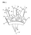
- the airfoil 22 portion of the rotor blade 14 is disposed within the core gas path of the turbine engine.
- the airfoil 22 is subject to high temperature core gas passing by the airfoil 22. Cooling air, that is substantially lower in temperature than the core gas, is fed into the airfoil 22 through the conduits 42,44,46 disposed in the root 20.
- Cooling air traveling through the first conduit 42 passes directly into the one or more LE passages 48 disposed adjacent the leading edge 32, and subsequently into the AE passage 52 adjacent the tip 30 of the airfoil 22.
- the first conduit 42 provides the primary path into these passages 48 for cooling air, although the exact path depends upon the particular LE passage embodiment.
- Cooling air traveling within the second LE passage 58 incurs relatively low pressure losses, and will enter the AE passage 52 at a relatively high pressure and velocity. Because the second LE passage 58 is aft of the first LE passage 56 (and therefore the leading edge 32), the cooling air traveling through the second LE passage 58 is subject to less heat transfer from the leading edge 32. As a result, the cooling air reaches the AE passage 52 typically at a lower temperature than it would be if it were in contact with the leading edge 32. In this embodiment, the AE passage 52 extends across nearly the entire chord of the airfoil 22.
- the cooling air traveling through the LE passage 70 is subject to less heat transfer from the leading edge 32.
- the cooling air reaches the AE passage 52 typically at a lower temperature than it would be if it were in contact with the leading edge 32.
- a portion of the cooling air passing through the AE passage 52 typically exits the AE passage 52 via cooling apertures; e.g., the cooling apertures extending between the tip 30, cavity 60, pressure side wall 36, and/or suction side wall 38.
- cooling apertures e.g., the cooling apertures extending between the tip 30, cavity 60, pressure side wall 36, and/or suction side wall 38.
- cooling air will enter the last radial segment 82 from the AE passage 52 via the one or more apertures 85 extending between the last radial segment 82 and the AE passage 52 (P 2 > P 3 ).
- a cooling air sink 84 e.g., film holes
- the cooling air sink 84 prevents undesirable flow stagnation within the last radial segment 82 of the serpentine passage 78.
- the two opposing flows of cooling air within the serpentine passage 78 will come to rest at a location where the static pressure of each flow equals that of the other.
- the cooling air sink 84 is positioned adjacent that rest location.
- the pressure P 1 of the cooling air entering the serpentine passage 78 prevents the AE passage 52 inflow from traveling completely through the serpentine passage 78 (P 1 > P 2 ).
- Cooling air traveling through the third conduit 46 enters one or more passage(s) 86 disposed between the serpentine passage 78 and the trailing edge 34. All of the cooling air that enters these passages exits via cooling apertures disposed in the walls of the airfoil 22 or along the trailing edge 34.
Landscapes
- Engineering & Computer Science (AREA)
- Mechanical Engineering (AREA)
- General Engineering & Computer Science (AREA)
- Turbine Rotor Nozzle Sealing (AREA)
Abstract
Description
Claims (12)
- A rotor blade (14), comprising:a root (20);a hollow airfoil (22) having a cavity defined by a suction side wall (38), a pressure side wall (36), a leading edge (32), a trailing edge (34), a base (28), and a tip (30);an internal passage configuration (40) disposed within the cavity, which configuration includes a serpentine passage (78) having at least three radial segments (80) connected to one another, an axially extending passage (52) disposed between the tip (30) and the serpentine passage (78), at least one aperture (85) extending between the last radial segment (80) and the axially extending passage (52), and one or more sink apertures (84) disposed within one of the suction side wall (38) or the pressure side wall (36) of the last radial segment (80) of the serpentine passage (78); andat least one conduit (42,44,46) disposed within the root (20) that is operable to permit airflow through the root (20) and into the internal passage configuration (40).
- The rotor blade of claim 1, wherein the internal passage configuration (40) further comprises a leading edge passage (50;58;64;70) disposed between the leading edge (32) and the serpentine passage (78), and the leading edge passage is in fluid communication with the axially extending passage (52).
- The rotor blade of claim 2, wherein the at least one conduit includes a first conduit (42) that is operable to permit airflow through the root (20) and into the leading edge passage (50;58;64;70), and a second conduit (44) that is operable to permit airflow through the root (20) and into the serpentine passage (78).
- The rotor blade of claim 3, wherein the axially extending passage (52) extends between the leading edge passage (50;58;64;70) and the trailing edge (34), and includes an opening that permits cooling air to exit the airfoil (22) at the trailing edge (34).
- The rotor blade of any preceding claim, wherein the one or more sink apertures (84) are disposed in the suction side wall (38).
- The rotor blade of claim 5, wherein the one or more sink apertures (84) are cooperable or formed to produce film cooling.
- The rotor blade of any preceding claim, wherein the serpentine passage (78) is oriented so that the path through the serpentine passage is operable to direct cooling air toward the leading edge (32) of the airfoil (22).
- The rotor blade of any of claims 1 to 6, wherein the serpentine passage (78) is oriented to so that the path through the serpentine passage is operable to direct cooling air toward the trailing edge (34) of the airfoil (22).
- A method for cooling a rotor blade, comprising the steps of:wherein the difference between P2 and P3 causes cooling air to exit the axially extending passage (52) through the at least one aperture (85) extending between the last radial segment (80) and the axially extending passage (52); andproviding a rotor blade as claimed in any preceding claim;providing cooling air into the internal passage configuration (40) at P1;providing cooling air into the axially extending passage (52) at P2; andproviding cooling air into a last radial segment (80) of the serpentine passage (78) at a second segment at P3, wherein P1 > P2 > P3;
wherein the difference between P1 and P2 enables cooling air to enter the serpentine passage (78). - The method of claim 9, wherein the internal passage configuration comprises a leading edge passage (50;58;64;70) disposed between the leading edge (32) and the serpentine passage (78), and the leading edge passage is in fluid communication with the axially extending passage (52), and wherein the cooling air provided within the axially extending passage (52) enters the axially extending passage from the leading edge passage.
- The method of claim 10, wherein cooling air provided within the axially extending passage (52) exits the axially extending passage at the trailing edge (34) of the airfoil.
- The method of claim 9, wherein the one or more sink apertures (84) are positioned at a predicted stagnation point within the last radial segment (80), which stagnation point is a lowest pressure point within the last radial segment (80).
Applications Claiming Priority (2)
| Application Number | Priority Date | Filing Date | Title |
|---|---|---|---|
| US855010 | 2004-05-27 | ||
| US10/855,010 US7186082B2 (en) | 2004-05-27 | 2004-05-27 | Cooled rotor blade and method for cooling a rotor blade |
Publications (2)
| Publication Number | Publication Date |
|---|---|
| EP1600604A1 true EP1600604A1 (en) | 2005-11-30 |
| EP1600604B1 EP1600604B1 (en) | 2011-05-18 |
Family
ID=34979814
Family Applications (1)
| Application Number | Title | Priority Date | Filing Date |
|---|---|---|---|
| EP05253259A Expired - Lifetime EP1600604B1 (en) | 2004-05-27 | 2005-05-27 | Cooler rotor blade and method for cooling a rotor blade |
Country Status (3)
| Country | Link |
|---|---|
| US (1) | US7186082B2 (en) |
| EP (1) | EP1600604B1 (en) |
| JP (1) | JP2005337260A (en) |
Cited By (5)
| Publication number | Priority date | Publication date | Assignee | Title |
|---|---|---|---|---|
| EP2119872A3 (en) * | 2008-05-14 | 2012-08-08 | United Technologies Corporation | Turbine blade internal cooling configuration |
| WO2015181497A1 (en) * | 2014-05-28 | 2015-12-03 | Snecma | Turbine blade with optimised cooling |
| EP2971545A4 (en) * | 2013-03-11 | 2017-02-01 | United Technologies Corporation | Low pressure loss cooled blade |
| CN108920883A (en) * | 2018-08-20 | 2018-11-30 | 南京航空航天大学 | One kind is based on fatigue, the interactive hot-forming die life forecast method of oxidation |
| EP3441570A1 (en) * | 2017-08-08 | 2019-02-13 | United Technologies Corporation | Airfoil having forward flowing serpentine flow |
Families Citing this family (20)
| Publication number | Priority date | Publication date | Assignee | Title |
|---|---|---|---|---|
| DE102007027465A1 (en) * | 2007-06-14 | 2008-12-18 | Rolls-Royce Deutschland Ltd & Co Kg | Gas turbine blade with modular construction |
| US7950903B1 (en) * | 2007-12-21 | 2011-05-31 | Florida Turbine Technologies, Inc. | Turbine blade with dual serpentine cooling |
| US8016563B1 (en) * | 2007-12-21 | 2011-09-13 | Florida Turbine Technologies, Inc. | Turbine blade with tip turn cooling |
| US8087891B1 (en) * | 2008-01-23 | 2012-01-03 | Florida Turbine Technologies, Inc. | Turbine blade with tip region cooling |
| US8177507B2 (en) * | 2008-05-14 | 2012-05-15 | United Technologies Corporation | Triangular serpentine cooling channels |
| US8083486B1 (en) * | 2009-05-15 | 2011-12-27 | Florida Turbine Technologies, Inc. | Turbine blade with cooling flow modulation |
| US8353669B2 (en) * | 2009-08-18 | 2013-01-15 | United Technologies Corporation | Turbine vane platform leading edge cooling holes |
| US8764379B2 (en) * | 2010-02-25 | 2014-07-01 | General Electric Company | Turbine blade with shielded tip coolant supply passageway |
| US8540481B2 (en) * | 2010-04-13 | 2013-09-24 | Rolls-Royce Corporation | Rotor blade assembly |
| US8613597B1 (en) * | 2011-01-17 | 2013-12-24 | Florida Turbine Technologies, Inc. | Turbine blade with trailing edge cooling |
| GB201121531D0 (en) * | 2011-12-15 | 2012-01-25 | Rolls Royce Plc | Aerofoil blade or vane |
| US10774655B2 (en) * | 2014-04-04 | 2020-09-15 | Raytheon Technologies Corporation | Gas turbine engine component with flow separating rib |
| US9810072B2 (en) * | 2014-05-28 | 2017-11-07 | General Electric Company | Rotor blade cooling |
| US10689988B2 (en) | 2014-06-12 | 2020-06-23 | Raytheon Technologies Corporation | Disk lug impingement for gas turbine engine airfoil |
| CN107109949A (en) * | 2014-11-11 | 2017-08-29 | 西门子公司 | Turbo blade with axial leaf top cooling circuit |
| US20180161853A1 (en) * | 2016-12-13 | 2018-06-14 | General Electric Company | Integrated casting core-shell structure with floating tip plenum |
| US10718219B2 (en) * | 2017-12-13 | 2020-07-21 | Solar Turbines Incorporated | Turbine blade cooling system with tip diffuser |
| US12392246B2 (en) | 2023-06-12 | 2025-08-19 | Rtx Corporation | Airfoil cooling circuit |
| US12553350B2 (en) * | 2024-02-20 | 2026-02-17 | Rtx Corporation | Combined tip flag blade core |
| US20260022639A1 (en) | 2024-05-16 | 2026-01-22 | Solar Turbines Incorporated | Turbine blade cooling features |
Citations (4)
| Publication number | Priority date | Publication date | Assignee | Title |
|---|---|---|---|---|
| EP0302810A2 (en) * | 1987-08-06 | 1989-02-08 | United Technologies Corporation | Tripple pass cooled airfoil |
| EP0340149A1 (en) * | 1988-04-25 | 1989-11-02 | United Technologies Corporation | Dirt removal means for air cooled blades |
| US5403159A (en) * | 1992-11-30 | 1995-04-04 | United Technoligies Corporation | Coolable airfoil structure |
| EP1065343A2 (en) * | 1999-06-29 | 2001-01-03 | General Electric Company | Airfoil leading edge cooling |
Family Cites Families (5)
| Publication number | Priority date | Publication date | Assignee | Title |
|---|---|---|---|---|
| US4474532A (en) * | 1981-12-28 | 1984-10-02 | United Technologies Corporation | Coolable airfoil for a rotary machine |
| US4753575A (en) * | 1987-08-06 | 1988-06-28 | United Technologies Corporation | Airfoil with nested cooling channels |
| US5931638A (en) * | 1997-08-07 | 1999-08-03 | United Technologies Corporation | Turbomachinery airfoil with optimized heat transfer |
| US5902093A (en) * | 1997-08-22 | 1999-05-11 | General Electric Company | Crack arresting rotor blade |
| US6595748B2 (en) * | 2001-08-02 | 2003-07-22 | General Electric Company | Trichannel airfoil leading edge cooling |
-
2004
- 2004-05-27 US US10/855,010 patent/US7186082B2/en not_active Expired - Lifetime
-
2005
- 2005-05-27 JP JP2005154981A patent/JP2005337260A/en active Pending
- 2005-05-27 EP EP05253259A patent/EP1600604B1/en not_active Expired - Lifetime
Patent Citations (4)
| Publication number | Priority date | Publication date | Assignee | Title |
|---|---|---|---|---|
| EP0302810A2 (en) * | 1987-08-06 | 1989-02-08 | United Technologies Corporation | Tripple pass cooled airfoil |
| EP0340149A1 (en) * | 1988-04-25 | 1989-11-02 | United Technologies Corporation | Dirt removal means for air cooled blades |
| US5403159A (en) * | 1992-11-30 | 1995-04-04 | United Technoligies Corporation | Coolable airfoil structure |
| EP1065343A2 (en) * | 1999-06-29 | 2001-01-03 | General Electric Company | Airfoil leading edge cooling |
Cited By (10)
| Publication number | Priority date | Publication date | Assignee | Title |
|---|---|---|---|---|
| EP2119872A3 (en) * | 2008-05-14 | 2012-08-08 | United Technologies Corporation | Turbine blade internal cooling configuration |
| EP2971545A4 (en) * | 2013-03-11 | 2017-02-01 | United Technologies Corporation | Low pressure loss cooled blade |
| US9932837B2 (en) | 2013-03-11 | 2018-04-03 | United Technologies Corporation | Low pressure loss cooled blade |
| WO2015181497A1 (en) * | 2014-05-28 | 2015-12-03 | Snecma | Turbine blade with optimised cooling |
| FR3021697A1 (en) * | 2014-05-28 | 2015-12-04 | Snecma | OPTIMIZED COOLING TURBINE BLADE |
| RU2697211C2 (en) * | 2014-05-28 | 2019-08-13 | Сафран Эркрафт Энджинз | Turbine blade with optimized cooling |
| US10689985B2 (en) | 2014-05-28 | 2020-06-23 | Safran Aircraft Engines | Turbine blade with optimised cooling |
| EP3441570A1 (en) * | 2017-08-08 | 2019-02-13 | United Technologies Corporation | Airfoil having forward flowing serpentine flow |
| US10794195B2 (en) | 2017-08-08 | 2020-10-06 | Raytheon Technologies Corporation | Airfoil having forward flowing serpentine flow |
| CN108920883A (en) * | 2018-08-20 | 2018-11-30 | 南京航空航天大学 | One kind is based on fatigue, the interactive hot-forming die life forecast method of oxidation |
Also Published As
| Publication number | Publication date |
|---|---|
| US20050265836A1 (en) | 2005-12-01 |
| EP1600604B1 (en) | 2011-05-18 |
| US7186082B2 (en) | 2007-03-06 |
| JP2005337260A (en) | 2005-12-08 |
Similar Documents
| Publication | Publication Date | Title |
|---|---|---|
| US7186082B2 (en) | Cooled rotor blade and method for cooling a rotor blade | |
| US7665968B2 (en) | Cooled rotor blade | |
| EP1444418B1 (en) | Internal cooled gas turbine vane or blade | |
| JP3053174B2 (en) | Wing for use in turbomachine and method of manufacturing the same | |
| US7217095B2 (en) | Heat transferring cooling features for an airfoil | |
| US5813836A (en) | Turbine blade | |
| US5215431A (en) | Cooled turbine guide vane | |
| JP3367697B2 (en) | Blades for turbines | |
| EP2676000B1 (en) | Integrated axial and tangential serpentine cooling circuit in a turbine airfoil | |
| US7195448B2 (en) | Cooled rotor blade | |
| EP1605136B1 (en) | Cooled rotor blade | |
| US8366393B2 (en) | Rotor blade | |
| EP2917494B1 (en) | Blade for a turbomachine | |
| EP3064712B1 (en) | Airfoil comprising baffle insert | |
| EP1013881B1 (en) | Coolable airfoils | |
| US6102658A (en) | Trailing edge cooling apparatus for a gas turbine airfoil | |
| EP1605138B1 (en) | Cooled rotor blade with leading edge impingement cooling | |
| EP2752554A1 (en) | Blade for a turbomachine | |
| KR20040064649A (en) | Trailing edge cooling | |
| JPS58119902A (en) | Forced cooling type fluid directional blade-shaped member for combustion turbine |
Legal Events
| Date | Code | Title | Description |
|---|---|---|---|
| PUAI | Public reference made under article 153(3) epc to a published international application that has entered the european phase |
Free format text: ORIGINAL CODE: 0009012 |
|
| AK | Designated contracting states |
Kind code of ref document: A1 Designated state(s): AT BE BG CH CY CZ DE DK EE ES FI FR GB GR HU IE IS IT LI LT LU MC NL PL PT RO SE SI SK TR |
|
| AX | Request for extension of the european patent |
Extension state: AL BA HR LV MK YU |
|
| 17P | Request for examination filed |
Effective date: 20051216 |
|
| AKX | Designation fees paid |
Designated state(s): DE FR GB IT |
|
| GRAP | Despatch of communication of intention to grant a patent |
Free format text: ORIGINAL CODE: EPIDOSNIGR1 |
|
| GRAS | Grant fee paid |
Free format text: ORIGINAL CODE: EPIDOSNIGR3 |
|
| GRAA | (expected) grant |
Free format text: ORIGINAL CODE: 0009210 |
|
| REG | Reference to a national code |
Ref country code: DE Ref legal event code: R081 Ref document number: 602005028066 Country of ref document: DE Owner name: UNITED TECHNOLOGIES CORP. (N.D.GES.D. STAATES , US Free format text: FORMER OWNER: UNITED TECHNOLOGIES CORP. (N.D.GES.D. STAATES DELAWARE), HARTFORD, CONN., US |
|
| AK | Designated contracting states |
Kind code of ref document: B1 Designated state(s): DE FR GB IT |
|
| REG | Reference to a national code |
Ref country code: GB Ref legal event code: FG4D |
|
| REG | Reference to a national code |
Ref country code: DE Ref legal event code: R096 Ref document number: 602005028066 Country of ref document: DE Effective date: 20110630 |
|
| PLBE | No opposition filed within time limit |
Free format text: ORIGINAL CODE: 0009261 |
|
| STAA | Information on the status of an ep patent application or granted ep patent |
Free format text: STATUS: NO OPPOSITION FILED WITHIN TIME LIMIT |
|
| 26N | No opposition filed |
Effective date: 20120221 |
|
| PG25 | Lapsed in a contracting state [announced via postgrant information from national office to epo] |
Ref country code: FR Free format text: LAPSE BECAUSE OF NON-PAYMENT OF DUE FEES Effective date: 20110718 |
|
| REG | Reference to a national code |
Ref country code: FR Ref legal event code: ST Effective date: 20120330 |
|
| PG25 | Lapsed in a contracting state [announced via postgrant information from national office to epo] |
Ref country code: IT Free format text: LAPSE BECAUSE OF FAILURE TO SUBMIT A TRANSLATION OF THE DESCRIPTION OR TO PAY THE FEE WITHIN THE PRESCRIBED TIME-LIMIT Effective date: 20110518 |
|
| REG | Reference to a national code |
Ref country code: DE Ref legal event code: R097 Ref document number: 602005028066 Country of ref document: DE Effective date: 20120221 |
|
| REG | Reference to a national code |
Ref country code: DE Ref legal event code: R082 Ref document number: 602005028066 Country of ref document: DE Representative=s name: SCHMITT-NILSON SCHRAUD WAIBEL WOHLFROM PATENTA, DE |
|
| REG | Reference to a national code |
Ref country code: DE Ref legal event code: R082 Ref document number: 602005028066 Country of ref document: DE Representative=s name: SCHMITT-NILSON SCHRAUD WAIBEL WOHLFROM PATENTA, DE Ref country code: DE Ref legal event code: R081 Ref document number: 602005028066 Country of ref document: DE Owner name: UNITED TECHNOLOGIES CORP. (N.D.GES.D. STAATES , US Free format text: FORMER OWNER: UNITED TECHNOLOGIES CORPORATION, HARTFORD, CONN., US |
|
| PGFP | Annual fee paid to national office [announced via postgrant information from national office to epo] |
Ref country code: DE Payment date: 20190418 Year of fee payment: 15 |
|
| REG | Reference to a national code |
Ref country code: DE Ref legal event code: R119 Ref document number: 602005028066 Country of ref document: DE |
|
| PG25 | Lapsed in a contracting state [announced via postgrant information from national office to epo] |
Ref country code: DE Free format text: LAPSE BECAUSE OF NON-PAYMENT OF DUE FEES Effective date: 20201201 |
|
| PGFP | Annual fee paid to national office [announced via postgrant information from national office to epo] |
Ref country code: GB Payment date: 20240418 Year of fee payment: 20 |
|
| REG | Reference to a national code |
Ref country code: GB Ref legal event code: PE20 Expiry date: 20250526 |
|
| PG25 | Lapsed in a contracting state [announced via postgrant information from national office to epo] |
Ref country code: GB Free format text: LAPSE BECAUSE OF EXPIRATION OF PROTECTION Effective date: 20250526 |