EP1600598A2 - Tube motor for use in motor-driven shutter or motor-driven blind - Google Patents
Tube motor for use in motor-driven shutter or motor-driven blind Download PDFInfo
- Publication number
- EP1600598A2 EP1600598A2 EP05003375A EP05003375A EP1600598A2 EP 1600598 A2 EP1600598 A2 EP 1600598A2 EP 05003375 A EP05003375 A EP 05003375A EP 05003375 A EP05003375 A EP 05003375A EP 1600598 A2 EP1600598 A2 EP 1600598A2
- Authority
- EP
- European Patent Office
- Prior art keywords
- motor
- pipe
- components
- tube
- shutter
- Prior art date
- Legal status (The legal status is an assumption and is not a legal conclusion. Google has not performed a legal analysis and makes no representation as to the accuracy of the status listed.)
- Withdrawn
Links
- 230000010354 integration Effects 0.000 claims description 4
- 238000004804 winding Methods 0.000 description 19
- 238000000034 method Methods 0.000 description 6
- 230000000694 effects Effects 0.000 description 4
- 238000009434 installation Methods 0.000 description 4
- 239000003990 capacitor Substances 0.000 description 3
- 239000003638 chemical reducing agent Substances 0.000 description 3
- 239000002184 metal Substances 0.000 description 2
- 210000002105 tongue Anatomy 0.000 description 2
- 239000011230 binding agent Substances 0.000 description 1
- 238000007689 inspection Methods 0.000 description 1
Images


Classifications
-
- E—FIXED CONSTRUCTIONS
- E06—DOORS, WINDOWS, SHUTTERS, OR ROLLER BLINDS IN GENERAL; LADDERS
- E06B—FIXED OR MOVABLE CLOSURES FOR OPENINGS IN BUILDINGS, VEHICLES, FENCES OR LIKE ENCLOSURES IN GENERAL, e.g. DOORS, WINDOWS, BLINDS, GATES
- E06B9/00—Screening or protective devices for wall or similar openings, with or without operating or securing mechanisms; Closures of similar construction
- E06B9/56—Operating, guiding or securing devices or arrangements for roll-type closures; Spring drums; Tape drums; Counterweighting arrangements therefor
- E06B9/68—Operating devices or mechanisms, e.g. with electric drive
- E06B9/72—Operating devices or mechanisms, e.g. with electric drive comprising an electric motor positioned inside the roller
-
- H—ELECTRICITY
- H02—GENERATION; CONVERSION OR DISTRIBUTION OF ELECTRIC POWER
- H02K—DYNAMO-ELECTRIC MACHINES
- H02K11/00—Structural association of dynamo-electric machines with electric components or with devices for shielding, monitoring or protection
- H02K11/30—Structural association with control circuits or drive circuits
- H02K11/33—Drive circuits, e.g. power electronics
-
- H—ELECTRICITY
- H02—GENERATION; CONVERSION OR DISTRIBUTION OF ELECTRIC POWER
- H02K—DYNAMO-ELECTRIC MACHINES
- H02K5/00—Casings; Enclosures; Supports
- H02K5/04—Casings or enclosures characterised by the shape, form or construction thereof
-
- H—ELECTRICITY
- H02—GENERATION; CONVERSION OR DISTRIBUTION OF ELECTRIC POWER
- H02K—DYNAMO-ELECTRIC MACHINES
- H02K7/00—Arrangements for handling mechanical energy structurally associated with dynamo-electric machines, e.g. structural association with mechanical driving motors or auxiliary dynamo-electric machines
- H02K7/14—Structural association with mechanical loads, e.g. with hand-held machine tools or fans
-
- H—ELECTRICITY
- H02—GENERATION; CONVERSION OR DISTRIBUTION OF ELECTRIC POWER
- H02K—DYNAMO-ELECTRIC MACHINES
- H02K2207/00—Specific aspects not provided for in the other groups of this subclass relating to arrangements for handling mechanical energy
- H02K2207/03—Tubular motors, i.e. rotary motors mounted inside a tube, e.g. for blinds
-
- H—ELECTRICITY
- H02—GENERATION; CONVERSION OR DISTRIBUTION OF ELECTRIC POWER
- H02K—DYNAMO-ELECTRIC MACHINES
- H02K5/00—Casings; Enclosures; Supports
- H02K5/04—Casings or enclosures characterised by the shape, form or construction thereof
- H02K5/22—Auxiliary parts of casings not covered by groups H02K5/06-H02K5/20, e.g. shaped to form connection boxes or terminal boxes
- H02K5/225—Terminal boxes or connection arrangements
Definitions
- the present invention relates to a tube motor for use in a motor-driven shutter or motor-driven blind, and more particularly to a tube motor that allows easy assembly and disassembly thereof and easy replacement of components thereof.
- a tube motor for driving a rotary tube core of a motor-driven shutter or motor-driven blind is configured such that a motor body and other components are accommodated in a pipe that serves as a shell of the tube motor.
- the motor body includes a plurality of components that are arranged axially. The components are sequentially press-fitted into the pipe,and connected axially while being aligned with each other (arranged straight), whereby the motor body is assembled. Accordingly, the pipe is manufactured in the form of a single-piece component.
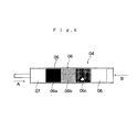
- FIG. 6 shows such a conventional tube motor disclosed in, for example, Japanese Patent Application Laid-Open ( kokai ) No. H09-088458.
- reference numeral 04 denotes a tube motor.
- a pipe 05 which serves as a shell of the tube motor 04, assumes the form of an elongated single-piece component.
- the pipe 05 accommodates a motor body 06; a gear unit 07, which serves as a speed reducer; and a motor unit 08, which includes a capacitor and components for limit switches.
- the motor body 06 includes a plurality of motor body components, usually three motor body components 06a, 06b, and 06c, which can be axially disassembled.
- the motor body components 06a and 06c are bracket structures disposed on opposite sides of the motor body 06
- the motor body components 06a and 06c sandwich and fixedly hold a stator that partially constitutes the motor body component 06b, and rotatably support a rotary shaft of a rotor that partially constitutes the motor body component 06b.
- the motor body components 06a to 06c, the gear unit 07, and the motor unit 08 are accommodated and assembled in the pipe 05 in the following manner.
- the gear unit 07 is inserted into the left end (as viewed in FIG. 6) of the pipe 05 in the direction of an arrow A and fixed therein.
- the motor body component 06a is press-fitted into the pipe 05 in the direction of an arrow B and fixedly connected to the gear unit 07.
- the motor body component 06b is press-fitted into the pipe05 in the direction of the arrow B and fixedly connected to the motor body component 06a.
- the motor body component 06c is press-fitted into the pipe 05 in the direction of the arrow B and fixedly connected to the motor body component 06b.
- the motor unit 08 is inserted into the right end (as viewed in FIG. 6) of the pipe 05 in the direction of arrow B and fixed therein.
- the motor body components 06a to 06c are aligned with each other (arranged straight) and mutually connected, whereby the motor body 06 is completed.
- the assembly work involves the following problems: since the condition of the assembled components in the pipe 05 is not easy to inspect, the assembly work is difficult; and when any one of the components is to be replaced, all of the components must be removed from inside the pipe 05.
- An object of the present invention is to solve the above-mentioned problems in a conventional tube motor for use in a motor-driven shutter or motor-driven blind and to provide a tube motor for use in a motor-driven shutter or motor-driven blind that allows easy inspection of the assembled condition of motor components in a pipe to thereby facilitate assembly work, and allows easy replacement of the motor components.
- the present invention provides a tube motor for use in a motor-driven shutter or motor-driven blind comprising a pipe that serves as a shell of the tube motor adapted to drive a rotary tube core of the motor-driven shutter or motor-driven blind.
- the pipe is composed of two half pieces assembled together.
- the above-mentioned configuration of the present invention allows the following procedure for installing motor body components, a gear unit, a motor unit, and other components in the pipe.
- the components are placed and assembled in one half piece of the pipe.
- the other half piece of the pipe is placed on the former half piece so as to cover the accommodated components.
- the two half pieces are joined together.
- the components can be assembled in the pipe while the condition of assembling the components is observed, the work of assembling the components is remarkably facilitated. In the event of a need to replace any one of the components, the replacement work is remarkably facilitated, because the pipe can be disassembled to the half pieces so as to remove only a component to be replaced.
- a motor body accommodated in the pipe comprises a plurality of components which can be axially disassembled, and the components are axially connected for integration in an axially aligned condition before being accommodated in the pipe.
- the plurality of components of the motor body are axially connected for integration in an axially aligned condition before being accommodated in the pipe, there is no need to follow the conventional assembly procedure in which the components of the motor body are sequentially press-fitted into the pipe and assembled while being aligned with each other. This further encourages use of the pipe composed of two half pieces assembled together, and further enhances the above-described effect attained through use of the pipe composed of two half pieces assembled together.
- a motor-driven shutter to which a tube motor of the present embodiment is applied is configured as briefly described below.
- FIG. 1 schematically shows an upper frame portion of the motor-driven shutter as viewed after removing a shutter body (not shown) from a shutter-winding drum 3.
- the shutter-winding drum 3 is rotatably supported between right and left vertical frames 2r and 2l of a frame 2.
- the frame 2 serves as a cover of the motor-driven shutter 1.
- the shutter-winding drum 3 is rotatably driven by a tube motor 4. Since the shutter-winding drum 3 serves as a rotary, tubular core for the shutter body, the shutter-winding drum 3 is also called a rotary tube core.
- the tube motor 4 has an appearance of an elongated circular cylinder.
- the tube motor 4 is fixedly attached to the right vertical frame 2r in such a manner that a right end portion (as viewed in FIG. 1) thereof projects from the shutter-winding drum 3 while the remaining portion thereof is accommodated in the shutter-winding drum 3.
- An output shaft 9, which projects from the left end (as viewed in FIG. 1) of the tube motor 4, is located within the shutter-winding drum 3 and connected to a rotation-transmitting member 10, which is united to the shutter-winding drum 3.
- Rotational output of the tube motor 4 is transmitted to the shutter-winding drum 3 via the rotation-transmitting member 10. Accordingly, the tube motor 4 and the shutter-winding drum 3 can rotate relative to each other.
- a drum rotary-shaft 11 is provided in a projecting condition on the left end face (as viewed in FIG. 1) of the shutter-winding drum 3.
- the drum rotary-shaft 11 is supported by a bearing member (not shown) provided on the left vertical frame 21.
- an internal gear 12 is provided at a right end portion of the shutter-winding drum 3 to be located between the shutter-winding drum 3 and the tube motor 4.
- the shutter-winding drum 3 rotates in a sliding relation with the tube motor 4 via the internal gear 12.
- the shutter-winding drum 3 Upon reception of rotational output of the tube motor 4 via the rotation-transmitting member 10, the shutter-winding drum 3 rotates while being supported as follows: the drum rotary-shaft 11 is supported by the bearing member provided on the left vertical frame 21, and a right end portion of the shutter-winding drum 3 located opposite the drum rotary-shaft 11 is supported by the tube motor 4 via the internal gear 12. As the shutter-winding drum 3 rotates forward or in reverse, the shutter is fed downward or wound up.
- a fixing member 13 fixedly attached to a right end portion (as viewed in FIG. 1) of the tube motor 4 is fixed on the right vertical frame 2r by means of, for example, screws, thereby fixing the tube motor 4 in place.
- the fixing member 13 accommodates components for limit switches; and a cable 14 for supplying power to the tube motor 4 extends therefrom.
- the tube motor 4 is configured such that an elongated pipe 5 accommodates a motor body 6, a gear unit 7, and a motor unit 8 (FIGS. 1 to 3).
- the pipe 5 serves as a shell of the tube motor 4;
- the gear unit 7 serves as a speed reducer; and
- the motor unit 8 includes a capacitor and components for limit switches.
- the motor body 6 includes a plurality of motor body components, usually three motor body components 6a, 6b, and 6c, which can be axially disassembled.
- the motor body components 6a and 6c are bracket structures disposed on opposite sides of the motor body 6.
- the motor body components 6a and 6c sandwich and fixedly hold a stator that partially constitutes the motor body component 6b, and rotatably support a rotary shaft of a rotor that partially constitutes the motor body component 6b.
- the motor body components 6a to 6c are of the same diameter and assume a circular cross section.
- the motor body components 6a to 6c are unitarily connected beforehand in an axially aligned condition by means of a binder without use of screws, thereby being assembled beforehand into the motor body 6.
- the motor body 6 is small-sized and robust; has a simple structure; is easy to assemble; and allows the shutter-winding drum 3 to have a reduced inside diameter.
- the motor body 6 having such a structure is described in detail in Japanese Patent Application Laid-Open ( kokai ) No. 2002-186213 filed by the applicant of the present invention.
- the motor body 6 used in the present embodiment is not limited to the type having the above-described structure.
- the motor body 6 may be of such a type that the motor body components 6a to 6c are assembled into the motor body 6 after being accommodated in the pipe 5.
- the pipe 5 of the tube motor 4 of the present embodiment assumes the form of an assembly of two axially split half pieces 5a and 5b.
- the pipe 5 is disassembled into the two half pieces 5a and 5b. Then, for example, the gear unit 7, the motor body 6, and the motor unit 8 are sequentially, from left to right in FIG. 2, placed in the half piece 5a. Subsequently, a predetermined joining and connection work is performed. Since the pipe 5 is disassembled into the two half pieces 5a and 5b, the connecting work can be carried out while the conditions of the components are observed, and is thus facilitated.
- the motor body components 6a to 6c are placed in this order in the half piece 5a; aligned with each other (arranged straight) while the conditions of the components are observed; and connected in a required condition.
- the work of connection in the half piece 5a becomes unnecessary in the case where, before installation in the pipe 5, the motor body components 6a to 6c are axially connected in an aligned condition to thereby be assembled into the motor body 6.
- FIG. 5A tongues 15a project from corresponding abutment portions of the half pieces 5a and 5b, and the tongues 15a are joined together by use of screws 15b;
- FIG. 5B a metal plate 15c is placed on the boundary between the two half pieces 5a and 5b, and opposite end portions of the metal plate 15c are screwed on the corresponding half pieces 5a and 5b by use of the corresponding screws 15b;
- FIG. 5C abutment portions of the half pieces 5a and 5b are caused to overlap each other, and the overlapping portions are joined together by use of the screws 15b.
- the tube motor 4 of the present embodiment is configured as described above, the tube motor 4 yields the effects described below.
- a two-piece structure composed of the two half pieces 5a and 5b is applied to the pipe 5, which serves as a shell of the tube motor 4 for use in the motor-driven shutter 1, the following procedure can be employed for installing, in the pipe 5, the motor body components 6a to 6c, the gear unit 7, the motor unit 8, and other components.
- the components are placed and assembled in the half piece 5a or 5b of the pipe 5.
- the other half piece 5a or 5b is placed on the former half piece 5a or 5b so as to cover the accommodated components.
- the two half pieces 5a and 5b are joined together.
- the components can be assembled in the pipe 5 while the condition of assembling the components is observed, the work of assembling the components is remarkably facilitated. Moreover, in the event of a need to replace of any one of the components, the replacement work is remarkably facilitated, because the pipe 5 can be disassembled to the half pieces 5a and 5b so as to remove only a component to be replaced.
- the motor body 6 accommodated in the pipe 5 is composed of the plurality of motor body components 6a to 6c which can be axially disassembled, and the motor body components 6a to 6c are axially connected for integration in an axially aligned condition before being accommodated in the pipe 5, there is no need to follow the conventional assembly procedure in which the motor body components 6a to 6c of the motor body 6 are sequentially press-fitted into the pipe 5 and assembled while being aligned with each other. This further encourages use of the pipe 5 composed of the two half pieces 5a and 5b assembled together, and further enhances the above-described effect attained through use of the pipe 5 composed of the two half pieces 5a and 5b assembled together.
- the tube motor 4 may be applied to a motor-driven blind instead of the motor-driven shutter 1. Even in this case, the above-mentioned effects are similarly yielded.
Landscapes
- Engineering & Computer Science (AREA)
- Power Engineering (AREA)
- Structural Engineering (AREA)
- Architecture (AREA)
- Civil Engineering (AREA)
- Microelectronics & Electronic Packaging (AREA)
- Operating, Guiding And Securing Of Roll- Type Closing Members (AREA)
- Connection Of Motors, Electrical Generators, Mechanical Devices, And The Like (AREA)
Abstract
A pipe serving as a shell of a tube motor adapted to drive a rotary tube core of a motor-driven shutter or motor -driven blind is composed of two half pieces assembled together. <IMAGE>
Description
The present invention relates to a tube motor for use
in a motor-driven shutter or motor-driven blind, and more
particularly to a tube motor that allows easy assembly and
disassembly thereof and easy replacement of components
thereof.
Conventionally, a tube motor for driving a rotary tube
core of a motor-driven shutter or motor-driven blind is
configured such that a motor body and other components are
accommodated in a pipe that serves as a shell of the tube
motor. The motor body includes a plurality of components
that are arranged axially. The components are sequentially
press-fitted into the pipe,and connected axially while
being aligned with each other (arranged straight), whereby
the motor body is assembled. Accordingly, the pipe is
manufactured in the form of a single-piece component.
FIG. 6 shows such a conventional tube motor disclosed
in, for example, Japanese Patent Application Laid-Open
(kokai) No. H09-088458. In FIG. 6, reference numeral 04
denotes a tube motor. A pipe 05, which serves as a shell of
the tube motor 04, assumes the form of an elongated single-piece
component. The pipe 05 accommodates a motor body 06;a
gear unit 07, which serves as a speed reducer; and a motor
unit 08, which includes a capacitor and components for limit
switches. The motor body 06 includes a plurality of motor
body components, usually three motor body components 06a,
06b, and 06c, which can be axially disassembled.
The motor body components 06a and 06c are bracket
structures disposed on opposite sides of the motor body 06
The motor body components 06a and 06c sandwich and fixedly
hold a stator that partially constitutes the motor body
component 06b, and rotatably support a rotary shaft of a
rotor that partially constitutes the motor body component 06b.
Conventionally, the motor body components 06a to 06c,
the gear unit 07, and the motor unit 08 are accommodated
and assembled in the pipe 05 in the following manner.
First, the gear unit 07 is inserted into the left end
(as viewed in FIG. 6) of the pipe 05 in the direction of an
arrow A and fixed therein. Next, the motor body component
06a is press-fitted into the pipe 05 in the direction of an
arrow B and fixedly connected to the gear unit 07. Then, the
motor body component 06b is press-fitted into the pipe05 in
the direction of the arrow B and fixedly connected to the
motor body component 06a. Subsequently, the motor body
component 06c is press-fitted into the pipe 05 in the
direction of the arrow B and fixedly connected to the motor
body component 06b. Finally, the motor unit 08 is inserted
into the right end (as viewed in FIG. 6) of the pipe 05 in
the direction of arrow B and fixed therein.
Being press-fitted into the pipe 05 as mentioned above,
the motor body components 06a to 06c are aligned with each
other (arranged straight) and mutually connected, whereby the
motor body 06 is completed.
However, in assembling the conventional tube motor 04,
the motor body components 06a to 06c, the gear unit 07, and
the motor unit 08 are inserted into the pipe 05, which
assumes the form of a single-piece component. Thus, the
assembly work involves the following problems: since the
condition of the assembled components in the pipe 05 is not
easy to inspect, the assembly work is difficult; and when any
one of the components is to be replaced, all of the
components must be removed from inside the pipe 05.
An object of the present invention is to solve the
above-mentioned problems ina conventional tube motor for use
in a motor-driven shutter or motor-driven blind and to
provide a tube motor for use in a motor-driven shutter or
motor-driven blind that allows easy inspection of the
assembled condition of motor components in a pipe to thereby
facilitate assembly work, and allows easy replacement of the
motor components.
To achieve the above object, the present invention
provides a tube motor for use in a motor-driven shutter or
motor-driven blind comprising a pipe that serves as a shell
of the tube motor adapted to drive a rotary tube core of the
motor-driven shutter or motor-driven blind. In the tube
motor, the pipe is composed of two half pieces assembled
together.
The above-mentioned configuration of the present
invention allows the following procedure for installing motor
body components, a gear unit, a motor unit, and other
components in the pipe. The components are placed and
assembled in one half piece of the pipe. Next, the other
half piece of the pipe is placed on the former half piece so
as to cover the accommodated components. Then, the two half
pieces are joined together.
Since the components can be assembled in the pipe while
the condition of assembling the components is observed, the
work of assembling the components is remarkably facilitated.
In the event of a need to replace any one of the components,
the replacement work is remarkably facilitated, because the
pipe can be disassembled to the half pieces so as to remove
only a component to be replaced.
In the present invention, preferably, a motor body
accommodated in the pipe comprises a plurality of components
which can be axially disassembled, and the components are
axially connected for integration in an axially aligned
condition before being accommodated in the pipe.
Since the plurality of components of the motor body are
axially connected for integration in an axially aligned
condition before being accommodated in the pipe, there is no
need to follow the conventional assembly procedure in which
the components of the motor body are sequentially press-fitted
into the pipe and assembled while being aligned with
each other. This further encourages use of the pipe composed
of two half pieces assembled together, and further enhances
the above-described effect attained through use of the pipe
composed of two half pieces assembled together.
An embodiment of the present invention will next be
described in detail with reference to the drawings.
A motor-driven shutter to which a tube motor of the
present embodiment is applied is configured as briefly
described below.
In FIG. 1, reference numeral 1 denotes the motor-driven
shutter. FIG. 1 schematically shows an upper frame portion
of the motor-driven shutter as viewed after removing a
shutter body (not shown) from a shutter-winding drum 3. The
shutter-winding drum 3 is rotatably supported between right
and left vertical frames 2r and 2l of a frame 2. The frame 2
serves as a cover of the motor-driven shutter 1. The
shutter-winding drum 3 is rotatably driven by a tube motor 4.
Since the shutter-winding drum 3 serves as a rotary, tubular
core for the shutter body, the shutter-winding drum 3 is also
called a rotary tube core.
The tube motor 4 has an appearance of an elongated
circular cylinder. The tube motor 4 is fixedly attached to
the right vertical frame 2r in such a manner that a right end
portion (as viewed in FIG. 1) thereof projects from the
shutter-winding drum 3 while the remaining portion thereof is
accommodated in the shutter-winding drum 3. An output shaft
9, which projects from the left end (as viewed in FIG. 1) of
the tube motor 4, is located within the shutter-winding drum
3 and connected to a rotation-transmitting member 10, which
is united to the shutter-winding drum 3. Rotational output
of the tube motor 4 is transmitted to the shutter-winding
drum 3 via the rotation-transmitting member 10. Accordingly,
the tube motor 4 and the shutter-winding drum 3 can rotate
relative to each other.
A drum rotary-shaft 11 is provided in a projecting
condition on the left end face (as viewed in FIG. 1) of the
shutter-winding drum 3. The drum rotary-shaft 11 is
supported by a bearing member (not shown) provided on the
left vertical frame 21. As schematically shown in FIG. 1, an
internal gear 12 is provided at a right end portion of the
shutter-winding drum 3 to be located between the shutter-winding
drum 3 and the tube motor 4. The shutter-winding
drum 3 rotates in a sliding relation with the tube motor 4
via the internal gear 12.
Upon reception of rotational output of the tube motor 4
via the rotation-transmitting member 10, the shutter-winding
drum 3 rotates while being supported as follows: the drum
rotary-shaft 11 is supported by the bearing member provided
on the left vertical frame 21, and a right end portion of the
shutter-winding drum 3 located opposite the drum rotary-shaft
11 is supported by the tube motor 4 via the internal gear 12.
As the shutter-winding drum 3 rotates forward or in reverse,
the shutter is fed downward or wound up.
A fixing member 13 fixedly attached to a right end
portion (as viewed in FIG. 1) of the tube motor 4 is fixed on
the right vertical frame 2r by means of, for example, screws,
thereby fixing the tube motor 4 in place. The fixing member
13 accommodates components for limit switches; and a cable 14
for supplying power to the tube motor 4 extends therefrom.
Next, the structure of the tube motor 4 will be
described in detail.
As in the case of a conventional tube motor, the tube
motor 4 is configured such that an elongated pipe 5
accommodates a motor body 6, a gear unit 7, and a motor unit
8 (FIGS. 1 to 3). The pipe 5 serves as a shell of the tube
motor 4; the gear unit 7 serves as a speed reducer; and the
motor unit 8 includes a capacitor and components for limit
switches.
The motor body 6 includes a plurality of motor body
components, usually three motor body components 6a, 6b, and
6c, which can be axially disassembled. The motor body
components 6a and 6c are bracket structures disposed on
opposite sides of the motor body 6. The motor body
components 6a and 6c sandwich and fixedly hold a stator that
partially constitutes the motor body component 6b, and
rotatably support a rotary shaft of a rotor that partially
constitutes the motor body component 6b.
The motor body components 6a to 6c are of the same
diameter and assume a circular cross section. The motor body
components 6a to 6c are unitarily connected beforehand in an
axially aligned condition by means of a binder without use of
screws, thereby being assembled beforehand into the motor
body 6. The motor body 6 is small-sized and robust; has a
simple structure; is easy to assemble; and allows the
shutter-winding drum 3 to have a reduced inside diameter.
The motor body 6 having such a structure is described in
detail in Japanese Patent Application Laid-Open (kokai) No.
2002-186213 filed by the applicant of the present invention.
The motor body 6 used in the present embodiment is not
limited to the type having the above-described structure.
For example, the motor body 6 may be of such a type that the
motor body components 6a to 6c are assembled into the motor
body 6 after being accommodated in the pipe 5.
The pipe 5 of the tube motor 4 of the present
embodiment assumes the form of an assembly of two axially
split half pieces 5a and 5b.
In the course of installation, in the pipe 5, of the
motor body 6, the gear unit 7, which serves as a speed
reducer, and the motor unit 8, which includes a capacitor and
components for limit switches, the pipe 5 is disassembled
into the two half pieces 5a and 5b. Then, for example, the
gear unit 7, the motor body 6, and the motor unit 8 are
sequentially, from left to right in FIG. 2, placed in the
half piece 5a. Subsequently, a predetermined joining and
connection work is performed. Since the pipe 5 is
disassembled into the two half pieces 5a and 5b, the
connecting work can be carried out while the conditions of
the components are observed, and is thus facilitated.
Particularly, in installation of the motor body 6 in
the pipe 5, the motor body components 6a to 6c are placed in
this order in the half piece 5a; aligned with each other
(arranged straight) while the conditions of the components
are observed; and connected in a required condition. The
work of connection in the half piece 5a becomes unnecessary
in the case where, before installation in the pipe 5, the
motor body components 6a to 6c are axially connected in an
aligned condition to thereby be assembled into the motor body
6.
When the above-mentioned installation of the motor
components in the half piece 5a is completed, as shown in FIG.
4, the other half piece 5b is placed on the half piece 5a so
as to cover the accommodated motor components. Then, the two
half pieces 5a and 5b are joined together by means of clamp
members 15. The tube motor 4 is thus completed.
Various methods are available for joining the two half
pieces 5a and 5b by means of the clamp members 15. For
example, as shown in FIG. 5A, tongues 15a project from
corresponding abutment portions of the half pieces 5a and 5b,
and the tongues 15a are joined together by use of screws 15b;
as shown in FIG. 5B, a metal plate 15c is placed on the
boundary between the two half pieces 5a and 5b, and opposite
end portions of the metal plate 15c are screwed on the
corresponding half pieces 5a and 5b by use of the
corresponding screws 15b; and as shown in FIG. 5C, abutment
portions of the half pieces 5a and 5b are caused to overlap
each other, and the overlapping portions are joined together
by use of the screws 15b.
Since the tube motor 4 of the present embodiment is
configured as described above, the tube motor 4 yields the
effects described below.
Since a two-piece structure composed of the two half
pieces 5a and 5b is applied to the pipe 5, which serves as a
shell of the tube motor 4 for use in the motor-driven shutter
1, the following procedure can be employed for installing, in
the pipe 5, the motor body components 6a to 6c, the gear unit
7, the motor unit 8, and other components. The components
are placed and assembled in the half piece 5a or 5b of the
pipe 5. Next, the other half piece 5a or 5b is placed on the
former half piece 5a or 5b so as to cover the accommodated
components. Then, the two half pieces 5a and 5b are joined
together.
Since the components can be assembled in the pipe 5
while the condition of assembling the components is observed,
the work of assembling the components is remarkably
facilitated. Moreover, in the event of a need to replace of
any one of the components, the replacement work is remarkably
facilitated, because the pipe 5 can be disassembled to the
half pieces 5a and 5b so as to remove only a component to be
replaced.
In the case where the motor body 6 accommodated in the
pipe 5 is composed of the plurality of motor body components
6a to 6c which can be axially disassembled, and the motor
body components 6a to 6c are axially connected for
integration in an axially aligned condition before being
accommodated in the pipe 5, there is no need to follow the
conventional assembly procedure in which the motor body
components 6a to 6c of the motor body 6 are sequentially
press-fitted into the pipe 5 and assembled while being
aligned with each other. This further encourages use of the
pipe 5 composed of the two half pieces 5a and 5b assembled
together, and further enhances the above-described effect
attained through use of the pipe 5 composed of the two half
pieces 5a and 5b assembled together.
The present invention is not limited to the above
embodiment, but may be embodied in various other forms
without departing from the scope of the invention.
For example, the tube motor 4 may be applied to a
motor-driven blind instead of the motor-driven shutter 1.
Even in this case, the above-mentioned effects are similarly
yielded.
Claims (2)
- A tube motor for use in a motor-driven shutter or motor-driven blind, comprising:wherein the pipe is composed of two half pieces assembled together.a pipe serving as a shell of the tube motor adapted to drive a rotary tube core of the motor-driven shutter or motor-driven blind;
- A tube motor for use in a motor-driven shutter or motor-driven blind according to claim 1, wherein a motor body accommodated in the pipe comprises a plurality of components which can be axially disassembled, and the components are axially connected for integration in an axially aligned condition before being accommodated in the pipe.
Applications Claiming Priority (2)
| Application Number | Priority Date | Filing Date | Title |
|---|---|---|---|
| JP2004142972A JP2005328601A (en) | 2004-05-13 | 2004-05-13 | Tubular motor for electric shutter or blind |
| JP2004142972 | 2004-05-13 |
Publications (1)
| Publication Number | Publication Date |
|---|---|
| EP1600598A2 true EP1600598A2 (en) | 2005-11-30 |
Family
ID=34933794
Family Applications (1)
| Application Number | Title | Priority Date | Filing Date |
|---|---|---|---|
| EP05003375A Withdrawn EP1600598A2 (en) | 2004-05-13 | 2005-02-17 | Tube motor for use in motor-driven shutter or motor-driven blind |
Country Status (3)
| Country | Link |
|---|---|
| US (1) | US20050253478A1 (en) |
| EP (1) | EP1600598A2 (en) |
| JP (1) | JP2005328601A (en) |
Cited By (1)
| Publication number | Priority date | Publication date | Assignee | Title |
|---|---|---|---|---|
| WO2008110334A1 (en) * | 2007-03-13 | 2008-09-18 | Faac S.P.A. | Adjustable tubular electric motor unit for roll-up elements such as blinds and similar items |
Families Citing this family (7)
| Publication number | Priority date | Publication date | Assignee | Title |
|---|---|---|---|---|
| RU2418935C2 (en) * | 2009-03-04 | 2011-05-20 | Общество С Ограниченной Ответственностью "Дэколюкс" | Method to locate container of accumulators of electrically controlled roller blind |
| WO2010110693A1 (en) * | 2009-03-25 | 2010-09-30 | Общество С Ограниченной Ответственностью "Дэkojпюkc" | Electrically driven roller blind with a motor inside a shaft and with an independent power supply |
| DE102012215509A1 (en) * | 2012-08-31 | 2014-03-06 | Lenze Drives Gmbh | gearmotor |
| JP6365865B2 (en) * | 2012-12-20 | 2018-08-01 | アイシン精機株式会社 | Electric shutter drive device |
| US10170955B2 (en) * | 2013-03-25 | 2019-01-01 | Bison Gear & Engineering Corp. | Pull tight motor housing |
| US11486197B2 (en) | 2017-01-20 | 2022-11-01 | Nidec Servo Corporation | Motor unit and drive device |
| JP7634393B2 (en) * | 2021-03-22 | 2025-02-21 | 株式会社Lixil | Winding drive unit |
Family Cites Families (10)
| Publication number | Priority date | Publication date | Assignee | Title |
|---|---|---|---|---|
| DE2512070C3 (en) * | 1975-03-19 | 1979-01-25 | Siemens Ag, 1000 Berlin Und 8000 Muenchen | Drive unit for awnings and shutters |
| US4549341A (en) * | 1983-07-19 | 1985-10-29 | The Garrett Corporation | Method for producing a permanent magnet rotor |
| US4510679A (en) * | 1983-08-17 | 1985-04-16 | Sundstrand Corporation | Method of refurbishing a high speed rotor |
| US4682066A (en) * | 1985-11-12 | 1987-07-21 | Black & Decker Inc. | Alignment system for permanent magnet motors |
| US4791328A (en) * | 1985-12-06 | 1988-12-13 | Fasco Industries, Inc. | Multi-piece rotor for dynamoelectric machine |
| US4910861A (en) * | 1988-10-07 | 1990-03-27 | Emerson Electric Co. | Method of manufacturing retention structure for electric motor rotor magnets |
| JPH02241339A (en) * | 1989-03-14 | 1990-09-26 | Hitachi Ltd | Permanent magnet rotor for turbo-charger directly-connecting rotary machine |
| JP2941191B2 (en) * | 1994-07-25 | 1999-08-25 | 日本碍子株式会社 | Method and apparatus for peeling off outer cylinder of waste NaS battery |
| US6069421A (en) * | 1999-08-30 | 2000-05-30 | Electric Boat Corporation | Electric motor having composite encapsulated stator and rotor |
| JP2002186213A (en) * | 2000-12-15 | 2002-06-28 | Minebea Co Ltd | Electric motor |
-
2004
- 2004-05-13 JP JP2004142972A patent/JP2005328601A/en active Pending
-
2005
- 2005-02-15 US US11/057,206 patent/US20050253478A1/en not_active Abandoned
- 2005-02-17 EP EP05003375A patent/EP1600598A2/en not_active Withdrawn
Cited By (3)
| Publication number | Priority date | Publication date | Assignee | Title |
|---|---|---|---|---|
| WO2008110334A1 (en) * | 2007-03-13 | 2008-09-18 | Faac S.P.A. | Adjustable tubular electric motor unit for roll-up elements such as blinds and similar items |
| CN101680265B (en) * | 2007-03-13 | 2012-08-08 | Faac股份公司 | Adjustable tubular electric motor unit for roll-up elements such as blinds and similar items |
| US8513845B2 (en) | 2007-03-13 | 2013-08-20 | Faac S.P.A. | Adjustable tubular electric motor unit for roll-up elements such as blinds and similar items |
Also Published As
| Publication number | Publication date |
|---|---|
| US20050253478A1 (en) | 2005-11-17 |
| JP2005328601A (en) | 2005-11-24 |
Similar Documents
| Publication | Publication Date | Title |
|---|---|---|
| JP2005168099A5 (en) | ||
| CN1320732C (en) | Electric machine and gearbox combined body | |
| US5345834A (en) | Velocity-reduced drive system | |
| DE602004009401D1 (en) | Motor unit of an electric bicycle transmission | |
| US20050253478A1 (en) | Tube motor for use in motor-driven shutter or motor-driven blind | |
| CN102001356B (en) | Electric power steering system | |
| US5832789A (en) | Drive unit for an electric vehicle | |
| US20070272472A1 (en) | Motor and electric power steering system | |
| US20110230293A1 (en) | Reduction gear and an electric actuator including such a reduction gear | |
| JP2004245195A (en) | Engine generator | |
| JP2004257063A (en) | Winding device for architectural switchgear | |
| JP5283283B2 (en) | Motor, motor built-in roller and roller conveyor device | |
| EP4622073A1 (en) | Hub motor capable of enhancing waterproof and dustproof performance | |
| CN111181308A (en) | Connecting end cover and integrated speed reducing motor | |
| JP2003164095A (en) | Case structure of electric drive unit | |
| JP2008307980A (en) | Electric power steering device | |
| JP2007263255A (en) | Inscribed meshing type geared motor | |
| CN219198066U (en) | Coaxial precise gear reducer | |
| JP5099760B2 (en) | Registration device for printing press | |
| KR20090054310A (en) | Assembly jig for driving motor of hybrid vehicle | |
| US20090085414A1 (en) | AC generator for vehicles | |
| JP3548480B2 (en) | Motor and single axis robot | |
| CN219533636U (en) | Process cartridge | |
| JP2004114972A (en) | Electric power steering device | |
| JP2005160195A (en) | Motor |
Legal Events
| Date | Code | Title | Description |
|---|---|---|---|
| PUAI | Public reference made under article 153(3) epc to a published international application that has entered the european phase |
Free format text: ORIGINAL CODE: 0009012 |
|
| AK | Designated contracting states |
Kind code of ref document: A2 Designated state(s): AT BE BG CH CY CZ DE DK EE ES FI FR GB GR HU IE IS IT LI LT LU MC NL PL PT RO SE SI SK TR |
|
| AX | Request for extension of the european patent |
Extension state: AL BA HR LV MK YU |
|
| STAA | Information on the status of an ep patent application or granted ep patent |
Free format text: STATUS: THE APPLICATION IS DEEMED TO BE WITHDRAWN |
|
| 18D | Application deemed to be withdrawn |
Effective date: 20070901 |