EP1600592A2 - Driving device for driving and open/close member - Google Patents
Driving device for driving and open/close member Download PDFInfo
- Publication number
- EP1600592A2 EP1600592A2 EP05011548A EP05011548A EP1600592A2 EP 1600592 A2 EP1600592 A2 EP 1600592A2 EP 05011548 A EP05011548 A EP 05011548A EP 05011548 A EP05011548 A EP 05011548A EP 1600592 A2 EP1600592 A2 EP 1600592A2
- Authority
- EP
- European Patent Office
- Prior art keywords
- driving
- driving device
- set forth
- open
- output shaft
- Prior art date
- Legal status (The legal status is an assumption and is not a legal conclusion. Google has not performed a legal analysis and makes no representation as to the accuracy of the status listed.)
- Withdrawn
Links
- 230000005540 biological transmission Effects 0.000 claims abstract description 35
- 239000002184 metal Substances 0.000 claims description 3
- 230000002093 peripheral effect Effects 0.000 description 13
- 230000003247 decreasing effect Effects 0.000 description 2
- 239000000463 material Substances 0.000 description 2
- 230000000149 penetrating effect Effects 0.000 description 2
- 230000002787 reinforcement Effects 0.000 description 2
- 238000010586 diagram Methods 0.000 description 1
Images



Classifications
-
- E—FIXED CONSTRUCTIONS
- E05—LOCKS; KEYS; WINDOW OR DOOR FITTINGS; SAFES
- E05F—DEVICES FOR MOVING WINGS INTO OPEN OR CLOSED POSITION; CHECKS FOR WINGS; WING FITTINGS NOT OTHERWISE PROVIDED FOR, CONCERNED WITH THE FUNCTIONING OF THE WING
- E05F15/00—Power-operated mechanisms for wings
- E05F15/60—Power-operated mechanisms for wings using electrical actuators
- E05F15/603—Power-operated mechanisms for wings using electrical actuators using rotary electromotors
- E05F15/611—Power-operated mechanisms for wings using electrical actuators using rotary electromotors for swinging wings
- E05F15/616—Power-operated mechanisms for wings using electrical actuators using rotary electromotors for swinging wings operated by push-pull mechanisms
- E05F15/619—Power-operated mechanisms for wings using electrical actuators using rotary electromotors for swinging wings operated by push-pull mechanisms using flexible or rigid rack-and-pinion arrangements
-
- E—FIXED CONSTRUCTIONS
- E05—LOCKS; KEYS; WINDOW OR DOOR FITTINGS; SAFES
- E05F—DEVICES FOR MOVING WINGS INTO OPEN OR CLOSED POSITION; CHECKS FOR WINGS; WING FITTINGS NOT OTHERWISE PROVIDED FOR, CONCERNED WITH THE FUNCTIONING OF THE WING
- E05F15/00—Power-operated mechanisms for wings
- E05F15/40—Safety devices, e.g. detection of obstructions or end positions
-
- E—FIXED CONSTRUCTIONS
- E05—LOCKS; KEYS; WINDOW OR DOOR FITTINGS; SAFES
- E05Y—INDEXING SCHEME ASSOCIATED WITH SUBCLASSES E05D AND E05F, RELATING TO CONSTRUCTION ELEMENTS, ELECTRIC CONTROL, POWER SUPPLY, POWER SIGNAL OR TRANSMISSION, USER INTERFACES, MOUNTING OR COUPLING, DETAILS, ACCESSORIES, AUXILIARY OPERATIONS NOT OTHERWISE PROVIDED FOR, APPLICATION THEREOF
- E05Y2201/00—Constructional elements; Accessories therefor
- E05Y2201/20—Brakes; Disengaging means; Holders; Stops; Valves; Accessories therefor
- E05Y2201/214—Disengaging means
- E05Y2201/216—Clutches
-
- E—FIXED CONSTRUCTIONS
- E05—LOCKS; KEYS; WINDOW OR DOOR FITTINGS; SAFES
- E05Y—INDEXING SCHEME ASSOCIATED WITH SUBCLASSES E05D AND E05F, RELATING TO CONSTRUCTION ELEMENTS, ELECTRIC CONTROL, POWER SUPPLY, POWER SIGNAL OR TRANSMISSION, USER INTERFACES, MOUNTING OR COUPLING, DETAILS, ACCESSORIES, AUXILIARY OPERATIONS NOT OTHERWISE PROVIDED FOR, APPLICATION THEREOF
- E05Y2201/00—Constructional elements; Accessories therefor
- E05Y2201/20—Brakes; Disengaging means; Holders; Stops; Valves; Accessories therefor
- E05Y2201/23—Actuation thereof
- E05Y2201/232—Actuation thereof by automatically acting means
- E05Y2201/236—Actuation thereof by automatically acting means using force or torque
-
- E—FIXED CONSTRUCTIONS
- E05—LOCKS; KEYS; WINDOW OR DOOR FITTINGS; SAFES
- E05Y—INDEXING SCHEME ASSOCIATED WITH SUBCLASSES E05D AND E05F, RELATING TO CONSTRUCTION ELEMENTS, ELECTRIC CONTROL, POWER SUPPLY, POWER SIGNAL OR TRANSMISSION, USER INTERFACES, MOUNTING OR COUPLING, DETAILS, ACCESSORIES, AUXILIARY OPERATIONS NOT OTHERWISE PROVIDED FOR, APPLICATION THEREOF
- E05Y2800/00—Details, accessories and auxiliary operations not otherwise provided for
- E05Y2800/34—Form stability
- E05Y2800/342—Deformable
- E05Y2800/344—Deformable elastically
-
- E—FIXED CONSTRUCTIONS
- E05—LOCKS; KEYS; WINDOW OR DOOR FITTINGS; SAFES
- E05Y—INDEXING SCHEME ASSOCIATED WITH SUBCLASSES E05D AND E05F, RELATING TO CONSTRUCTION ELEMENTS, ELECTRIC CONTROL, POWER SUPPLY, POWER SIGNAL OR TRANSMISSION, USER INTERFACES, MOUNTING OR COUPLING, DETAILS, ACCESSORIES, AUXILIARY OPERATIONS NOT OTHERWISE PROVIDED FOR, APPLICATION THEREOF
- E05Y2800/00—Details, accessories and auxiliary operations not otherwise provided for
- E05Y2800/67—Materials; Strength alteration thereof
- E05Y2800/684—Strength alteration by weakening, e.g. by applying grooves
-
- E—FIXED CONSTRUCTIONS
- E05—LOCKS; KEYS; WINDOW OR DOOR FITTINGS; SAFES
- E05Y—INDEXING SCHEME ASSOCIATED WITH SUBCLASSES E05D AND E05F, RELATING TO CONSTRUCTION ELEMENTS, ELECTRIC CONTROL, POWER SUPPLY, POWER SIGNAL OR TRANSMISSION, USER INTERFACES, MOUNTING OR COUPLING, DETAILS, ACCESSORIES, AUXILIARY OPERATIONS NOT OTHERWISE PROVIDED FOR, APPLICATION THEREOF
- E05Y2900/00—Application of doors, windows, wings or fittings thereof
- E05Y2900/50—Application of doors, windows, wings or fittings thereof for vehicles
- E05Y2900/53—Type of wing
- E05Y2900/546—Tailboards, tailgates or sideboards opening upwards
-
- Y—GENERAL TAGGING OF NEW TECHNOLOGICAL DEVELOPMENTS; GENERAL TAGGING OF CROSS-SECTIONAL TECHNOLOGIES SPANNING OVER SEVERAL SECTIONS OF THE IPC; TECHNICAL SUBJECTS COVERED BY FORMER USPC CROSS-REFERENCE ART COLLECTIONS [XRACs] AND DIGESTS
- Y10—TECHNICAL SUBJECTS COVERED BY FORMER USPC
- Y10T—TECHNICAL SUBJECTS COVERED BY FORMER US CLASSIFICATION
- Y10T74/00—Machine element or mechanism
- Y10T74/19—Gearing
- Y10T74/19633—Yieldability in gear trains
-
- Y—GENERAL TAGGING OF NEW TECHNOLOGICAL DEVELOPMENTS; GENERAL TAGGING OF CROSS-SECTIONAL TECHNOLOGIES SPANNING OVER SEVERAL SECTIONS OF THE IPC; TECHNICAL SUBJECTS COVERED BY FORMER USPC CROSS-REFERENCE ART COLLECTIONS [XRACs] AND DIGESTS
- Y10—TECHNICAL SUBJECTS COVERED BY FORMER USPC
- Y10T—TECHNICAL SUBJECTS COVERED BY FORMER US CLASSIFICATION
- Y10T74/00—Machine element or mechanism
- Y10T74/19—Gearing
- Y10T74/19642—Directly cooperating gears
- Y10T74/19847—Directly cooperating gears torque actuated safety devices
Definitions
- the present invention generally relates to a driving device for driving an open/close member that is designed to open and close an opening portion of a body, especially a vehicle body.
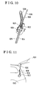
- FIG.10 illustrates a structure of the driving device
- Fig.11 illustrates an example in which the driving device is applied to an electrically operated lift-gate door unit of a vehicle.
- a lift-gate 101 provided to an opening 100 of the vehicle is electrically operated to open and close by means of a driving force generated by a motor 102 of the driving device.
- a clutch mechanism is provided between the motor 102 and a pinion gear 103.
- the driving device is actuated, the driving force generated by the motor 102 is transmitted to the pinion gear 103 via the clutch mechanism.
- the pinion gear 103 is engaged with a gear 105 formed on a side surface of a rack 104.
- An upper end of the rack 104 is connected to a lower end of the rod 106, and a top end of the rod 106 is connected to the lift-gate 101 so as to be rotatable.
- a slider 107 is provided between the rack 104 and the rod 106. The slider 107 is engaged with a guide groove 109 of the rail 108 so as to be slidable.
- the force transmission mechanism of the driving device needs to be reinforced so as to be durable against an excessive force.
- the force transmission mechanism is reinforced, it becomes inevitable that the structure of the force transmission mechanism becomes more complicated or a weight of the force transmission mechanism is increased.
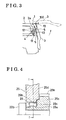
- Fig.3 illustrates a schematic view indicating a structure of an electrically operated lift-gate door unit 1 in which a driving device according to a first embodiment of the present invention is employed.
- the electrically operated lift-gate door unit 1 includes a lift-gate door 3 (open/close member) connected by means of a hinge 100 to an upper-rear portion of a vehicle body 2, an actuator 4 for electrically opening/closing the lift-gate door 3 and a damper stay 5 serving as a cushion member.
- the lift-gate door 3 pivotally rotates about the horizontal hinge axis 100.
- the actuator 4 includes a driving unit 11 and a rod 13. More specifically, the driving unit 11 (driving device) is fixed to a rear pillar 2a of the vehicle body 2 for outputting a driving force via an arm 12, and the rod 13 is used for connecting a top end portion of the arm 12 to a base end portion of the lift-gate door 3. The rod 13 is rotatably connected to the top end portion of the arm 12 and to the base end portion of the lift-gate door 3.
- a solid line in Fig.3 illustrates a closed state of the lift-gate door 3.
- the arm 12 In the closed state, the arm 12 is folded relative to the rod 13 so that the top end portion the arm 12 faces a bottom of the vehicle (downward direction in Fig.3).
- a chain double-dashed line in Fig.3 illustrates an opened state of the lift-gate door 3.
- the arm 12 In the opened state, the arm 12 is extended relative to the rod 13 so that the top end portion of the arm 12 faces a rear of the vehicle (rightward direction in Fig.3).
- the driving unit 11 causes the arm 12 and the rod 13 to rotate into the folded and extended states thereof , the lift-gate door 3 is brought into its closed and opened conditions, respectively.
- the damper stay 5 includes a gas piston into which high pressure gas is charged. One end of the damper stay 5 is connected to the rear portion of the vehicle body 2 and the other end of the damper stay 5 is connected to a base end of the lift-gate door 3.
- the damper stay 5 In an earlier half stage of the opening operation of the lift-gate door 3, the damper stay 5 generates a resultant force in a closed direction in conjunction with a lift-gate door's own weight so as to prevent the lift-gate door 3 from opening rapidly.
- the damper stay 5 In a later half stage of the opening operation of the lift-gate door 3, the damper stay 5 generates a resultant force in an opened direction in conjunction with a lift-gate door's own weight so as to assist the lift-gate door 3 to open.
- the damper stay 5 applies a force to the lift-gate door 3 on the basis of a balanced position at which the generated resultant force is balance out with the lift-gate's own weight.
- the damper stay 5 applies the force to the lift-gate door 3 in a closing direction, while after the lift-gate door 3 passes through the balanced position, the damper stay 5 applies the force to the lift-gate door 3 in an opening direction.
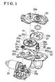
- Fig.1 illustrates an exploded perspective view, which indicates a structure of the driving unit 11.
- Fig.2 illustrates a partial cross section, which indicates a part of the driving unit 11.
- the driving unit 11 (open/close device) includes an electric motor 20 (driving source), a clutch mechanism 21, a pinion gear 24, an intermediate gear 25, an output shaft 26, a sector gear 27 and an arm 12.
- the clutch mechanism 21, the pinion gear 24, the intermediate gear 25, the output shaft 26, the sector gear 27 and the arm 12 act as functioned as a force transmission mechanism for transmitting a driving force from the electric motor 20 to the lift-gate door 3 (rod 13).
- Such parts that constitute the force transmission mechanism except for the clutch mechanism 21 comprise an intermediate mechanism 90.
- An upper case 23 and a lower case 22 support ratable the output shaft 26 , and the output shaft 26 is fitted to the sector gear 27.
- the sector gear 27, the intermediate gear 25 which engages with the sector gear 27, and the pinion gear 24 that engages with the intermediate gear 25 are housed in a space between the upper case 23 and the lower case 22 that are in opposition.
- the electric motor 20 (driving source) generates a driving force for actuating the lift-gate door 3 to open and close.
- the driving force generated by the electric motor 20 is transmitted to the clutch mechanism 21 via a set of worm (not shown) and worm wheel 20a.
- the clutch mechanism 21 is in the form of a known electromagnetic clutch that includes a plate 21a, a rotor 21b, a magnet coil 21c, and other elements.
- a plate 21a When an electric power is supplied to the magnet coil 21c, an attraction force is generated between the plate 21a and the rotor 21b, which establishes a frictional engagement therebetween (engaging state).
- the engaging state when the driving force generated of the electric motor 20 rotates the worm wheel 20a, the plate 21a connected to the worm wheel 20a is rotated in conjunction with the rotation of the worm wheel 20a. At this point, the frictional force generated between the plate 21a and the rotor 21b causes the rotor 21b to rotate together with the plate 21a.
- the rotor 21b is so connected to the output shaft 31 as to rotate concurrently therewith. Specifically, when the driving unit 11 is actuated, the clutch mechanism 21 is made engaging state, whereby the driving force of the electric motor 20 is transmitted to the output shaft 31 via the clutch mechanism 21.
- the pinion gear 24 is connected to the output shaft 31, which passes through a through hole 22a of the lower case 22, so as to be rotated therewith.
- a through hole 24a which penetrates in an axial direction of the pinion gear 24, is formed on the pinion gear 24, and a serration 24b, which meshes with a serration 31a of the output shaft 31, is formed on an inner peripheral surface of the through hole 24a.
- a shaft portion 22b of the lower case 22 is inserted into the intermediate gear 25 (driving member) in order to rotatably support the intermediate gear 25.
- the intermediate gear 25 includes a first gear portion 25a whose diameter is larger than a diameter of the pinion gear 24, and a second gear portion 25b whose diameter is smaller than the diameter of the first gear portion 25a.
- the first gear portion 25a meshes with the pinion gear 24, which enables the the electric motor 20 to rotate the intermediate gear 25.
- the output shaft 26 is formed into a stepped column-shape configuration.
- the output shaft 26 is rotatably supported by the lower case 22 in circumstances where a first shaft portion 26a formed on a base end side of the output shaft 26 is inserted into a bearing hole 22c formed on the lower case 22 so as to be rotatably supported by the lower case 22.
- the output shaft 26 includes a first serration shaft portion 26b, a second shaft portion 26c, a second serration shaft portion 26d and a screw portion 26e in a sequential order, and a diameter of the second shaft portion 26c is smaller than a diameter of the first serration shaft portion 26b, and a diameter of the second serration shaft portion 26d is smaller than the diameter of the second shaft portion 26c and a diameter of the screw portion 26e is smaller than the diameter of the second serration shaft portion 26d, and thus, diameters of the output shaft 26 are gradually decreased toward a top end side thereof.
- the first serration shaft portion 26b is fitted into a through hole 27a of the sector gear 27, and the second serration shaft portion 26d is fitted into a sleeve 12a fixed to the arm 12.
- the sector gear 27 is formed in a sector shape, and the output shaft 26 is fit into the through hole 27a of the sector gear 27 so that the sector gear 27 can rotate together with the output shaft 26.
- the through hole 27a penetrating in an axial direction is formed on the sector gear 27, and on an inner peripheral surface of the through hole 27a, a serration 27b is formed.
- the serration 27b corresponds to the serration of the first serration shaft portion 26b.
- the sector gear 27 is rotated together with the output shaft 26 in circumstances where the serration 27b of the sector gear 27 is fitted to the serration of the first serration shaft portion 26b.
- the sector gear 27 also meshes with the second gear portion 25b of the intermediate gear 25, and thus the sector gear 27 can be rotated along with the output shaft 26 by the intermediate gear 25.
- the arm 12 is connected to the second serration shaft portion 26d of the output shaft 26, which is inserted into a bearing hole 23b of the upper case 23 and extending rightward in Fig.2, so as to be rotated together with the output shaft 26.
- the sleeve 12a corresponding to the output shaft 26 (second serration shaft portion 26d) is fixed to a base end of the arm 12 so as to be extending in an axial direction.
- a serration 12b is formed so as to correspond to the serration of the second serration shaft portion 26d.
- the serration 12b of the arm 12 meshes with the serration of the output shaft 26 (second serration shaft portion 26d) so that the arm 12 rotates together with the output shaft 26. Further, in circumstances where the output shaft 26 is inserted into a hole of the arm 12 so as to be extending in rightward in Fig.2, a nut 32 is screwed to the screw portion 26e, which is formed on the top end of the output shaft 26.
- a torque limiter mechanism 29 is provided at the intermediate gear 25.
- a structure and a configuration of the torque limiter mechanism 29 will be explained in reference with Fig.4 and Fig.5A.
- Fig.4 illustrates an enlarged view of a part of the torque limiter mechanism 29, and
- Fig.5A illustrates a cross section of Fig.4 along a I-I line.
- the intermediate gear 25 includes a supporting member 25c (driven member), which has a second gear portion 25b, and a circular portion 25d (driving member), which has a first gear portion 25a (shown in Fig.2).
- the supporting member 25c and the circular portion 25d are provided independently.
- a driving force generated by the electric motor 20 is applied to the circular portion 25d, which is having the first gear portion 25a, by means of the pinion gear 24 (shown in Fig.2).
- the supporting member 25c is rotatably supported by the shaft portion 22b of the lower case 22 and inserted into the circular portion 25d.
- the torque limiter mechanism 29 is provided between the supporting member 25c and the circular portion 25d in a radial direction of the intermediate gear 25.
- the torque limiter mechanism 29 is comprised of plural protruding portions 29a formed on the supporting member 25c, plural protruding portions 29b formed on the circular portion 25d and a leaf spring 29c (load regulator).
- the protruding portions 29a are formed on an outer peripheral surface of the supporting member 25c so as to protrude in a radial direction from the outer peripheral surface of the supporting member 25c and to be equally spaced in a peripheral direction of the supporting member 25c.
- the protruding portions 29b are formed so as to correspond to the protruding portions 29a of the supporting member 25c.
- the protruding portions 29b are formed on an inner peripheral surface of the circular portion 25d so as to protrude in a radial direction from the inner peripheral surface of the circular portion 25d and to be equally spaced in a peripheral direction of the circular portion 25d.
- the leaf spring 29c is provided between the protruding portions 29a and the protruding portions 29b.
- the leaf spring 29c is made of a corrugated long elastic member such as a corrugated metal plate so as to be in a ring-shape.
- the leaf spring 29c includes plural convex portions 29d, each of which protrudes in a radially outward direction. More specifically, the plural convex portions 29d are formed on the leaf spring 29c sequentially in a peripheral direction.
- the protruding portions 29b of the circular portion 25d presses the convex portions 29d of the leaf spring 29c in a direction where the circular portion 25d rotates. Accordingly, the convex portions 29d of the leaf spring 29c presses the protruding portions 29a of the supporting member 25c in a direction where the circular portion 25d rotates, and thus the supporting member 25c rotates in a same direction as the rotation of the circular portion 25d rotates.
- the circular portion 25d and the supporting member 25c can be concurrently rotated by means of the leaf spring 29, as a result, the driving force applied to the circular portion 25d transmits to the sector gear 27 (shown in Fig.2) by means of the supporting member 25c having a second gear portion 25b.
- the leaf spring 29 is engaged with the protruding portions 29a and 29b at the intermediate gear's rotational direction side of the convex portions 29d.
- the torque limiter mechanism 29 including the leaf spring 29c is provided at the intermediate gear 25, however, the torque limiter mechanism 29 may be provided, for example, at the sector gear 27 (driving member) instead.
- the torque limiter mechanism 29 may be provided between the output shaft 26 (driving member) and the arm 12 (driving member).
- the output shaft 26 functions as an input portion of the driving force
- the arm 12 functions as an output portion of the driving force.
- a driving force generated by the electric motor 20 is transmitted from the circular portion 25d to the supporting member 25c by means of the torque limiter mechanism 29 in a radial direction of the intermediate gear 25.
- a driving force generated by the electric motor 20 is transmitted from a circular portion 250d to a supporting member 250c by means of a torque limiter mechanism 29' in an axial direction of an intermediate gear 250.
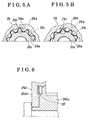
- Fig.5A illustrates a condition of the torque limiter mechanism 29 when the lift-gate door 3 is normally opened
- Fig.5B illustrates a condition of the torque limiter mechanism 29 when the opening operation of the lift-gate door 3 is rapidly decelerated.
- a predetermined load (rated load) is applied to the driving unit 11, which is connected to the lift-gate door 3 by means of the rod 13.
- the predetermined load is calculated on the basis of a weight of the lift-gate door 3.
- a driving force is transmitted from the circular portion 25d to the supporting member 25c by means of the leaf spring 29c of the torque limiter mechanism 29 as shown in Fig.5A.
- the driving force generated by the electric motor 20 is transmitted to the circular portion 25d by means of the first gear portion 25a, and then such driving force is further transmitted by means of the protruding portions 29b to the convex portion 29d of the leaf spring 29c. Then, the driving force is further transmitted to the supporting member 25c by means of the protruding portions 29a, and then further transmitted to the rod 13, which is connected to the lift-gate door 3 by means of the sector gear 27, the output shaft 26 and the arm 12.
- the driving force generated by the electric motor 20 is transmitted to the circular portion 25d by means of the clutch mechanism 21, however, because the rotation of the lift-gate door 3 is rapidly decelerated, the rotation of the supporting member 25, which is connected to the lift-gate door 3, is interrupted. Specifically, because a load applied to the supporting member 25c exceeds the level of the predetermined load (rated load), an excessive load whose level exceeds a load, which is corresponding to the rated load (threshold), is applied to the convex portion 29d of the leaf spring 29c by means of the protruding portions 29a and 29b.
- the convex portion 29d of the leaf spring 29c is supported by the protruding portions 29a of the supporting member 25c, and the convex portion 29d is pressed in a rotational direction of the circular portion 25d by means of the protruding portions 29b of the circular portion 25d relative to a point at which the convex portion 29d of the leaf spring 29c is supported by the protruding portions 29a of the supporting member 25c. And then, the leaf spring 29c is significantly and elastically deformed so that the protruding portions 29b of the circular portion 25d runs upon the convex portion 29d.
- the convex portion 29d of the leaf spring 29c is disengaged from the protruding portions 29b of the circular portion 25d in a rotational direction of the intermediate gear 25, as a result, the transmission of the driving force between the circular portion 25d and the supporting member 25c is interrupted. More specifically, the driving force transmitted from the electric motor 20 and the lift-gate door 3 can be conducted or interrupted by elastically deforming the leaf spring 29c on the basis of the predetermined load, which is set as a threshold.
- the protruding portions 29b of the circular portion 25d runs upon the convex portion 29d, however, another configuration can be applied alternatively.
- the protruding portions 29a of the supporting member 25c may run upon the convex portion 29d by deforming the shapes of the protruding portions 29a and 29b.
- the driving unit 11 includes the intermediate gear 25 for transmitting a driving force generated by the electric motor 20 to the lift-gate door 3, and the intermediate gear 25 includes the leaf spring 29c.
- the driving force transmitted from the electric motor 20 to the lift-gate door 3 can be interrupted by elastically deforming the leaf spring 29c on the basis of the predetermined load, which is set as the threshold.
- the threshold of the leaf spring 29c is set as an upper limit of the load that can be applied to driving members such as the intermediate gear 25, pinion gear 24 and the sector gear 27.
- the driving members can be designed so as to endure an excessive load that exceeds the threshold of the leaf spring 29c. More specifically the driving members can be designed so as to endure at least a load that equals to the threshold of the leaf spring 29c.
- reinforcements on the driving members can be minimized by setting the threshold of the leaf spring 29c preferably.
- the torque limiter mechanism 29 is provided between the supporting member 25c and the circular portion 25d in a radial direction of the intermediate gear 25, a dimension of the intermediate gear 25 cannot be increased in an axial direction. Thus, even when a space in the driving unit 11 into which the intermediate gear 25 is mounted is limited in an axial direction of the driving unit 11, the torque limiter mechanism 29 can be provided in the intermediate gear 25.
- the torque limiter mechanism 29 is provided between the supporting member 25c and the circular portion 25d in an axial direction of the intermediate gear 25, a dimension of the intermediate gear 25 cannot be increased in a radial direction. Thus, even when a space in the driving unit 11 into which the intermediate gear 25 is mounted is limited in a radial direction of the driving unit 11, the torque limiter mechanism 29 can be provided in the intermediate gear 25.
- the leaf spring 29c of the torque limiter mechanism 29 is made of an elastic member, even when the transmission of the driving force from the electric motor 20 to the lift-gate door 3 is interrupted, the leaf spring 29c may not be replaced on each occasion.
- the above mentioned driving unit 11 may be applied to a structure of other than the vehicle.
- the driving unit 11 may be used for opening/closing a window of a building.
- a driving unit 111 drives the electric lift-gate door unit 1 shown in Fig.3 so as to be opened/closed.
- the driving unit 111 includes an electric motor 20 (driving source), a clutch mechanism 21, a pinion gear 24, an intermediate gear 25 (driving member), an output shaft 26 (shaft), a sector gear 27 (driven member) and an arm 12 (connector) (outer member).
- the clutch mechanism 21, the pinion gear 24, the intermediate gear 25, the output shaft 26, the sector gear 27 and the arm 12 are functioned as a force transmission mechanism for transmitting a driving force from the electric motor 20 to the lift-gate door 3 (rod 13).
- Such parts except the clutch mechanism 21 comprises an intermediate mechanism 90.
- An upper case 23 and a lower case 22 support the output shaft 26 so as to be rotatable, and the output shaft 26 is fitted to the sector gear 27.
- the sector gear 27, the intermediate gear 25 which engages with the sector gear 27 and the pinion gear 24 that engages with the intermediate gear 25 are housed in a space between the upper case 23 and the lower case 22.
- the electric motor 20 (driving source) generates a driving force for actuating the lift-gate door 3 so as to be opened and closed.
- the driving force generated by the electric motor 20 is transmitted to the clutch mechanism 21 by means of a worm (not shown) and a worm wheel 20a.
- the clutch mechanism 21 is a known electromagnetic clutch that is comprised of a plate 21a, a rotor 21b and a magnet coil 21c.
- a power is supplied to the magnet coil 21c, an attraction force is generated between the plate 21a and the rotor 21b, so that the plate 21a frictionally engages with the rotor 21b (engaging state).
- the engaging state when the worm wheel 20a is rotated by a driving force generated by the electric motor 20, the plate 21a connected to the worm wheel 20a is rotated in conjunction with the rotation of the worm wheel 20a.
- the rotor 21b is rotated in conjunction with the plate 21a. Further, the rotor 21b is connected to the output shaft 31 so as to be concurrently rotatable. Specifically, when the driving unit 11 is actuated, the clutch mechanism 21 becomes in an engaging state, and then the driving force generated by the electric motor 20 is transmitted to the output shaft 31 by means of the clutch mechanism 21.
- the pinion gear 24 is connected to the output shaft 31, which is inserted into a through hole 22a of the lower case 22, so as to be rotated concurrently.
- a through hole 24a which penetrates in an axial direction of the pinion gear 24, is formed on the pinion gear 24, and a serration 24b, which meshes with a serration 31a of the output shaft 31, is formed on an inner peripheral surface of the through hole 24a.
- a shaft portion 22b of the lower case 22 is inserted into the intermediate gear 25 (driving member) in order to rotatably support the intermediate gear 25.
- the intermediate gear 25 includes a first gear portion 25a whose diameter is larger than a diameter of the pinion gear 24, and a second gear portion 25b whose diameter is smaller than the diameter of the first gear portion 25a.
- the first gear portion 25a meshes with the pinion gear 24 so that the intermediate gear 25 is rotated by a driving force generated by the electric motor 20.
- the output shaft 26 is formed in a column-shape having plural diameters so as to be in a stepped shape in a side view.
- the output shaft 26 is rotatably supported by the lower case 22 in circumstances where a first shaft portion 26a formed on a base end side of the output shaft 26 is inserted into a bearing hole 22c formed on the lower case 22 so as to be rotatably supported by the lower case 22.
- the output shaft 26 includes a first serration shaft portion 26b, a second shaft portion 26c, a second serration shaft portion 26d and a screw portion 26e in a sequential order, and a diameter of the second shaft portion 26c is smaller than a diameter of the first serration shaft portion 26b, and a diameter of the second serration shaft portion 26d is smaller than the diameter of the second shaft portion 26c and a diameter of the screw portion 26e is smaller than the diameter of the second serration shaft portion 26d, and thus, diameters of the output shaft 26 are gradually decreased toward a top end side thereof.
- the first serration shaft portion 26b is fitted into a through hole 27a of the sector gear 27, and the second serration shaft portion 26d is fitted into a sleeve 12a fixed to the arm 12.
- the sector gear 27 is formed in a sector shape, and the output shaft 26 is fit into the through hole 27a of the sector gear 27 so that the sector gear 27 can rotate together with the output shaft 26.
- the through hole 27a penetrating in an axial direction is formed on the sector gear 27, and on an inner peripheral surface of the through hole 27a, a serration 27b is formed.
- the serration 27b corresponds to the serration of the first serration shaft portion 26b.
- the sector gear 27 is rotated together with the output shaft 26 in circumstances where the serration 27b of the sector gear 27 is fitted to the serration of the first serration shaft portion 26b.
- the sector gear 27 also meshes with the second gear portion 25b of the intermediate gear 25, and thus the sector gear 27 can be rotated along with the output shaft 26 by the intermediate gear 25.
- the arm 12 is connected to the second serration shaft portion 26d of the output shaft 26, which is inserted into a bearing hole 23b of the upper case 23 and extending rightward in Fig.7, so as to be rotated together with the output shaft 26.
- the sleeve 12a corresponding to the output shaft 26 (second serration shaft portion 26d) is fixed to a base end of the arm 12 so as to be extending in an axial direction.
- a serration 12b is formed so as to correspond to the serration of the second serration shaft portion 26d.
- the serration 12b of the arm 12 meshes with the serration of the output shaft 26 (second serration shaft portion 26d) so that the arm 12 rotates together with the output shaft 26. Further, in circumstances where the output shaft 26 is inserted into a hole of the arm 12 so as to be extending in rightward in Fig.2, a nut 32 is screwed to the screw portion 26e, which is formed on the top end of the output shaft 26.
- a torque limiter mechanism 129 is provided at the intermediate gear 25.
- a structure and a configuration of the torque limiter mechanism 129 will be explained in reference with Fig.8A.
- Fig.8A illustrates a cross section of Fig.7 along a II-II line.
- a torque limiter mechanism 129 is provided between the serration 12b of the arm 12 and the second serration shaft portion 26d of the output shaft 26.
- a structure and a configuration of the torque limiter mechanism 129 will be explained with reference to Fig.8A.
- Fig.8A illustrates a cross section along a II-II line of the torque limiter mechanism 129 illustrates in Fig.7.
- the torque limiter mechanism 129 includes plural protruding portions 26p, which is formed on the second serration shaft portion 26d of the output shaft 26, and plural protruding portions 12p, which is formed on the serration portion 12b of the arm 12.
- the protruding portions 26p are extending in an axial direction of the output shaft 26 and the protruding portions 12p (load regulator) are extending in an axial direction of the arm 12, and the protruding portions 26p are engaged with the protruding portions 12p.
- the driving force generated by the electric motor 20 is transmitted to the arm 12 so that the protruding portions 26p of the output shaft 26 presses the protruding portions 12p of the arm 12, as a result, the arm 12 is rotated.
- the protruding portions 12p of the arm 12 and the protruding portions 26p of the output shaft 26 are applying loads to each other.
- a load is applied to the protruding portions 12p of the arm 12 from the protruding portions 26p of the output shaft 26.
- the more the level of the driving force which is transmitted from the output shaft 26 to the arm 12 becomes large the more the level of the load, which is required for pressing and moving the protruding portions 12p of the arm 12 by the protruding portions 26p, becomes large, as a result, a reaction force, specifically a load applied to the protruding portions 12p, becomes large.
- the strength of the arm 12 is set at a level at which the protruding portions 12p can be broken or deformed when a load applied to the protruding portions 12p exceeds a predetermined value (threshold).
- the strength of the arm 12 can be obtained by preferably selecting a material of the arm 12 or the output shaft 26 that has a preferable hardness.
- the shape of the protruding portions 12p of the arm 12 is not limited to the shape explained in the second embodiment.
- the protruding portions 12p may be formed in another shape if they can be preferable broken when the load applied thereto exceeds the predetermined value (threshold).
- the driving force generated by the electric motor 20 is transmitted by means of the protruding portions 12p and 26p of the torque limiter mechanism 129, however, the driving force can be transmitted by means of a ring member 130 (load regulator) (connector) (inner member) which is provided between the protruding portions 26p of the output shaft 26 and the protruding portions 12p of the arm 12 as shown in Fig.9.
- a material of the ring member 130 can be selected preferably so that the protruding portions 130p of the ring member 130 can be broken when the driving force transmitted between the output shaft 26 and the arm 12 exceeds a predetermined value.
- a space 31 is provided for housing the broken protruding portions 130p between the ring member 130 and the output shaft 26 (second serration shaft portion 26d), or between the ring member 130 and the arm 12 (serration portion 12b).
- the torque limiter mechanism 129 is provided between the output shaft 26 and the arm 12, however, the torque limiter mechanism 129 may be provided between the output shaft 26 and the sector gear 27 (driving member).
- Fig.8A illustrates a condition of the torque limiter mechanism 129 when the lift-gate door 3 is normally opened
- Fig.8B illustrates a condition of the torque limiter mechanism 129 when the opening operation of the lift-gate door 3 is rapidly decelerated.
- a power is supplied to the electric motor 20 in order to actuate the driving unit 11.
- a driving force is generated by the electric motor 20, and such driving force is transmitted to the output shaft 31 in order to rotate the output shaft 31 is rotated.
- Such driving force is further transmitted to the arm 12 through the pinion gear 24, the intermediate gear 25 (the first gear portion 25a and the second gear portion 25b), the sector gear 27 and the output shaft 26, and further transmitted by means of the rod 13 to the lift-gate door 3.
- the lift-gate door 3 is actuated so as to be opened as shown in the chain double-dashed line in Fig.3.
- a predetermined load (rated load) is applied to the driving unit 111, which is connected to the lift-gate door 3 by means of the rod 13.
- a driving force is transmitted from the output shaft 26 to the arm 12 by means of the protruding portions 26p of the torque limiter mechanism 129 as shown in Fig.8 A.
- driving force transmitted to the output shaft 26 is further transmitted to arm 12 by means of the protruding portions 26p pressing and moving the protruding portions 12p of the arm 12.
- the driving force generated by the electric motor 20 is transmitted to the output shaft 26 by means of the clutch mechanism 21, however, because the rotation of the lift-gate door 3 is rapidly decelerated, the rotation of the arm 12, which is connected to the lift-gate door 3, is interrupted.
- the protruding portions 26p of the output shaft 26 presses and moves the protruding portions 12p of the arm 12, whose rotation is interrupted, an excessive load is applied from the protruding portions 26p of the output shaft 26 to the protruding portions 12p of the arm 12.
- the protruding portions 12p of the arm 12 is broken so as to interrupt the transmission of the driving force from the output shaft 26 to the arm 12.
- the transmission of the driving force from the electric motor 20 to the lift-gate door 3 is interrupted by means of the protruding portions 12p which is irreversibly deformed on the basis of the predetermined load, which is set as the threshold.
- the arm 12 that transmits the driving force generated by the electric motor 20 includes a protruding portions 12p.
- the transmission of the driving force between electric motor 20 and the lift-gate door 3 can be interrupted by irreversibly deforming the protruding portions 12p on a basis of the threshold that is set by the predetermined load.
- the protruding portions 12p is irreversibly deformed so as to interrupt the driving force transmitted between the electric motor 20 and the lift-gate door 3.
- the threshold of the protruding portions 12p is set as an upper limit of the load that can be applied to driving members such as the arm 12, the intermediate gear 25 and the sector gear 27.
- the driving members can be designed so as to endure an excessive load that exceeds the threshold of the protruding portions 12p. More specifically the driving members can be designed so as to endure at least a load that equals to the threshold of the protruding portions 12p.
- reinforcements of the driving members can be minimized by setting the threshold of the protruding portions 12p preferably.
- the ring member 130 is provided between the output shaft 26 and the arm 12. In this configuration, the transmission of the driving force between the output shaft 26 and the arm 12 is interrupted by breaking the ring member 130. Thus, when the driving unit 111 needs to be fixed, only the ring member 130 can be replaced, and there is no need to replace the driving members such as the output shaft 26 and the arm 12.
- the driving unit 111 may be applied to a structure of other than the vehicle. For example, the driving unit 111 may be used for opening/closing a window of a building.
Landscapes
- Power-Operated Mechanisms For Wings (AREA)
- Portable Nailing Machines And Staplers (AREA)
- Toilet Supplies (AREA)
- Mechanical Control Devices (AREA)
Abstract
Description
Claims (18)
- A driving device (11) for driving an open/close member (3) that is designed to open and close an open portion of a body comprising:characterized in that further comprising a load regulator (29c, 12, 130) for interrupting the driving force transmission when an excessive force is applied to the force transmission mechanism (21, 24, 25, 26, 27, 12) from the open/close member (3).a driving source (20) generating a driving force; anda force transmission mechanism (21, 24, 25, 26, 27, 12) disposed between the driving source (20) and the open/close member (3) and serving for transmitting the driving force thereto,
- A driving device (11) as set forth in Claim 1, wherein the body is a vehicle, and the open/close member (3) is a lift gate door (3) that is attached to an aft end of a roof of the vehicle so as to rotate pivotally about a generally horizontal hinge axis (100).
- A driving device (11) as set forth in Claim 1, wherein the load regulator (29c) is provided in the force transmission mechanism (21, 24, 25, 26, 27, 12), is of elasticity, and is deformed upon receipt of the excessive force so as to interrupt the driving force transmission.
- A driving device (11) as set forth in Claim 2, wherein the elasticity is of a restoring ability.
- A driving device (11) as set forth in Claim 1, wherein the load regulator (12, 130) is provided in the force transmission mechanism (21, 24, 25, 26, 27, 12), is of rigidity, and is brought into breakage upon receipt of the excessive force so as to interrupt the driving force transmission.
- A driving device (11) as set forth in Claim 1, wherein the force transmission mechanism (21, 24, 25, 26, 27, 12) includes a clutch mechanism (21), which is connected to the driving source (20), and an intermediate mechanism (90), which is connected to the open/close member (3), the intermediate mechanism (90) being provided with the load regulator (29c, 12, 130).
- A driving device (11) as set forth in Claim 6, wherein the intermediate mechanism (90) has a driving member (25d), which is connected to the clutch mechanism (21), and a driven member (25c), which is connected to the open/close member (3), and the load regulator (29c) is provided between the driving member (25d) and the driven member (25c), the load regulator being expected to be deformed, upon receipt of the excessive force, in order to interrupt the driving force transmission from the driving member (25d) to the driven member (25c).
- A driving device (11) as set forth in Claim 7, the load regulator (29c) is returned to its original shape upon release of the excessive force.
- A driving device (11) as set forth in Claim 7, wherein opposed geared surfaces are provided on the respective driving member (25d) and the driven member (25c), and the load regulator (29c) including a ring member (29c) is made of a corrugated metal plate.
- A driving device (11) as set forth in Claim 9, wherein the geared surfaces of the respective driving member (25d) and the driven member (25c) are opposed with each other in a radial direction.
- A driving device (11) as set forth in Claim 10, wherein the geared surfaces of the respective driving member (25d) and the driven member (25c) are opposed with each other in an axial direction.
- A driving device (11) as set forth in Claim 9, wherein the ring member is a ring-shaped leaf spring (29c) made of a corrugated metal sheet.
- A driving device (11) as set forth in Claim 6, wherein the intermediate mechanism (90) has a driving member (25), which is connected to the clutch mechanism (21), and a driven member (27), which is connected to the open/close member (3), and the load regulator (12, 130) is provided between the driving member (25) and the driven member (27), the load regulator (12, 130) being expected to be broken, upon receipt of the excessive force, to interrupt the driving force transmission between the driving member (25) and the driven member (27).
- A driving device (11) as set forth in Claim 13, wherein the load regulator (12, 130) serves as a connector (12, 130) via which the driven member (27) is connected to the open/close member (3).
- A driving device (11) as set forth in Claim 14, wherein the connector (12, 130) is in meshing engagement with a shaft (26) connected to the driven member (27).
- A driving device (11) as set forth in Claim 15, wherein the connector (12, 130) is formed into a cylinder structure in which the shaft (26), which is connected to the driven member (27), is inserted.
- A driving device (11) as set forth in Claim 16, wherein the cylindrical-shaped connector (12, 130) is in the form of a two separate member structure having an inner member (130) and an outer member (12), and the inner member (130) is designed to be broken upon receipt of the excessive force.
- A driving device (11) as set forth in Claim 17, wherein the inner member (130) and the outer member (12) are in meshing engagement with each other.
Applications Claiming Priority (4)
| Application Number | Priority Date | Filing Date | Title |
|---|---|---|---|
| JP2004157178 | 2004-05-27 | ||
| JP2004157179 | 2004-05-27 | ||
| JP2004157179A JP2005336858A (en) | 2004-05-27 | 2004-05-27 | Opening and closing device for opening and closing body for vehicle |
| JP2004157178A JP2005336857A (en) | 2004-05-27 | 2004-05-27 | Opening and closing device for opening and closing body for vehicle |
Publications (2)
| Publication Number | Publication Date |
|---|---|
| EP1600592A2 true EP1600592A2 (en) | 2005-11-30 |
| EP1600592A3 EP1600592A3 (en) | 2012-10-17 |
Family
ID=34937027
Family Applications (1)
| Application Number | Title | Priority Date | Filing Date |
|---|---|---|---|
| EP05011548A Withdrawn EP1600592A3 (en) | 2004-05-27 | 2005-05-27 | Driving device for driving and open/close member |
Country Status (2)
| Country | Link |
|---|---|
| US (1) | US7201430B2 (en) |
| EP (1) | EP1600592A3 (en) |
Cited By (2)
| Publication number | Priority date | Publication date | Assignee | Title |
|---|---|---|---|---|
| EP2017423A1 (en) * | 2007-07-20 | 2009-01-21 | Sesamo S.r.l. | Automatic system for swinging doors |
| CN113302821A (en) * | 2019-01-18 | 2021-08-24 | 盖慈有限公司 | Drive device for a revolving door |
Families Citing this family (13)
| Publication number | Priority date | Publication date | Assignee | Title |
|---|---|---|---|---|
| JP4837338B2 (en) * | 2005-09-07 | 2011-12-14 | 株式会社ミツバ | Electric switchgear for vehicles |
| US7566087B2 (en) * | 2006-08-18 | 2009-07-28 | Dura Global Technologies, Inc. | Power closure assembly |
| JP4994045B2 (en) * | 2007-01-12 | 2012-08-08 | 三井金属アクト株式会社 | Opening and closing device for vehicle opening and closing body |
| DE102008045904B3 (en) * | 2008-09-04 | 2009-11-05 | Audi Ag | Motor vehicle, has rear flap movable from closing position to opening position, engine coupled with gear wheel, and gear rod coupled with rear flap, where gear rod is pivotable around axis of rotation relative to gear wheel in two modes |
| DE102008045899B4 (en) | 2008-09-04 | 2016-07-21 | Audi Ag | Motor vehicle with mechanism for moving a flap by means of a motor |
| DE102008061395B4 (en) | 2008-09-04 | 2013-09-26 | Audi Ag | Motor vehicle with mechanism for moving a flap or scissor door |
| DE102008045901A1 (en) | 2008-09-04 | 2010-03-25 | Audi Ag | Motor vehicle, has toggle lever with pivot arm i.e. offset lever, movable by motor, and another pivot arm connected with former pivot arm, where former pivot arm is curved or angled in direction along its pivot axis |
| DE102008045903B4 (en) | 2008-09-04 | 2013-10-31 | Audi Ag | Motor vehicle with mechanism for moving a flap |
| DE102008045900A1 (en) | 2008-09-04 | 2009-04-09 | Audi Ag | Motor vehicle, has rear flap transported from closing position to opening position against gravity force, and body moved using flap during rotation of wheel, where body is not movable opposite to flap |
| DE102008045906A1 (en) | 2008-09-04 | 2009-05-07 | Audi Ag | Car has opening panel, e.g. boot lid, operated by spindle drive mounted in water drain channel so that axis around which panel swivels is below its line of operation in all positions |
| DE102008045905A1 (en) | 2008-09-04 | 2009-11-12 | Audi Ag | Motor vehicle has hatch which is brought in open position from closed position against gravity and spindle drive is provided which comprises motor, spindle and spindle nut to move hatch |
| US8366176B2 (en) * | 2010-06-29 | 2013-02-05 | Mitsui Kinzoku Act Corporation | Vehicle door-open limiting device |
| US8764090B2 (en) | 2011-08-11 | 2014-07-01 | Toyota Motor Engineering & Manufacturing North America, Inc. | Vehicles incorporating tailgate energy management systems |
Citations (1)
| Publication number | Priority date | Publication date | Assignee | Title |
|---|---|---|---|---|
| JP2003312268A (en) | 2002-04-19 | 2003-11-06 | Oi Seisakusho Co Ltd | Automatic back door opening and closing device |
Family Cites Families (12)
| Publication number | Priority date | Publication date | Assignee | Title |
|---|---|---|---|---|
| US3422572A (en) * | 1966-09-21 | 1969-01-21 | Gen Motors Corp | Vehicle body closure operator |
| US4702122A (en) * | 1986-09-02 | 1987-10-27 | The Scott & Fetzer Company | Bi-directional advance gear having a torque limiting clutch |
| US5448856A (en) * | 1994-08-18 | 1995-09-12 | Chrysler Corporation | Vehicle body with powered lift type tailgate |
| US5896703A (en) * | 1998-06-26 | 1999-04-27 | General Motors Corporation | Power liftgate cable drive |
| DE19856100C2 (en) * | 1998-12-04 | 2001-08-23 | Siemens Ag | Geared motor actuator, in particular motorized closing part drive for a motor vehicle |
| JP4006174B2 (en) * | 2000-09-20 | 2007-11-14 | 株式会社大井製作所 | Opening and closing device for opening and closing body in vehicle |
| US6318025B1 (en) * | 2000-10-06 | 2001-11-20 | Delphi Technologies, Inc. | Vehicle liftgate power operating system |
| US6719356B2 (en) * | 2001-04-26 | 2004-04-13 | Litens Automotive | Powered opening mechanism and control system |
| JP2003041853A (en) * | 2001-07-31 | 2003-02-13 | Araco Corp | Opening and closing device for rear door of motor vehicle |
| JP3709545B2 (en) * | 2002-09-06 | 2005-10-26 | 三井金属鉱業株式会社 | Door opener |
| JP4254212B2 (en) * | 2002-11-27 | 2009-04-15 | アイシン精機株式会社 | Opening / closing control system for vehicle opening / closing body |
| JP4577552B2 (en) * | 2004-07-08 | 2010-11-10 | アイシン精機株式会社 | Opening and closing body drive device |
-
2005
- 2005-05-27 EP EP05011548A patent/EP1600592A3/en not_active Withdrawn
- 2005-05-27 US US11/138,283 patent/US7201430B2/en not_active Expired - Fee Related
Patent Citations (1)
| Publication number | Priority date | Publication date | Assignee | Title |
|---|---|---|---|---|
| JP2003312268A (en) | 2002-04-19 | 2003-11-06 | Oi Seisakusho Co Ltd | Automatic back door opening and closing device |
Cited By (2)
| Publication number | Priority date | Publication date | Assignee | Title |
|---|---|---|---|---|
| EP2017423A1 (en) * | 2007-07-20 | 2009-01-21 | Sesamo S.r.l. | Automatic system for swinging doors |
| CN113302821A (en) * | 2019-01-18 | 2021-08-24 | 盖慈有限公司 | Drive device for a revolving door |
Also Published As
| Publication number | Publication date |
|---|---|
| EP1600592A3 (en) | 2012-10-17 |
| US20050275237A1 (en) | 2005-12-15 |
| US7201430B2 (en) | 2007-04-10 |
Similar Documents
| Publication | Publication Date | Title |
|---|---|---|
| US7201430B2 (en) | Driving device for driving an open/close member | |
| US10822856B2 (en) | Electromechanical strut with electromechanical brake and method of allowing and preventing movement of a closure member of a vehicle | |
| US10273735B2 (en) | Linear drive actuator for a movable vehicle panel | |
| EP3734007B1 (en) | Actuator for powered vehicle closure | |
| CN110056282B (en) | Electromechanical strut including planetary gear set with integral flex link | |
| KR20210096651A (en) | Nut-lead screw type automatic door opening and closing mechanism, automobile automatic door and automobile | |
| US7959204B2 (en) | Electric opening/closing device for vehicle | |
| EP2712987A2 (en) | Switching mechanism | |
| CN111236785A (en) | Motor-free balance support rod | |
| EP1892363A2 (en) | Power closure assembly | |
| GB2424045A (en) | Centrifugal clutch which is rotationally balanced when engaged | |
| JP4258322B2 (en) | Power luggage door hinge structure | |
| WO2010053062A1 (en) | Device for automatically opening and closing door-like member | |
| JP6047371B2 (en) | Open / close drive device | |
| WO2005049947A1 (en) | System for power closing of a self rising closure panel | |
| EP1826047A2 (en) | Electromechanical strut | |
| US7810280B2 (en) | Automatic opening/closing apparatus for vehicle | |
| JP2001012145A (en) | Opening and closing device having damper | |
| CN119084480A (en) | Adjusting drive | |
| JP2005336858A (en) | Opening and closing device for opening and closing body for vehicle | |
| US20070033876A1 (en) | Motion transmission for tailgate | |
| JP2010246880A (en) | Electric toilet seat device | |
| JP2005336857A (en) | Opening and closing device for opening and closing body for vehicle | |
| JP2006290296A (en) | Door checker | |
| JP2001012146A (en) | Method and device for opening and closing door |
Legal Events
| Date | Code | Title | Description |
|---|---|---|---|
| PUAI | Public reference made under article 153(3) epc to a published international application that has entered the european phase |
Free format text: ORIGINAL CODE: 0009012 |
|
| AK | Designated contracting states |
Kind code of ref document: A2 Designated state(s): AT BE BG CH CY CZ DE DK EE ES FI FR GB GR HU IE IS IT LI LT LU MC NL PL PT RO SE SI SK TR |
|
| AX | Request for extension of the european patent |
Extension state: AL BA HR LV MK YU |
|
| RIC1 | Information provided on ipc code assigned before grant |
Ipc: E05F 15/00 20060101ALI20120514BHEP Ipc: E05F 15/12 20060101AFI20120514BHEP |
|
| PUAL | Search report despatched |
Free format text: ORIGINAL CODE: 0009013 |
|
| AK | Designated contracting states |
Kind code of ref document: A3 Designated state(s): AT BE BG CH CY CZ DE DK EE ES FI FR GB GR HU IE IS IT LI LT LU MC NL PL PT RO SE SI SK TR |
|
| AX | Request for extension of the european patent |
Extension state: AL BA HR LV MK YU |
|
| RIC1 | Information provided on ipc code assigned before grant |
Ipc: E05F 15/00 20060101ALI20120912BHEP Ipc: E05F 15/12 20060101AFI20120912BHEP |
|
| AKY | No designation fees paid | ||
| REG | Reference to a national code |
Ref country code: DE Ref legal event code: R108 |
|
| REG | Reference to a national code |
Ref country code: DE Ref legal event code: R108 Effective date: 20130626 |
|
| STAA | Information on the status of an ep patent application or granted ep patent |
Free format text: STATUS: THE APPLICATION IS DEEMED TO BE WITHDRAWN |
|
| 18D | Application deemed to be withdrawn |
Effective date: 20130418 |