EP1600203A1 - Apparatus for simultaneous dry desulfurization/denitrification - Google Patents
Apparatus for simultaneous dry desulfurization/denitrification Download PDFInfo
- Publication number
- EP1600203A1 EP1600203A1 EP03786375A EP03786375A EP1600203A1 EP 1600203 A1 EP1600203 A1 EP 1600203A1 EP 03786375 A EP03786375 A EP 03786375A EP 03786375 A EP03786375 A EP 03786375A EP 1600203 A1 EP1600203 A1 EP 1600203A1
- Authority
- EP
- European Patent Office
- Prior art keywords
- denitration
- dry desulfurization
- exhaust gas
- radical
- set forth
- Prior art date
- Legal status (The legal status is an assumption and is not a legal conclusion. Google has not performed a legal analysis and makes no representation as to the accuracy of the status listed.)
- Granted
Links
Images







Classifications
-
- B—PERFORMING OPERATIONS; TRANSPORTING
- B01—PHYSICAL OR CHEMICAL PROCESSES OR APPARATUS IN GENERAL
- B01D—SEPARATION
- B01D53/00—Separation of gases or vapours; Recovering vapours of volatile solvents from gases; Chemical or biological purification of waste gases, e.g. engine exhaust gases, smoke, fumes, flue gases, aerosols
- B01D53/34—Chemical or biological purification of waste gases
- B01D53/46—Removing components of defined structure
- B01D53/60—Simultaneously removing sulfur oxides and nitrogen oxides
Definitions
- the present invention relates to the apparatus for simultaneous dry desulfurization and denitration to induce chain reaction using OH radicals, thereby to simultaneously oxidize nitrogen monoxide and sulfur dioxide, which is utilized for removal of such atmospheric contaminants as nitrogen and sulfur compounds contained in exhaust gas.
- Fossil fuels such as coal contains sulfur compounds as impurities, and most of sulfur content is exhausted as sulfur dioxide upon combustion under excess of oxygen. Sulfur dioxide contained in exhaust gas is generally removed by wet process using a scrubber to contact exhaust gas with the mist of absorbent and absorb and remove sulfur dioxide (Refer, for example, to the Japanese laid open Patent Application (JP H10-202049-A)).
- a dry exhaust gas treating method which oxidizes sulfur dioxide gas by passing sulfur dioxide in exhaust gas through pulsed corona discharge region, and removes it by adsorbing on fine powder of calcium oxide or others as an adsorbent (Refer, for example, to the Japanese laid open Patent Application (JP H05-228330-A)). Further, the art to convert sulfur dioxide gas to sulfur trioxide gas with vanadium pentoxide (V 2 O 5 ) as an oxidizing catalyst was disclosed in the Japanese laid open Patent Application (JP 2001-11041-A).
- the object of the present invention is to solve such problems, and to offer an apparatus for simultaneous dry desulfurization and denitration of high efficiency and low cost, capable of treating exhaust gas by dry process without catalysts or others, and of simultaneous oxidation of nitrogen monoxide and sulfur dioxide by chain reaction using OH radicals.
- an apparatus for simultaneous dry desulfurization and denitration of the present invention is characterized in that, in a dry exhaust gas treating apparatus to treat exhaust gas of high temperature, it is comprised of a reactor and an OH radical supplier, and treats exhaust gas by supplying either OH radicals or OH radical initiators to the reactor into which exhaust gas is introduced, and by oxidizing either sulfur or nitrogen compounds in exhaust gas, or both of them simultaneously.
- the reactor may be provided with an inner and an outer tubes coaxially spaced, and a radical supplying inlet to supply either OH radicals or OH radical initiators to an inner tube.
- a radical supplying inlet to supply either OH radicals or OH radical initiators to an inner tube.
- the reactor is preferably provided with injectors to supply OH radicals and OH radical initiators. It is advantageous if said injectors are provided in plurality with different lengths capable of multi-step blow-in.
- the reactor may also be provided with either a shower pipe or a spray nozzle, or both, to supply either OH radicals or OH radical initiators. Said reactor may be either horizontal or vertical type.
- the OH radical supplier may preferably have a radical generation source and a gas supplying system.
- the OH radical initiator is preferably nitric acid. OH radicals are generated by pyrolysis of nitric acid.
- the sulfur compound in exhaust gas is sulfur dioxide
- the nitrogen compound is nitrogen monoxide
- sulfur dioxide and nitrogen monoxide can be simultaneously oxidized with either OH radicals or OH radicals generated from OH radical initiators as the initiator.
- the oxides generated from simultaneous oxidation are sulfur trioxide and nitrogen dioxide.
- the apparatus for simultaneous dry desulfurization and denitration of such aspect induces chain reaction with supplied OH radicals as the initiator, simultaneously oxidizes sulfur dioxide and nitrogen monoxide to sulfur trioxide and nitrogen dioxide, and exhausts them. Therefore, the apparatus for simultaneous dry desulfurization and denitration of the present invention is capable of exhaust gas treating in dry process without using catalysts and others at high efficiency and low cost.
- the apparatus for simultaneous dry desulfurization and denitration of the above-mentioned aspect is preferably provided with a sulfuric acid recovery apparatus to recover sulfur trioxide formed by oxidation process of exhaust gas as either sulfuric acid or gypsum, or both.
- the above-mentioned apparatus for simultaneous dry desulfurization and denitration is preferably provided with a nitric acid recovery apparatus to recover nitrogen dioxide formed by oxidation process of exhaust gas as nitric acid. It may also be provided with a nitric acid recovery apparatus to recover OH radical suppliers as nitric acid. The recovered nitric acid may be reused by recycling as OH radical suppliers.
- the apparatus for simultaneous dry desulfurization and denitration of such aspect recovers sulfuric acid from sulfur trioxide formed by oxidative treating of exhaust gas, sulfuric acid or gypsum can be recovered efficiently.
- Nitrogen dioxide formed by oxidative treating of exhaust gas can also be recovered as nitric acid, and further, in case that nitric acid is supplied as an OH radical supplier, nitric acid can be recovered and recycled, thereby reused as an OH radical supplier.
- O 2 is oxygen gas contained in exhaust gas.
- M is the gas not involved in reactions, for example, N 2 , and CO 2 and H 2 or the like added together with N 2 .
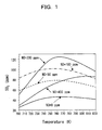
- Fig.1 is a graph showing the calculation result of temperature dependency of SO 3 generation concentration on the added amount of NO with HNO 3 kept constant.
- the abscissa is temperature (K)
- the ordinate is SO 3 concentration (ppm).
- the calculation condition here is the hypothesis that the reaction proceeds in adiabatic state, and that the reaction time is one second.
- SO 2 concentration in exhaust gas is 2000ppm
- HNO 3 concentration is 1000ppm.
- Fig. 3 is a graph showing the calculated values of mole fraction of sulfur compounds between 400 and 1000K. Its ordinate is mole fraction of sulfur compounds, and abscissa is temperature (K). It is seen from this that SO 3 is more stable than H 2 SO 4 and SO 2 at 600 - 850K, and especially, its mole fraction reaches the maximum value at 650 - 800K. Therefore, it is conceivable that SO 2 is easily oxidized at 650 - 800K.
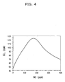
- its ordinate is SO 3 concentration
- abscissa is NO concentration (ppm).
- HNO 3 concentration is 100ppm. It is seen that SO 3 conversion increases till NO concentration of about 200 ppm, and decreases with NO concentration above that.
- its ordinate is SO 3 concentration
- abscissa is HNO 3 concentration (ppm).
- SO 2 concentration is 1000ppm
- NO concentration is 200ppm.
- SO 3 conversion is about 15, 16, and 17%, respectively, with HNO 3 concentration 200, 300, and 400 ppm.
- SO 3 generation increases with the increase of HNO 3 concentration till HNO 3 concentration of about 100 ppm.
- NO conversion to NO 2 (hereinafter, to be called NO 2 conversion) is 80 to 90%.
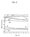
- Fig. 6 is a graph showing the calculation result of the change with time of various chemical species in oxidation reaction of SO 2 and NO of Fig. 5.
- its ordinate is mole fraction
- abscissa is time (second).
- the condition is same as in Fig. 1 except that temperature is 750K, NO concentration is 200 ppm, and SO 2 concentration is 1000ppm. It is seen from the figure that SO 2 and NO are oxidized by HNO 3 pyrolysis to form about 0.2 second. It is also seen from this that main oxidation products are SO 3 and NO 2 , and NO is scarcely formed, and added NO is almost completely oxidized to NO 2 .
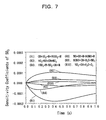
- Fig. 7 is a graph showing the calculation result of sensitivity coefficients of major elementary reactions to SO 3 concentration under the calculation conditions of Fig. 6.
- the initial conditions are same as in Fig. 6.
- its ordinate is the sensitivity coefficients of major elementary reactions to generate SO 3
- abscissa is time (second).
- the most important reactions for SO 3 generation are chemical reaction equations (R1), (R3), and (R4) (Refer to (R1), (R3), and (R4) in Fig. 7).
- Fig. 8 is a graph showing the calculation result of the temperature dependency of SO 3 generation concentration on the amount of added HNO 3 .
- its abscissa is temperature (K)
- ordinate is SO 3 concentration (ppm).
- the condition is same as in Fig. 1 except that SO 2 concentration in exhaust gas is 2000ppm, and HNO 3 concentration is changed to 100, 500, and 1000 ppm.
- the desulfurization and denitration method of SO 2 and NO in exhaust gas used in the present invention can oxidize SO 2 and NO in exhaust gas containing oxygen simultaneously to SO 2 and NO 2 , by inducing chain reaction with the addition of OH radicals at relatively low temperature of 600 - 800K.
- OH radicals at relatively low temperature of 600 - 800K.
- HNO 3 is preferable as a radical initiator for said radical generation.
- NO 2 conversion increases when HNO 3 conversion is increased.
- NO 2 conversion shows the tendency to decrease when HNO 3 concentration is over 100 ppm, but if SO 2 in exhaust gas is about 1000 ppm, almost 20% of SO 2 can be converted to SO 3 by addition of 1000 ppm of HNO 3 . In this case, NO 2 conversion can be 80 to 90%, about four times as high as SO 3 conversion.
- FIG. 9 is a drawing showing the system structure of a dry process apparatus for simultaneous desulfurization and denitration in accordance with the present invention.
- an apparatus for simultaneous dry desulfurization and denitration 10 in accordance with an embodiment of the present invention is comprised of an OH radical supplier 12, a reactor 14, a sulfuric acid recovery system 16, and a nitric acid recovery system 18, and the exhaust gas from a boiler 2 or others is introduced into the reactor 14.
- the apparatus for simultaneous dry desulfurization and denitration 10 in accordance with the present invention may be provided to a flue gas duct as a path of exhaust gas from various combustion apparatuses.
- Fig. 10 is an outline of a reactor and an OH radical supplier in accordance with a suitable embodiment.
- a reactor 20 is comprised of an inner tube 22 to introduce exhaust gas 23 at 600 - 800°C from the boiler 2, and an outer tube 28 which is provided with said inner tube coaxially inside, and forming a closed space together with manifolds 24 and 26 at both ends.
- Said inner tube is provided at preferable positions with radical supplying inlets 21 and 27 in the direction of exhaust gas introduction, that is, at symmetrical positions with respect to coaxial direction.
- exhaust gas 23 is supplied from one end of the inner tube 22, SO 2 and NO contained in said exhaust gas 23 are simultaneously oxidized, and are exhausted from the other end.
- the space between the inner tube 22 and the outer tube 28 is an introducing line of OH radicals or OH radical initiators.
- the inner tube 22 is provided with radical supplying inlets 21 and 27 at four steps, but it may be at one step depending on the scale of exhaust gas treating, or may be appropriately at many steps.
- the arrow 25 in Fig. 10 shows the flow of OH radicals or OH initiators.
- multi-step reaction may be designed to proceed by further separating the inner tube 22 with partition walls for each radical supplying inlet 21 and 27, and blowing in OH radicals or OH radical initiators at multi-steps in the direction from exhaust gas 23 introducing side to exhaust side. Since thereby SO 2 and NO are treated at each step, the conversions of SO 3 and NO 2 can be made almost 100%.
- the OH radical supplier 12 is provided with a gas supplier 32 for N 2 , O 2 , and NO, and with an OH radical initiating source 31.
- the gas supplier 32 is provided with by mass flow meters and valves not shown in the figure and is controlled by the computer to supply gases according to the pre-set flow rates and reaction processes.
- the OH radical supplier 12 is prvided with a tank 34 filled with an OH radical initiator 33, HNO 3 here, a carrier gas supply line 36 to carry said HNO 3 33 as vapor, and an OH radical initiator supply line 38.
- HNO 3 may be either 100% or aqueous solution of pre-designed ratio.
- exhaust gas is 600 - 800°C, and in such temperature region, HNO 3 as a radical initiator is pyrolyzed to generate OH radicals, but for the case that the temperature of exhaust gas is low or the like, an electric furnace 37 may be provided before inlet into the manifold 24, thereby radical initiators are surely pyrolyzed to supply OH radicals.
- the tank 34 is also preferably temperature controllable, though depending on its scale.
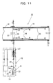
- Fig. 11 is a reactor in accordance with another embodiment.
- a reactor 30 is comprised of an outer tube 42 set coaxially and closely with an exhaust gas introducing line 41, and injectors 44, 46, and 48 set at proper length and position, and said injectors 44, 46, and 48 are supplied with OH radicals or an OH radical initiators from the OH radical supplier 12.
- Fig. 12 is an external view showing an example of an injector.
- the injector 49 shown in Fig. 12(a) is provided with a single blowout hole 54 at a tip side, and an injector 55 shown in Fig. 12(b) is provided with blowout holes 51, 52, 53, and 54 at proper positions, and the sizes of blowout holes are appropriately varied with the conductances of injectors taken into consideration.
- the blowout holes are set at one side of the injector, but they may be set at both sides.
- Such the injector is set at the center of the reactor, and supplies OH radicals or OH radical initiators.
- injectors may be pipes of stainless steel or quartz, but stainless steel is preferred, because of higher decrease ratio of NO and SO 2 .
- injectors it is easy to adjust the positions of blowout holes of injectors in a reactor and the supply quantity so that efficient desulfurization and denitration are possible depending upon the scale of exhaust gas and exhaust gas treating apparatus.
- the OH radical supplier 12 shown in Fig. 11 is to supply HNO 3 vapor or HNO 3 vapor and steam, but it may be an OH radical supplier to supply HNO 3 droplets.
- the injector is changed to spray nozzle, which introduces HNO 3 droplets into the reactor.
- Fig. 13 is an outline of a reactor in which HNO 3 droplets are sprayed.
- the reactor 50 has an outer tube 42 set in the direction vertical to the exhaust gas introducing line 41, a HNO 3 recovery apparatus 62 is provided at the exhaust gas introducing inlet side of said outer tube 42, and a recycling bath 58 of HNO 3 as an OH radical initiator is provided.
- shower pipes 56 and 56 are provided at appropriate positions of the outer tube 42 of the reactor 50, and from said shower pipes 56 and 56, an OH radical initiator is supplied by spraying.
- 59 in Fig. 13 illustrates the mist of OH radical initiators.
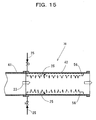
- Fig. 15 is of a horizontal type reactor 70, and shower pipes 56 and 56 are provided along an outer tube wall.
- the reactor described above may be either vertical or horizontal type.
- OH radicals supplied from the OH radical supplier or the OH radical generated from pyrolysis of an OH radical initiator acts as an initiator of the above-mentioned chain reaction to simultaneously oxidize SO 2 and NO in exhaust gas, and SO 3 and NO 2 are exhausted.
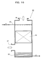
- Fig. 16 shows an example of a sulfuric acid recovery apparatus.
- the sulfuric acid recovery apparatus is a scrubber 80, provided with a bath 82, a packed tub 84, and a shower pipe 86 to spray absorbent, and the cooled exhaust gas containing SO 3 gas is introduced from a gas inlet 87, and exhausted from a gas outlet 88.
- the absorbent is water in small quantity, and water and SO 3 gas contact in the packed tube 84 to form sulfuric acid to be stored and recovered in the bath 82.
- SO 3 can be recovered as sulfuric acid by scrubber with water as the absorbent. Since SO 3 can be easily converted to sulfuric acid even under extremely trace amount of water, it is useful as a byproduct.
- sulfuric acid may be recovered as gypsum with calcium carbonate added and reacted with it.
- the sprayed HNO 3 is recovered by the above-mentioned HNO 3 recovery apparatus. Or, after SO 3 is recovered by an electric dust collector, NO 2 may be absorbed by a scrubber to be recovered as HNO 3 , supplied to the above-mentioned HNO 3 recovery apparatus and reused.
- the present invention is by no way limited to the above-mentioned embodiments, but various modification is possible within the range of the invention described in Claims, and needless to say that it is also included in the present invention.
- the reactor to blow in OH and OH radicals at multi-steps as explained in the above-mentioned embodiments may of course be properly designed, manufactured, and applied so as to be attached to various combustion apparatuses depending upon the flow rate of exhaust gas and SO 2 and NO gas concentrations to be desulfurized and denitrated.
- said apparatus for simultaneous dry desulfurization and denitration is such that the supplied OH radicals act as initiators to induce chain reaction, simultaneously oxidize SO 2 and NO in exhaust gas, and exhaust them as SO 3 and NO 2 , it can treat exhaust gas by dry method without using catalyst or others, as well as has the effect of high efficiency and low cost.
- the apparatus for simultaneous dry desulfurization and denitration provided with either or both of a sulfuric acid or HNO 3 recovery apparatuses has the effect capable of recovery of oxidized SO 3 and NO 2 as sulfuric acid and HNO 3 , and further an OH radical initiator as HNO 3 , in case that HNO 3 is used as the OH radical initiator.
Landscapes
- Engineering & Computer Science (AREA)
- Chemical & Material Sciences (AREA)
- Health & Medical Sciences (AREA)
- Biomedical Technology (AREA)
- Environmental & Geological Engineering (AREA)
- Analytical Chemistry (AREA)
- General Chemical & Material Sciences (AREA)
- Oil, Petroleum & Natural Gas (AREA)
- Chemical Kinetics & Catalysis (AREA)
- Treating Waste Gases (AREA)
Abstract
Description
HOSO2 formed here reacts with O2 in exhaust gas to form HO2 and SO3 (Refer to chemical reaction equation (R2)). In this case, since O2 concentration in exhaust gas is much higher than any other radical species, the reaction rate of (R2) is higher than the reactions of other HOSO2 with radical species, like OH + HOSO2, O + HOSO2, or H + HOSO2.
From these, the sum up of chemical reaction equations (R1) - (R3) becomes to be,
Fig. 3 is a graph showing the calculated values of mole fraction of sulfur compounds between 400 and 1000K. Its ordinate is mole fraction of sulfur compounds, and abscissa is temperature (K). It is seen from this that SO3 is more stable than H2SO4 and SO2 at 600 - 850K, and especially, its mole fraction reaches the maximum value at 650 - 800K. Therefore, it is conceivable that SO2 is easily oxidized at 650 - 800K.
Fig. 9 is a drawing showing the system structure of a dry process apparatus for simultaneous desulfurization and denitration in accordance with the present invention. Referring to Fig. 9, an apparatus for simultaneous dry desulfurization and
Here, multi-step reaction may be designed to proceed by further separating the
The OH
When the exhaust gas of 600 - 800 °C is introduced into such a reactor, OH radicals supplied from the OH radical supplier or the OH radical generated from pyrolysis of an OH radical initiator acts as an initiator of the above-mentioned chain reaction to simultaneously oxidize SO2 and NO in exhaust gas, and SO3 and NO2 are exhausted.
Fig. 16 shows an example of a sulfuric acid recovery apparatus. The sulfuric acid recovery apparatus is a
Also, the apparatus for simultaneous dry desulfurization and denitration provided with either or both of a sulfuric acid or HNO3 recovery apparatuses has the effect capable of recovery of oxidized SO3 and NO2 as sulfuric acid and HNO3, and further an OH radical initiator as HNO3, in case that HNO3 is used as the OH radical initiator.
Claims (16)
- An apparatus for simultaneous dry desulfurization and denitration characterized in that,
in an apparatus for dry exhaust gas treatment to treat exhaust gas of high temperature, a reactor and an OH radical supplier are comprised, either of OH radicals and an OH radical initiator is supplied to the reactor into which the above-mentioned exhaust gas is introduced, and either or both of the sulfur and the nitrogen compounds in exhaust gas are simultaneously oxidized to treat exhaust gas. - The apparatus for simultaneous dry desulfurization and denitration as set forth in claim 1, characterized in that said reactor is provided coaxially with an inner and an outer tubes separated by a space, and said inner tube is provided with a radical supplying inlet to supply OH radicals and an OH radical initiator.
- The apparatus for simultaneous dry desulfurization and denitration as set forth in claim 2, characterized in that said inner tube is provided with said radical supplying inlets at multi-steps at pre-designed intervals, thereby capable of multi-step blowing-in.
- The apparatus for simultaneous dry desulfurization and denitration as set forth in claim 1, characterized in that said reactor is provided with injectors to supply OH radicals and an OH radical initiator.
- The apparatus for simultaneous dry desulfurization and denitration as set forth in claim 4, characterized in that said injectors are provided as a plurality with different lengths, thereby capable of multi-step blowing-in.
- The apparatus for simultaneous dry desulfurization and denitration as set forth in claim 1, characterized in that said reactor is provided with a shower pipe and/or a spray nozzle to supply either OH radicals or an OH radical initiator.
- The apparatus for simultaneous dry desulfurization and denitration as set forth in any one of claims 1 - 6, characterized in that said reactor is either vertical or horizontal type.
- The apparatus for simultaneous dry desulfurization and denitration as set forth in any one of claims 1 - 7, characterized in that said OH radical supplier is provided with a radical generation source and a gas supplying system.
- The apparatus for simultaneous dry desulfurization and denitration as set forth in any one of claims 1 - 8, characterized in that said OH radical initiator is nitric acid.
- The apparatus for simultaneous dry desulfurization and denitration as set forth in any one of claims 1 - 8, characterized in that said OH radicals are generated from pyrolysis of nitric acid.
- The apparatus for simultaneous dry desulfurization and denitration as set forth in any one of claims 1 - 10, characterized in that said sulfur compound in exhaust gas is sulfur dioxide, and said nitrogen compound in exhaust gas is nitrogen monoxide, and said sulfur dioxide and said nitrogen monoxide are simultaneously oxidized with either said OH radical or said OH radical generated from an OH radical initiator as an initiator.
- The apparatus for simultaneous dry desulfurization and denitration as set forth in any one of claims 1 - 11, characterized in that said oxides generated from said simultaneous oxidation are sulfur trioxide and nitrogen dioxide.
- The apparatus for simultaneous dry desulfurization and denitration as set forth in any of claims 1 - 12, characterized in that said apparatus for simultaneous dry desulfurization and denitration is provided with a sulfuric acid recovery apparatus to recover sulfur trioxide generated from oxidation treating of exhaust gas as sulfuric acid and gypsum, or both.
- The apparatus for simultaneous dry desulfurization and denitration as set forth in any one of claims 1 - 12, characterized in that said apparatus for simultaneous dry desulfurization and denitration is provided with a nitric acid recovery apparatus to recover nitrogen dioxide generated from oxidation treating of exhaust gas as nitric acid.
- The apparatus for simultaneous dry desulfurization and denitration as set forth in any one of claims 1 - 14, characterized in that said apparatus for simultaneous dry desulfurization and denitration is provided with a nitric acid recovery apparatus to recover an OH radical supplier as nitric acid.
- The apparatus for simultaneous dry desulfurization and denitration as set forth in claim 15, characterized in that said recovered nitric acid is reused by recycling as an OH radical supplier.
Applications Claiming Priority (3)
| Application Number | Priority Date | Filing Date | Title |
|---|---|---|---|
| JP2003054900A JP4446269B2 (en) | 2003-02-28 | 2003-02-28 | Dry simultaneous desulfurization denitration equipment |
| JP2003054900 | 2003-02-28 | ||
| PCT/JP2003/017025 WO2004076032A1 (en) | 2003-02-28 | 2003-12-26 | Apparatus for simultaneous dry desulfurization/denitrification |
Publications (3)
| Publication Number | Publication Date |
|---|---|
| EP1600203A1 true EP1600203A1 (en) | 2005-11-30 |
| EP1600203A4 EP1600203A4 (en) | 2010-03-17 |
| EP1600203B1 EP1600203B1 (en) | 2014-09-24 |
Family
ID=32923478
Family Applications (1)
| Application Number | Title | Priority Date | Filing Date |
|---|---|---|---|
| EP03786375.0A Expired - Lifetime EP1600203B1 (en) | 2003-02-28 | 2003-12-26 | Apparatus for simultaneous dry desulfurization/denitrification |
Country Status (5)
| Country | Link |
|---|---|
| US (1) | US7455819B2 (en) |
| EP (1) | EP1600203B1 (en) |
| JP (1) | JP4446269B2 (en) |
| CN (1) | CN100396361C (en) |
| WO (1) | WO2004076032A1 (en) |
Families Citing this family (7)
| Publication number | Priority date | Publication date | Assignee | Title |
|---|---|---|---|---|
| CN101171070B (en) * | 2005-05-06 | 2012-10-17 | 国立大学法人岐阜大学 | Dry simultaneous desulfurization and denitrification device for waste gas |
| JP5093205B2 (en) * | 2009-09-30 | 2012-12-12 | 株式会社日立製作所 | Carbon dioxide recovery type power generation system |
| CN101961596A (en) * | 2010-07-19 | 2011-02-02 | 大连海事大学 | Oxidation sweetening and denitration method for hydroxyl radical of oxygen active particles injected in flue duct |
| CN104324610B (en) * | 2014-10-19 | 2016-07-06 | 陕西蔚蓝节能环境科技集团有限责任公司 | A kind of desulfurization denitration method and device |
| CN106422722A (en) * | 2016-10-12 | 2017-02-22 | 广东佳德环保科技有限公司 | Sintering flue gas denitration method adopting oxidation method |
| CN111001279B (en) * | 2019-12-26 | 2021-08-24 | 佛山科学技术学院 | A kind of high-efficiency dry denitrification agent and its preparation method and evaluation method of denitration effect |
| CN115253671A (en) * | 2022-08-13 | 2022-11-01 | 嘉兴复翼环保科技有限公司 | NO capable of assisting power by utilizing 2 Method for realizing SCR (selective catalytic reduction) efficient denitration by using generated additive |
Family Cites Families (12)
| Publication number | Priority date | Publication date | Assignee | Title |
|---|---|---|---|---|
| JPH05228330A (en) | 1991-08-26 | 1993-09-07 | Sumitomo Heavy Ind Ltd | Dry treatment of waste gas |
| JPH07323212A (en) | 1994-05-30 | 1995-12-12 | Tsuyako Nemoto | Waste incineration method and device |
| US5670122A (en) * | 1994-09-23 | 1997-09-23 | Energy And Environmental Research Corporation | Methods for removing air pollutants from combustion flue gas |
| JPH08243340A (en) | 1995-03-13 | 1996-09-24 | Mitsui Eng & Shipbuild Co Ltd | Exhaust gas treatment device and method |
| JPH10202049A (en) | 1997-01-27 | 1998-08-04 | Ishikawajima Harima Heavy Ind Co Ltd | Flue gas desulfurization equipment |
| JPH10225613A (en) | 1997-02-14 | 1998-08-25 | Ishikawajima Harima Heavy Ind Co Ltd | Ozone deodorizer |
| JP4066468B2 (en) | 1997-02-17 | 2008-03-26 | 株式会社Ihi | Air ozone mixer and ozone fog generator |
| JPH1182977A (en) | 1997-09-05 | 1999-03-26 | Kyoueisha:Kk | Method and equipment for decomposing freon |
| JP2001011041A (en) | 1999-06-29 | 2001-01-16 | Lion Corp | Method and apparatus for treating sulfur trioxide-containing gas at non-stationary state in sulfonation / sulfation |
| JP2001120943A (en) | 1999-10-25 | 2001-05-08 | Kazuyuki Takahata | Method and device for deodorizing waste gas |
| GB0020287D0 (en) * | 2000-08-17 | 2000-10-04 | Aea Technology Plc | The catalytic treatment of gases |
| JP3711490B2 (en) | 2001-06-01 | 2005-11-02 | 独立行政法人科学技術振興機構 | Method and apparatus for oxidizing SO2 in exhaust gas using HO2 radical as OH generating reactive species in radical chain reaction of SO2 oxidation |
-
2003
- 2003-02-28 JP JP2003054900A patent/JP4446269B2/en not_active Expired - Fee Related
- 2003-12-26 CN CNB2003801100115A patent/CN100396361C/en not_active Expired - Fee Related
- 2003-12-26 WO PCT/JP2003/017025 patent/WO2004076032A1/en not_active Ceased
- 2003-12-26 US US10/547,085 patent/US7455819B2/en not_active Expired - Fee Related
- 2003-12-26 EP EP03786375.0A patent/EP1600203B1/en not_active Expired - Lifetime
Non-Patent Citations (2)
| Title |
|---|
| No further relevant documents disclosed * |
| See also references of WO2004076032A1 * |
Also Published As
| Publication number | Publication date |
|---|---|
| EP1600203A4 (en) | 2010-03-17 |
| US7455819B2 (en) | 2008-11-25 |
| EP1600203B1 (en) | 2014-09-24 |
| CN100396361C (en) | 2008-06-25 |
| JP2004261718A (en) | 2004-09-24 |
| CN1756585A (en) | 2006-04-05 |
| US20060147356A1 (en) | 2006-07-06 |
| JP4446269B2 (en) | 2010-04-07 |
| WO2004076032A1 (en) | 2004-09-10 |
Similar Documents
| Publication | Publication Date | Title |
|---|---|---|
| CN1326767C (en) | Nox, Hg, and SO2 removal using ammonia | |
| EP0962247B1 (en) | Removal of NOx and SOx emissions from gaseous effluents | |
| US6991771B2 (en) | NOx, Hg, and SO2 removal using ammonia | |
| JP5455907B2 (en) | Exhaust gas purification method | |
| EP2719440A1 (en) | Method for removing contaminants from exhaust gases by adding ozone | |
| US9764281B2 (en) | Process for the removal of contaminants from flue gas streams | |
| KR101094672B1 (en) | Nitrogen oxide treatment method and treatment apparatus using ozone and catalytic hybrid system | |
| JP2002301335A (en) | Apparatus and method for desulfurization | |
| EP1600203B1 (en) | Apparatus for simultaneous dry desulfurization/denitrification | |
| KR101617691B1 (en) | Device for purifying exhuasted gas from chemical vapor deposition | |
| KR101097240B1 (en) | Exhaust gas treatment method and apparatus | |
| EP0933516B1 (en) | Gasification power generation process and equipment | |
| EP3012011A1 (en) | Method and apparatus for partial removal of contaminants from process gas stream | |
| KR100818309B1 (en) | Method and apparatus for removing nitrogen oxide using horizontal wet reactor | |
| KR102407755B1 (en) | The apparatus of multi-stage scrubber exhaust gas treatment and the method thereof | |
| KR20210120195A (en) | Duct structure | |
| KR101669551B1 (en) | Apparatus catalyzing decomposion of hydrogen peroxide thereof method | |
| CN114210187A (en) | Method for removing nitrogen oxides from exhaust gases and injection device | |
| KR20120118295A (en) | Method of removing sulfur oxides, elemental mercury, and nitrogen oxides in the exhaust gas | |
| HK1078303B (en) | Nox, hg, and so2 removal using ammonia | |
| KR19990008963A (en) | Exhaust Gas Treatment Method for Diesel Engine and Appropriate Device | |
| ITCA940007U1 (en) | PROCESS OF DESULPHURATION (99%) AND DENITRIFICATION (50%) OF THE GASES CONTAINING SULFUR DIOXIDE, NITROGEN OXIDES, CARBON DIOXIDE AND | |
| KR20110075307A (en) | How to remove elemental mercury in flue gas |
Legal Events
| Date | Code | Title | Description |
|---|---|---|---|
| PUAI | Public reference made under article 153(3) epc to a published international application that has entered the european phase |
Free format text: ORIGINAL CODE: 0009012 |
|
| 17P | Request for examination filed |
Effective date: 20050829 |
|
| AK | Designated contracting states |
Kind code of ref document: A1 Designated state(s): AT BE BG CH CY CZ DE DK EE ES FI FR GB GR HU IE IT LI LU MC NL PT RO SE SI SK TR |
|
| AX | Request for extension of the european patent |
Extension state: AL LT LV MK |
|
| DAX | Request for extension of the european patent (deleted) | ||
| RBV | Designated contracting states (corrected) |
Designated state(s): DE |
|
| RAP1 | Party data changed (applicant data changed or rights of an application transferred) |
Owner name: JAPAN SCIENCE AND TECHNOLOGY AGENCY |
|
| A4 | Supplementary search report drawn up and despatched |
Effective date: 20100216 |
|
| 17Q | First examination report despatched |
Effective date: 20110512 |
|
| GRAP | Despatch of communication of intention to grant a patent |
Free format text: ORIGINAL CODE: EPIDOSNIGR1 |
|
| GRAC | Information related to communication of intention to grant a patent modified |
Free format text: ORIGINAL CODE: EPIDOSCIGR1 |
|
| GRAJ | Information related to disapproval of communication of intention to grant by the applicant or resumption of examination proceedings by the epo deleted |
Free format text: ORIGINAL CODE: EPIDOSDIGR1 |
|
| GRAP | Despatch of communication of intention to grant a patent |
Free format text: ORIGINAL CODE: EPIDOSNIGR1 |
|
| INTG | Intention to grant announced |
Effective date: 20140415 |
|
| INTG | Intention to grant announced |
Effective date: 20140415 |
|
| GRAS | Grant fee paid |
Free format text: ORIGINAL CODE: EPIDOSNIGR3 |
|
| GRAA | (expected) grant |
Free format text: ORIGINAL CODE: 0009210 |
|
| AK | Designated contracting states |
Kind code of ref document: B1 Designated state(s): DE |
|
| REG | Reference to a national code |
Ref country code: DE Ref legal event code: R096 Ref document number: 60346788 Country of ref document: DE Effective date: 20141106 |
|
| PGFP | Annual fee paid to national office [announced via postgrant information from national office to epo] |
Ref country code: DE Payment date: 20150227 Year of fee payment: 12 |
|
| REG | Reference to a national code |
Ref country code: DE Ref legal event code: R097 Ref document number: 60346788 Country of ref document: DE |
|
| PLBE | No opposition filed within time limit |
Free format text: ORIGINAL CODE: 0009261 |
|
| STAA | Information on the status of an ep patent application or granted ep patent |
Free format text: STATUS: NO OPPOSITION FILED WITHIN TIME LIMIT |
|
| 26N | No opposition filed |
Effective date: 20150625 |
|
| REG | Reference to a national code |
Ref country code: DE Ref legal event code: R119 Ref document number: 60346788 Country of ref document: DE |
|
| PG25 | Lapsed in a contracting state [announced via postgrant information from national office to epo] |
Ref country code: DE Free format text: LAPSE BECAUSE OF NON-PAYMENT OF DUE FEES Effective date: 20160701 |