EP1599416B1 - Process for producing chlorine dioxide - Google Patents
Process for producing chlorine dioxide Download PDFInfo
- Publication number
- EP1599416B1 EP1599416B1 EP04716399.3A EP04716399A EP1599416B1 EP 1599416 B1 EP1599416 B1 EP 1599416B1 EP 04716399 A EP04716399 A EP 04716399A EP 1599416 B1 EP1599416 B1 EP 1599416B1
- Authority
- EP
- European Patent Office
- Prior art keywords
- reactor
- sulfuric acid
- feeding
- chlorine dioxide
- product stream
- Prior art date
- Legal status (The legal status is an assumption and is not a legal conclusion. Google has not performed a legal analysis and makes no representation as to the accuracy of the status listed.)
- Expired - Lifetime
Links
Images

Classifications
-
- B—PERFORMING OPERATIONS; TRANSPORTING
- B01—PHYSICAL OR CHEMICAL PROCESSES OR APPARATUS IN GENERAL
- B01J—CHEMICAL OR PHYSICAL PROCESSES, e.g. CATALYSIS OR COLLOID CHEMISTRY; THEIR RELEVANT APPARATUS
- B01J4/00—Feed or outlet devices; Feed or outlet control devices
- B01J4/001—Feed or outlet devices as such, e.g. feeding tubes
- B01J4/002—Nozzle-type elements
-
- C—CHEMISTRY; METALLURGY
- C01—INORGANIC CHEMISTRY
- C01B—NON-METALLIC ELEMENTS; COMPOUNDS THEREOF; METALLOIDS OR COMPOUNDS THEREOF NOT COVERED BY SUBCLASS C01C
- C01B11/00—Oxides or oxyacids of halogens; Salts thereof
- C01B11/02—Oxides of chlorine
-
- B—PERFORMING OPERATIONS; TRANSPORTING
- B01—PHYSICAL OR CHEMICAL PROCESSES OR APPARATUS IN GENERAL
- B01F—MIXING, e.g. DISSOLVING, EMULSIFYING OR DISPERSING
- B01F25/00—Flow mixers; Mixers for falling materials, e.g. solid particles
- B01F25/20—Jet mixers, i.e. mixers using high-speed fluid streams
- B01F25/23—Mixing by intersecting jets
-
- B—PERFORMING OPERATIONS; TRANSPORTING
- B01—PHYSICAL OR CHEMICAL PROCESSES OR APPARATUS IN GENERAL
- B01F—MIXING, e.g. DISSOLVING, EMULSIFYING OR DISPERSING
- B01F25/00—Flow mixers; Mixers for falling materials, e.g. solid particles
- B01F25/30—Injector mixers
- B01F25/31—Injector mixers in conduits or tubes through which the main component flows
- B01F25/312—Injector mixers in conduits or tubes through which the main component flows with Venturi elements; Details thereof
- B01F25/3121—Injector mixers in conduits or tubes through which the main component flows with Venturi elements; Details thereof with additional mixing means other than injector mixers, e.g. screens, baffles or rotating elements
-
- B—PERFORMING OPERATIONS; TRANSPORTING
- B01—PHYSICAL OR CHEMICAL PROCESSES OR APPARATUS IN GENERAL
- B01F—MIXING, e.g. DISSOLVING, EMULSIFYING OR DISPERSING
- B01F25/00—Flow mixers; Mixers for falling materials, e.g. solid particles
- B01F25/30—Injector mixers
- B01F25/31—Injector mixers in conduits or tubes through which the main component flows
- B01F25/312—Injector mixers in conduits or tubes through which the main component flows with Venturi elements; Details thereof
- B01F25/3124—Injector mixers in conduits or tubes through which the main component flows with Venturi elements; Details thereof characterised by the place of introduction of the main flow
- B01F25/31243—Eductor or eductor-type venturi, i.e. the main flow being injected through the venturi with high speed in the form of a jet
-
- B—PERFORMING OPERATIONS; TRANSPORTING
- B01—PHYSICAL OR CHEMICAL PROCESSES OR APPARATUS IN GENERAL
- B01J—CHEMICAL OR PHYSICAL PROCESSES, e.g. CATALYSIS OR COLLOID CHEMISTRY; THEIR RELEVANT APPARATUS
- B01J14/00—Chemical processes in general for reacting liquids with liquids; Apparatus specially adapted therefor
-
- B—PERFORMING OPERATIONS; TRANSPORTING
- B01—PHYSICAL OR CHEMICAL PROCESSES OR APPARATUS IN GENERAL
- B01J—CHEMICAL OR PHYSICAL PROCESSES, e.g. CATALYSIS OR COLLOID CHEMISTRY; THEIR RELEVANT APPARATUS
- B01J19/00—Chemical, physical or physico-chemical processes in general; Their relevant apparatus
- B01J19/24—Stationary reactors without moving elements inside
- B01J19/2415—Tubular reactors
-
- B—PERFORMING OPERATIONS; TRANSPORTING
- B01—PHYSICAL OR CHEMICAL PROCESSES OR APPARATUS IN GENERAL
- B01J—CHEMICAL OR PHYSICAL PROCESSES, e.g. CATALYSIS OR COLLOID CHEMISTRY; THEIR RELEVANT APPARATUS
- B01J4/00—Feed or outlet devices; Feed or outlet control devices
- B01J4/001—Feed or outlet devices as such, e.g. feeding tubes
-
- C—CHEMISTRY; METALLURGY
- C01—INORGANIC CHEMISTRY
- C01B—NON-METALLIC ELEMENTS; COMPOUNDS THEREOF; METALLOIDS OR COMPOUNDS THEREOF NOT COVERED BY SUBCLASS C01C
- C01B11/00—Oxides or oxyacids of halogens; Salts thereof
- C01B11/02—Oxides of chlorine
- C01B11/022—Chlorine dioxide (ClO2)
- C01B11/023—Preparation from chlorites or chlorates
- C01B11/026—Preparation from chlorites or chlorates from chlorate ions in the presence of a peroxidic compound, e.g. hydrogen peroxide, ozone, peroxysulfates
Definitions
- the present invention relates to a process and an apparatus for producing chlorine dioxide from a mineral acid, alkali metal chlorate and hydrogen peroxide.
- Chlorine dioxide is used in various applications such as pulp bleaching, fat bleaching, water purification and removal of organic materials from industrial wastes. Since chlorine dioxide is not storage stable, it must be produced on-site.
- Chlorine dioxide can be produced by reacting alkali metal chlorate and a mineral acid, preferably sulfuric acid, with a reducing agent in an aqueous reaction medium.
- a mineral acid preferably sulfuric acid
- a reducing agent preferably sulfuric acid
- Such processes are described in US patents 2833624 , 4534952 , 5895638 , WO 00/76916 , and WO 03/000586 .
- a similar process is described in US Patent Application Pub. No. 2003/0031621 , teaching that the reactants should be injected into a spherical reaction chamber.
- the optimal way of operating the process is to use a substantially vertical reactor in which a disk or the like provided with apertures is arranged, wherein a premixed solution of alkali metal chlorate and hydrogen peroxide is fed above the disk, while sulfuric acid is fed below the disk and brought to flow through the apertures and then mix with the alkali metal chlorate and the hydrogen peroxide.
- a substantially vertical reactor in which a disk or the like provided with apertures is arranged, wherein a premixed solution of alkali metal chlorate and hydrogen peroxide is fed above the disk, while sulfuric acid is fed below the disk and brought to flow through the apertures and then mix with the alkali metal chlorate and the hydrogen peroxide.
- sulfuric acid of high concentration preferably above about 90 wt%, since this sulfuric acid is both less corrosive and more readily available on the market than more diluted grades.
- chlorine dioxide production is very low, it has been found that if sulfuric acid of high concentration is used it is difficult to achieve stable operation without frequent decomposition of chlorine dioxide.
- the product stream withdrawn from the reactor is brought to an eductor connected to an outlet of the reactor, creating a suction force bringing the product stream, including any liquid, foam and gas therein, to flow into the eductor and mix with motive water to form a diluted solution containing chlorine dioxide.
- eductor Any suitable type of eductor can be used, such as those described in WO 03/000586 .
- the dilution of the sulfuric acid can be achieved by any means where it is blended with water, of which a static mixer is particularly preferred. If the temperature of the sulfuric acid after dilution exceed about 100°C, cooling is necessary, which can be achieved in any conventional manner for removing thermal energy. It has been found particularly advantageous to use a heat exchanger in which a slip stream of motive water for the eductor serves as a cooling medium. Preferably from about 1 to about 6 kg H 2 SO 4 , most preferably from about 2 to about 4 kg H 2 SO 4 is fed per kg ClO 2 produced.
- the reactor is a substantially tubular through-flow vessel or pipe.
- the first and second feeding nozzles are then suitably situated close to one end of the reactor while the product stream is withdrawn at the other end.
- the first and second feeding nozzles are situated at opposite sides of and directed towards the centre line along the reactor, i.e. towards the centre of the cross-section of the reactor.
- further feeding nozzles for sulfuric acid and a solution of alkali metal chlorate and hydrogen peroxide.
- the reactor may also be provided with nozzles for flushing and draining during maintenance.
- the reactor is arranged substantially vertically with the first and second feeding nozzles preferably situated close to the bottom thereof so the main flow-direction through, the reactor is upwards and the product stream is withdrawn at the top thereof.
- the length (in the main flow direction) of the reactor used is preferably from about 50 to about 800 mm, most preferably from about 200 to about 650 mm. It has been found favourable to use a substantially tubular reactor with an inner diameter from about 25 to about 300 mm, preferably from about 70 to about 200 mm. It is particularly favourable to use a substantially tubular reactor having a preferred ratio of the length to the inner diameter from about 12:1 to about 1:1, most preferably from about 8:1 to about 4:1. A suitable average residence time in the reactor is in most cases from about 1 to about 1000 seconds, preferably from about 2 to about 40 seconds.
- the aqueous solution comprising alkali metal chlorate and hydrogen peroxide fed through the second feeding nozzle may have a composition as described in WO 00/76916 , which hereby is incorporated by reference.
- a composition may be an aqueous solution comprising from about 1 to about 6.5 moles/liter, preferably from about 3 to about 6 moles/liter of alkali metal chlorate, from about 1 to about 7 moles/liter, preferably from about 3 to about 5 moles/liter of hydrogen peroxide and at least one of a protective colloid, a radical scavenger or a phosphonic acid based complexing agent, wherein the pH of the aqueous solution suitably is from about 0.5 to about 4, preferably from about 1 to about 3.5, most preferably from about 1.5 to about 3.
- At least one phosphonic acid based complexing agent is present, preferably in an amount from about 0.1 to about 5 mmoles/liter, most preferably from about 0.5 to about 3 mmoles/liter.
- a protective colloid is present, its concentration is preferably from about 0.001 to about 0.5 moles/liter, most preferably from about 0.02 to about 0.05 moles/liter.
- a radical scavenger is present, its concentration is preferably from about 0.01 to about 1 moles/liter, most preferably from about 0.02 to about 0.2 moles/liter.
- compositions comprise at least one phosphonic acid based complexing agent selected from the group consisting of 1-hydroxyethylidene-1,1-diphosphonic acid, 1-aminoethane-1,1-diphosphonic acid, aminotri (methylenephosphonic acid), ethylene diamine tetra (methylenephosphonic acid), hexamethylene diamine tetra (methylenephosphonic acid), diethylenetriamine penta (methylenephosphonic acid), diethylenetriamine hexa (methylenephosphonic acid), 1-aminoalkane-1,1-diphosphonic acids (such as morpholinomethane diphosphonic acid, N,N-dimethyl aminodimethyl diphosphonic acid, aminomethyl diphosphonic acid), reaction products and salts thereof, preferably sodium salts.
- phosphonic acid based complexing agent selected from the group consisting of 1-hydroxyethylidene-1,1-diphosphonic acid, 1-aminoethane-1,1-diphosphonic acid, aminotri (methylenephosphonic
- Useful protective colloids include tin compounds, such as alkali metal stannate, particularly sodium stannate (Na 2 (Sn(OH) 6 ).
- Useful radical scavengers include pyridine carboxylic acids, such as 2,6-pyridine dicarboxylic acid.
- the amount of chloride ions is below about 300 mmoles/liter, preferably below about 50 mmoles/liter, more preferably below about 5 mmoles/liter, most preferably below about 0.5 mmoles/liter.
- alkali metal chlorate, mineral acid and hydrogen peroxide results in formation of a product stream in the reactor, normally comprising both liquid and foam and containing chlorine dioxide, oxygen, alkali metal salt of the mineral acid and, in most cases, some remaining unreacted species from the feed chemicals such as alkali metal chlorate and mineral acid.
- Chlorine dioxide and oxygen may be present both as dissolved in the liquid and as gas bubbles. It has been found possible to achieve a conversion degree of chlorate to chlorine dioxide from about 75% to 100%, preferably from about 80 to 100%, most preferably from about 95 to 100%.
- the temperature in the reactor is suitably maintained below the boiling point of the reactants and the product stream at the prevailing pressure, preferably from about 20 to about 80°C, most preferably from about 30 to about 60°C.
- the pressure maintained within the reactor is suitably slightly subatmospheric, preferably from about 30 to about 100 kPa absolute, most preferably from about 65 to about 95 kPa absolute.
- the invention further relates to an apparatus suitable for producing chlorine dioxide according to the above described process.
- the apparatus comprises means for diluting sulfuric acid, preferably a static mixer, means for cooling the diluted sulfuric acid, preferably a heat exchanger, a reactor in which is arranged a first feeding nozzle for a mineral acid and a second feeding nozzle for an aqueous solution comprising alkali metal chlorate and hydrogen peroxide, wherein said first and second feeding nozzles are opposite to and directed against each other and the reactor further is provided with an outlet for a product stream containing chlorine dioxide.
- Fig. 1 is a schematic flow sheet of a preferred process of the invention
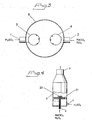
- Fig. 2 schematically shows a side section of a chlorine dioxide reactor of the invention
- Fig. 3 schematically shows a top section of the feeding nozzles for the reactor
- Fig. 4 schematically show a chlorine dioxide reactor of the prior art.
- sulfuric acid of high concentration e.g. above 90 wt%, and moderate temperature, e.g. from about 0 to about 50°C
- a sulfuric acid stream 11 with a concentration from 65 to 88 wt%, and, due to the heat produced by the dilution, generally a temperature from about 95 to about 115°C.
- the diluted sulfuric acid stream 11 is brought to a heat exchanger 12, in which it preferably is cooled to a to a temperature below about 95°C, most preferably from about 30 to about 65°C.
- the cooled sulfuric acid stream 1 is then fed to a vertical through-flow tubular reactor 5, to which also a pre-mixed aqueous solution of sodium chlorate and hydrogen peroxide is fed through feed line 2.
- the feed streams are mixed and reacted to form a product stream of liquid, foam and gas comprising chlorine dioxide, oxygen, sodium sulfate and some remaining sulfuric acid and sodium chlorate.
- An eductor 14 is supplied with motive water through feed line 15 and generates a subatmospheric pressure forcing the product stream out from the reactor 5 and into the eductor 14 where it is mixed with the motive water to form a diluted aqueous product solution.
- This diluted solution contains chlorine dioxide and the other component from the reactor 5 and is withdrawn as a final product.
- a slip stream 16 of the motive water 15 is used as cooling medium for the sulfuric acid in the heat exchanger 12.
- a practical way to provide sufficient driving force for the return 17 of the cooling water is to create a pressure drop, e.g. by the means of an orifice plate (not shown), in the motive water stream 15 between the lines 16 and 17.
- an insert 6 is arranged close to the bottom of the reactor 5 and provided with a first feeding nozzle 3 connected to the feed line 1 for sulfuric acid and a second feeding nozzle 4 connected to the feed line 2 for the sodium chlorate / hydrogen peroxide solution.
- the first and second feeding nozzles 3, 4 are arranged opposite to each other at substantially equal distance from the centre of the cross section of the reactor 5.
- Each nozzle 3, 4 preferably has a spray pattern from about 20 to about 180 degrees, most preferably from about 60 to about 135 degrees.
- the nozzles do not atomize the liquid into individual droplets.
- the sulfuric acid and the sodium chlorate / hydrogen peroxide solution are sprayed at each other towards the centre of the cross section of the reactor 5.
- the reaction generating chlorine dioxide starts and creates a product stream of liquid, foam and gas, which stream is withdrawn through the outlet 7 at the top of the reactor 5 and then brought to the eductor 14 ( Fig. 1 ).
- the process equipment including the reactor 5 and the eductor 14, is suitably made from materials resistant to hydrogen peroxide, sodium chlorate, sulfuric acid and chlorine dioxide.
- materials include, for example, glass, tantalum, titanium, fibreglass reinforced plastic, fluoro plastics like PVDF (polyvinylidene fluoride) CPVC (chlorinated polyvinyl chloride), PTFE (polytetrafluoro ethylene), PFA (perfluoro alkoxy polymer), ECTFE (ethylene chlorotrifluoro ethylene) or FEP (fluorinated ethylene propylene).
- PVDF polyvinylidene fluoride
- CPVC chlorinated polyvinyl chloride
- PTFE polytetrafluoro ethylene
- PFA perfluoro alkoxy polymer
- ECTFE ethylene chlorotrifluoro ethylene
- FEP fluorinated ethylene propylene
- fluoro plastics are sold under the trademarks Kynar ® , Tef
- Fig. 4 shows an arrangement of the prior art.
- the reactor 5 as such is identical to the one of Fig. 2 , but the means for feeding the chemicals are different.
- a distribution disk 21 provided with apertures is arranged in the lower part of the reactor 5, but above the inlet from the feed line 1 for sulfuric acid.
- the feed line 2 for the pre-mixed sodium chlorate and hydrogen peroxide solution ends in a distribution nozzle 20 arranged in the centre of the cross section of the reactor just above the distribution disk.
- the sodium chlorate and hydrogen peroxide solution is then sprayed over the cross section within the reactor 5, while the sulfuric acid flows upwards through the apertures in the distribution disk 21 and is mixed with the sodium chlorate and hydrogen peroxide above the distribution disk 21.
- the reaction generating chlorine dioxide starts and creates a product stream of liquid, foam and gas, which stream is withdrawn through the outlet 7 at the top of the reactor 5.
- this kind of arrangement has been found to give less stable operation than the arrangement of the invention.
- the 93 wt% sulfuric acid was diluted in the static mixer 10 to 78 wt% and cooled in the heat exchanger 12 to 30°C before feeding into the reactor 5.
- the opposing feeding nozzles 3, 4 had a spray pattern of 120 degrees and the tubular reactor 5 had a length of 610 mm and a diameter of 76 mm.
- the reactor 5 was maintained at a temperature of 50°C and a pressure of 50 kPa. Experiments were also made without cooling the diluted sulfuric acid, which then had a temperature of about 104°C when fed into the reactor 5. As a comparison, the process was also run with the same kind of reactor, but provided with feeding means for the sulfuric acid and the sodium chlorate / hydrogen peroxide solution as shown in Fig. 4 , i.e. a distribution disk 21 and a distribution nozzle 20.
Landscapes
- Chemical & Material Sciences (AREA)
- Organic Chemistry (AREA)
- Chemical Kinetics & Catalysis (AREA)
- Inorganic Chemistry (AREA)
- Life Sciences & Earth Sciences (AREA)
- General Life Sciences & Earth Sciences (AREA)
- Geology (AREA)
- Organic Low-Molecular-Weight Compounds And Preparation Thereof (AREA)
- Physical Or Chemical Processes And Apparatus (AREA)
- Agricultural Chemicals And Associated Chemicals (AREA)
- Pharmaceuticals Containing Other Organic And Inorganic Compounds (AREA)
- Electrolytic Production Of Non-Metals, Compounds, Apparatuses Therefor (AREA)
Description
- The present invention relates to a process and an apparatus for producing chlorine dioxide from a mineral acid, alkali metal chlorate and hydrogen peroxide.
- Chlorine dioxide is used in various applications such as pulp bleaching, fat bleaching, water purification and removal of organic materials from industrial wastes. Since chlorine dioxide is not storage stable, it must be produced on-site.
- Chlorine dioxide can be produced by reacting alkali metal chlorate and a mineral acid, preferably sulfuric acid, with a reducing agent in an aqueous reaction medium. For production in small-scale units, such as for water purification applications or small bleaching plants, it is favourable not to separate chlorine dioxide gas from the reaction medium but to recover a chlorine dioxide containing solution directly from the reactor, optionally after dilution with water. Such processes are described in
US patents 2833624 ,4534952 ,5895638 ,WO 00/76916 WO 03/000586 US Patent Application Pub. No. 2003/0031621 , teaching that the reactants should be injected into a spherical reaction chamber. - Experience from commercial operation has shown that the way of feeding and mixing the chemicals affects the efficiency of the process. It has until now been believed that the optimal way of operating the process is to use a substantially vertical reactor in which a disk or the like provided with apertures is arranged, wherein a premixed solution of alkali metal chlorate and hydrogen peroxide is fed above the disk, while sulfuric acid is fed below the disk and brought to flow through the apertures and then mix with the alkali metal chlorate and the hydrogen peroxide. Such an arrangement is described In
WO 03/000586 - It is desirable to use sulfuric acid of high concentration, preferably above about 90 wt%, since this sulfuric acid is both less corrosive and more readily available on the market than more diluted grades. However, unless the chlorine dioxide production is very low, it has been found that if sulfuric acid of high concentration is used it is difficult to achieve stable operation without frequent decomposition of chlorine dioxide.
- It is an object of the invention to provide a process for the production of chlorine dioxide that can be operated without substantial decomposition of chlorine dioxide.
- It is another object of the invention to provide a process for the production of chlorine dioxide in which sulfuric acid of high concentration can be used.
- It is still another object of the invention to provide an apparatus useful for the above purposes.
- It has surprisingly been found possible to meet these objects by providing a process for continuously producing chlorine dioxide comprising the steps of:
- diluting sulfuric acid of an initial concentration exceeding about 90 wt% with water, to a concentration from about 60 to about 90 wt%, preferably from about 65 to about 88 wt%;
- bringing the diluted sulfuric acid to a temperature below about 100°C, preferably to a temperature from about 5 to about 95°C, most preferably from about 30 to about 65°C; feeding to a reactor the diluted sulfuric acid having a temperature below about 100°C, preferably from about 5 to about 95°C, most preferably from about 30 to about 65°C, through a first feeding nozzle;
- feeding to said reactor an aqueous solution comprising alkali metal chlorate and hydrogen peroxide through a second feeding nozzle, wherein said first and second feeding nozzles are opposite to and directed against each other;
- reacting the alkall metal chlorate with the mineral acid and the hydrogen peroxide to form a product stream containing chlorine dioxide; and,
- withdrawing the product stream from the reactor, and wherein the reactor is as substantially tubular through-flow vessel or pipe.
- Preferably the product stream withdrawn from the reactor is brought to an eductor connected to an outlet of the reactor, creating a suction force bringing the product stream, including any liquid, foam and gas therein, to flow into the eductor and mix with motive water to form a diluted solution containing chlorine dioxide. Any suitable type of eductor can be used, such as those described in
WO 03/000586 - The dilution of the sulfuric acid can be achieved by any means where it is blended with water, of which a static mixer is particularly preferred. If the temperature of the sulfuric acid after dilution exceed about 100°C, cooling is necessary, which can be achieved in any conventional manner for removing thermal energy. It has been found particularly advantageous to use a heat exchanger in which a slip stream of motive water for the eductor serves as a cooling medium. Preferably from about 1 to about 6 kg H2SO4, most preferably from about 2 to about 4 kg H2SO4 is fed per kg ClO2 produced.
- The reactor is a substantially tubular through-flow vessel or pipe. The first and second feeding nozzles are then suitably situated close to one end of the reactor while the product stream is withdrawn at the other end. Preferably the first and second feeding nozzles are situated at opposite sides of and directed towards the centre line along the reactor, i.e. towards the centre of the cross-section of the reactor. Although not necessary, it is possible to use further feeding nozzles for sulfuric acid and a solution of alkali metal chlorate and hydrogen peroxide. The reactor may also be provided with nozzles for flushing and draining during maintenance. Most preferably the reactor is arranged substantially vertically with the first and second feeding nozzles preferably situated close to the bottom thereof so the main flow-direction through, the reactor is upwards and the product stream is withdrawn at the top thereof.
- The length (in the main flow direction) of the reactor used is preferably from about 50 to about 800 mm, most preferably from about 200 to about 650 mm. It has been found favourable to use a substantially tubular reactor with an inner diameter from about 25 to about 300 mm, preferably from about 70 to about 200 mm. It is particularly favourable to use a substantially tubular reactor having a preferred ratio of the length to the inner diameter from about 12:1 to about 1:1, most preferably from about 8:1 to about 4:1. A suitable average residence time in the reactor is in most cases from about 1 to about 1000 seconds, preferably from about 2 to about 40 seconds.
- The aqueous solution comprising alkali metal chlorate and hydrogen peroxide fed through the second feeding nozzle may have a composition as described in
WO 00/76916 - The reaction of alkali metal chlorate, mineral acid and hydrogen peroxide results in formation of a product stream in the reactor, normally comprising both liquid and foam and containing chlorine dioxide, oxygen, alkali metal salt of the mineral acid and, in most cases, some remaining unreacted species from the feed chemicals such as alkali metal chlorate and mineral acid. Chlorine dioxide and oxygen may be present both as dissolved in the liquid and as gas bubbles. It has been found possible to achieve a conversion degree of chlorate to chlorine dioxide from about 75% to 100%, preferably from about 80 to 100%, most preferably from about 95 to 100%.
- The temperature in the reactor is suitably maintained below the boiling point of the reactants and the product stream at the prevailing pressure, preferably from about 20 to about 80°C, most preferably from about 30 to about 60°C. The pressure maintained within the reactor is suitably slightly subatmospheric, preferably from about 30 to about 100 kPa absolute, most preferably from about 65 to about 95 kPa absolute.
- The invention further relates to an apparatus suitable for producing chlorine dioxide according to the above described process. The apparatus comprises means for diluting sulfuric acid, preferably a static mixer, means for cooling the diluted sulfuric acid, preferably a heat exchanger, a reactor in which is arranged a first feeding nozzle for a mineral acid and a second feeding nozzle for an aqueous solution comprising alkali metal chlorate and hydrogen peroxide, wherein said first and second feeding nozzles are opposite to and directed against each other and the reactor further is provided with an outlet for a product stream containing chlorine dioxide.
- Preferred embodiments of the apparatus are apparent from the above description of the process and the following description referring to the schematic drawings. The invention is, however, not limited to the embodiments shown in the drawings and encompasses many other variants within the scope of the claims.
-
Fig. 1 is a schematic flow sheet of a preferred process of the invention,Fig. 2 schematically shows a side section of a chlorine dioxide reactor of the invention,Fig. 3 schematically shows a top section of the feeding nozzles for the reactor, whileFig. 4 schematically show a chlorine dioxide reactor of the prior art. - Referring to
Fig. 1 , sulfuric acid of high concentration, e.g. above 90 wt%, and moderate temperature, e.g. from about 0 to about 50°C, is diluted with water in astatic mixer 10 to yield asulfuric acid stream 11 with a concentration from 65 to 88 wt%, and, due to the heat produced by the dilution, generally a temperature from about 95 to about 115°C. The dilutedsulfuric acid stream 11 is brought to aheat exchanger 12, in which it preferably is cooled to a to a temperature below about 95°C, most preferably from about 30 to about 65°C. The cooledsulfuric acid stream 1 is then fed to a vertical through-flowtubular reactor 5, to which also a pre-mixed aqueous solution of sodium chlorate and hydrogen peroxide is fed throughfeed line 2. In thereactor 5 the feed streams are mixed and reacted to form a product stream of liquid, foam and gas comprising chlorine dioxide, oxygen, sodium sulfate and some remaining sulfuric acid and sodium chlorate. Aneductor 14 is supplied with motive water throughfeed line 15 and generates a subatmospheric pressure forcing the product stream out from thereactor 5 and into theeductor 14 where it is mixed with the motive water to form a diluted aqueous product solution. This diluted solution contains chlorine dioxide and the other component from thereactor 5 and is withdrawn as a final product. Aslip stream 16 of themotive water 15 is used as cooling medium for the sulfuric acid in theheat exchanger 12. A practical way to provide sufficient driving force for thereturn 17 of the cooling water is to create a pressure drop, e.g. by the means of an orifice plate (not shown), in themotive water stream 15 between thelines - Referring to
Figs. 2 and3 , aninsert 6 is arranged close to the bottom of thereactor 5 and provided with afirst feeding nozzle 3 connected to thefeed line 1 for sulfuric acid and asecond feeding nozzle 4 connected to thefeed line 2 for the sodium chlorate / hydrogen peroxide solution. The first andsecond feeding nozzles reactor 5. Eachnozzle reactor 5. Upon mixture, the reaction generating chlorine dioxide starts and creates a product stream of liquid, foam and gas, which stream is withdrawn through theoutlet 7 at the top of thereactor 5 and then brought to the eductor 14 (Fig. 1 ). - The process equipment, including the
reactor 5 and theeductor 14, is suitably made from materials resistant to hydrogen peroxide, sodium chlorate, sulfuric acid and chlorine dioxide. Such materials include, for example, glass, tantalum, titanium, fibreglass reinforced plastic, fluoro plastics like PVDF (polyvinylidene fluoride) CPVC (chlorinated polyvinyl chloride), PTFE (polytetrafluoro ethylene), PFA (perfluoro alkoxy polymer), ECTFE (ethylene chlorotrifluoro ethylene) or FEP (fluorinated ethylene propylene). Alternatively, such materials may be used as a liner material to a structural material like steel or stainless steel. Suitable fluoro plastics are sold under the trademarks Kynar®, Teflon® or Halar®. -
Fig. 4 shows an arrangement of the prior art. Thereactor 5 as such is identical to the one ofFig. 2 , but the means for feeding the chemicals are different. Thus, instead of feeding nozzles opposite to each other, adistribution disk 21 provided with apertures is arranged in the lower part of thereactor 5, but above the inlet from thefeed line 1 for sulfuric acid. Thefeed line 2 for the pre-mixed sodium chlorate and hydrogen peroxide solution ends in adistribution nozzle 20 arranged in the centre of the cross section of the reactor just above the distribution disk. The sodium chlorate and hydrogen peroxide solution is then sprayed over the cross section within thereactor 5, while the sulfuric acid flows upwards through the apertures in thedistribution disk 21 and is mixed with the sodium chlorate and hydrogen peroxide above thedistribution disk 21. Upon mixture, the reaction generating chlorine dioxide starts and creates a product stream of liquid, foam and gas, which stream is withdrawn through theoutlet 7 at the top of thereactor 5. However, this kind of arrangement has been found to give less stable operation than the arrangement of the invention. - The invention is further illustrated through the following example. Unless otherwise stated, all parts and percentages refer to parts and percent by weight.
- Example: A process of the invention set up as described in
Figs. 1-3 was operated with 93 wt% sulfuric acid and an aqueous solution of 40 wt% sodium chlorate and 10 wt% hydrogen peroxide stabilized with a phosphonic acid based complexing agent (marketed as Purate®, Eka Chemicals Inc.). The 93 wt% sulfuric acid was diluted in thestatic mixer 10 to 78 wt% and cooled in theheat exchanger 12 to 30°C before feeding into thereactor 5. The opposingfeeding nozzles tubular reactor 5 had a length of 610 mm and a diameter of 76 mm. Thereactor 5 was maintained at a temperature of 50°C and a pressure of 50 kPa. Experiments were also made without cooling the diluted sulfuric acid, which then had a temperature of about 104°C when fed into thereactor 5. As a comparison, the process was also run with the same kind of reactor, but provided with feeding means for the sulfuric acid and the sodium chlorate / hydrogen peroxide solution as shown inFig. 4 , i.e. adistribution disk 21 and adistribution nozzle 20. The results appear in the table below:Feeding means Cooling (C) / Dilution (D) ClO2 Production (lb/hr) Stable Runs Without ClO2 Decompositions Opposing Nozzles C/D 35 (15.9 kg/hr) Yes Opposing Nozzles C/D 8 (3.6 kg/hr) Yes Opposing Nozzles D 35 (15.9 kg/hr) No Opposing Nozzles D 8 (3.6 kg/hr) No Distribution disk C/D 35 (15.9 kg/hr) No Distribution disk C/D 8 (3.6 kg/hr) No Distribution disk D 35 (15.9 kg/hr) No Distribution disk D 8 (3.6 kg/hr) No
Claims (10)
- A process for continuously producing chlorine dioxide comprising the steps of:diluting sulfuric acid of an initial concentration exceeding about 90 wt% with water to a concentration from about 60 to about 90 wt%;bringing the diluted sulfuric acid to a temperature below about 100°C;feeding to a reactor (5) the diluted sulfuric acid having a temperature below about 100°C through a first feeding nozzle (3);feeding to said reactor (5) an aqueous solution comprising alkali metal chlorate andhydrogen peroxide through a second feeding nozzle (4), wherein said first and second feeding nozzles (3, 4) are opposite to and directed against each other;reacting the alkali metal chlorate with the mineral acid and the hydrogen peroxide to form a product stream containing chlorine dioxide; and,withdrawing the product stream from the reactor (5), and wherein the reactor (5) is a substantially tubular through-flow vessel or pipe.
- A process as claimed in claim 1, wherein the product stream withdrawn from the reactor (5) is brought to an eductor (14) in which it is diluted with motive water to form an aqueous solution containing chlorine dioxide.
- A process as claimed in any one of claims 1-2, wherein the diluted sulfuric acid is brought to a temperature from about 5 to about 95°C.
- A process as claimed in any one of claims 1-3, wherein the sulfuric acid is diluted with water by means of a static mixer (10).
- A process as claimed in any one of claims 2-4, wherein the diluted sulfuric acid is cooled in a heat exchanger (12) with a slipstream of motive water for the eductor (14) as cooling medium.
- A process as claimed any one of claims 1-5, wherein first and second feeding nozzles (3, 4) are situated close to one end of the reactor (5) while the product stream is withdrawn at the other end of the reactor (5).
- A process as claimed in any one of claims 1-6, wherein the reactor (5) is arranged substantially vertically.
- A process as claimed in claim 7, wherein the first and second feeding nozzles (3, 4) are situated close to the bottom of the reactor (5) so the main flow direction through the reactor (5) is upwards and the product stream is withdrawn at the top of the reactor (5).
- A process as claimed in any one of claims 1-8, wherein the first and second feeding nozzles (3, 4) are situated at opposite sides of and directed towards the centre line along the reactor (5).
- Apparatus useful for continuously producing chlorine dioxide comprising means (10) for diluting sulfuric acid, means (12) for cooling the diluted sulfuric acid, a reactor (5) in which is arranged a first feeding nozzle (3) for a mineral acid and a second feeding nozzle (4) for an aqueous solution comprising alkali metal chlorate and hydrogen peroxide, wherein said first and second feeding nozzles (3, 4) are opposite to and directed against each other and the reactor (5) further is provided with an outlet for a product stream containing chlorine dioxide, wherein the reactor (5) is a substantially tubular through-flow vessel or pipe.
Applications Claiming Priority (3)
| Application Number | Priority Date | Filing Date | Title |
|---|---|---|---|
| US376261 | 2003-03-03 | ||
| US10/376,261 US20040175322A1 (en) | 2003-03-03 | 2003-03-03 | Process for producing chlorine dioxide |
| PCT/SE2004/000282 WO2004078648A1 (en) | 2003-03-03 | 2004-03-02 | Process for producing chlorine dioxide |
Publications (2)
| Publication Number | Publication Date |
|---|---|
| EP1599416A1 EP1599416A1 (en) | 2005-11-30 |
| EP1599416B1 true EP1599416B1 (en) | 2014-10-15 |
Family
ID=32926287
Family Applications (1)
| Application Number | Title | Priority Date | Filing Date |
|---|---|---|---|
| EP04716399.3A Expired - Lifetime EP1599416B1 (en) | 2003-03-03 | 2004-03-02 | Process for producing chlorine dioxide |
Country Status (19)
| Country | Link |
|---|---|
| US (1) | US20040175322A1 (en) |
| EP (1) | EP1599416B1 (en) |
| JP (1) | JP4297910B2 (en) |
| KR (1) | KR100714529B1 (en) |
| CN (1) | CN100336716C (en) |
| AU (1) | AU2004218077B2 (en) |
| BR (1) | BRPI0408007B1 (en) |
| CA (1) | CA2517079C (en) |
| EC (1) | ECSP056021A (en) |
| EG (1) | EG24120A (en) |
| IL (1) | IL170075A (en) |
| MX (1) | MXPA05008509A (en) |
| MY (1) | MY136184A (en) |
| NO (1) | NO341210B1 (en) |
| RU (1) | RU2304558C2 (en) |
| TW (1) | TWI273089B (en) |
| UA (1) | UA79867C2 (en) |
| WO (1) | WO2004078648A1 (en) |
| ZA (1) | ZA200506201B (en) |
Families Citing this family (42)
| Publication number | Priority date | Publication date | Assignee | Title |
|---|---|---|---|---|
| ZA200606282B (en) * | 2004-02-23 | 2007-11-28 | Akzo Nobel Nv | Process for production of chlorine dioxide |
| CN100562488C (en) * | 2004-12-06 | 2009-11-25 | 阿克佐诺贝尔公司 | Production method and equipment for aqueous solution containing chlorine dioxide |
| US20060120946A1 (en) * | 2004-12-06 | 2006-06-08 | Akzo Nobel N.V. | Chemical process and apparatus |
| JP4637916B2 (en) * | 2004-12-06 | 2011-02-23 | アクゾ ノーベル ナムローゼ フェンノートシャップ | Chemical method and production equipment |
| DE602005019778D1 (en) * | 2004-12-06 | 2010-04-15 | Akzo Nobel Nv | CHEMICAL PROCESS AND PRODUCTION UNIT |
| CN101304944A (en) * | 2005-11-10 | 2008-11-12 | 阿克佐诺贝尔公司 | The preparation method of chlorine dioxide |
| RU2404118C2 (en) * | 2005-11-10 | 2010-11-20 | Акцо Нобель Н.В. | Chlorine dioxide synthesis method |
| US8425866B2 (en) * | 2005-11-14 | 2013-04-23 | The United States Of America As Represented By The Administrator Of The National Aeronautics And Space Administration | Control of emissions |
| KR100738987B1 (en) * | 2006-03-07 | 2007-07-13 | 한국해양연구원 | Apparatus and method for producing chlorine dioxide using chlorite and chlorine in seawater for ship ballast water treatment |
| CN101421182A (en) * | 2006-04-10 | 2009-04-29 | 阿克佐诺贝尔股份有限公司 | Process for preparing chlorine dioxide |
| RU2417946C2 (en) * | 2006-04-10 | 2011-05-10 | Акцо Нобель Н.В. | Chlorine dioxide synthesis method |
| CA2648673C (en) * | 2006-04-10 | 2018-08-28 | Thomas E. Woodruff | Process for the production of chlorine dioxide |
| CN101511192B (en) | 2006-08-28 | 2013-07-31 | 本部三庆株式会社 | Method for producing chlorous acid-containing aqueous solution used as a bactericide |
| MX2009007470A (en) * | 2007-01-12 | 2009-07-22 | Akzo Nobel Nv | Process for the production of chlorine dioxide. |
| US8409534B2 (en) * | 2007-03-28 | 2013-04-02 | The United States Of America As Represented By The Administrator Of The National Aeronautics And Space Administration | Control of emissions |
| DE102007049931A1 (en) | 2007-10-18 | 2009-04-23 | Pharmatech Gmbh | Apparatus and method for the continuous production of spherical powder agglomerates |
| ITMI20072388A1 (en) | 2007-12-19 | 2009-06-20 | Caffaro Chimica S R L | EQUIPMENT AND METHOD FOR DISINFECTION OF WATER |
| WO2009077213A1 (en) * | 2007-12-19 | 2009-06-25 | Infracor Gmbh | Method for the treatment of water with chorine dioxide |
| SA109300539B1 (en) * | 2008-10-06 | 2012-04-07 | اكزو نوبل أن . في | Process For The Production Of Chlorine Dioxide |
| DE102008055016A1 (en) | 2008-12-19 | 2010-07-01 | Infracor Gmbh | Process for treating water and aqueous systems in pipelines with chlorine dioxide |
| CN102459069A (en) * | 2009-04-28 | 2012-05-16 | Bcr环境有限责任公司 | Chlorine dioxide generation |
| KR101162536B1 (en) | 2009-10-23 | 2012-07-05 | 주식회사 에코시아 | Generator and process for aqueous solution of chlorine dioxide |
| EP2526047B1 (en) | 2010-01-18 | 2017-08-23 | Akzo Nobel Chemicals International B.V. | Process for the production of chlorine dioxide |
| DE102010027840A1 (en) * | 2010-04-16 | 2011-10-20 | Infracor Gmbh | diving reactor |
| RU2562997C2 (en) * | 2010-07-08 | 2015-09-10 | Акцо Нобель Кемикалз Интернэшнл Б.В. | Method of producing chlorine dioxide |
| JP6283551B2 (en) * | 2014-01-20 | 2018-02-21 | 高砂熱学工業株式会社 | Chlorine dioxide gas generator and method |
| TWI750330B (en) | 2017-02-27 | 2021-12-21 | 美商藝康美國公司 | Method for onsite production of chlorine dioxide |
| WO2018175732A1 (en) | 2017-03-24 | 2018-09-27 | Ecolab USA, Inc. | Low risk chlorine dioxide onsite generation system |
| AR111541A1 (en) | 2017-08-17 | 2019-07-24 | Ecolab Usa Inc | IN SITU GENERATION SYSTEM FOR LOW RISK CHLORINE DIOXIDE |
| US11970393B2 (en) | 2018-07-05 | 2024-04-30 | Ecolab Usa Inc. | Decomposition mediation in chlorine dioxide generation systems through sound detection and control |
| CN109133008B (en) * | 2018-08-23 | 2020-05-19 | 四川齐力绿源水处理科技有限公司 | Preparation equipment of high-purity chlorine dioxide |
| CN108975277B (en) * | 2018-08-23 | 2020-10-16 | 四川齐力绿源水处理科技有限公司 | Preparation method of high-purity chlorine dioxide |
| CN109876755A (en) * | 2019-01-24 | 2019-06-14 | 南京振兴新能源发展有限公司 | A kind of thick durol tower |
| BR112021019660A2 (en) | 2019-04-02 | 2021-12-07 | Ecolab Usa Inc | Methods for producing chlorine dioxide and for treating process water |
| KR102000731B1 (en) | 2019-04-26 | 2019-07-16 | 김진태 | Manufacturing method of chlorine dioxide using single reactor and manufacturing apparatus of the same |
| KR102002506B1 (en) | 2019-05-23 | 2019-07-22 | 김재우 | Manufacturing method of chlorine dioxide gas capable of continuous mass production and manufacturing apparatus of the same |
| WO2021189103A1 (en) * | 2020-03-23 | 2021-09-30 | Waterco Limited | Water sanitisation device, system and method |
| WO2022035615A1 (en) * | 2020-08-10 | 2022-02-17 | ChemE Solutions Process Engineering Inc. | Systems and methods for producing chlorine dioxide |
| KR102291292B1 (en) | 2021-03-08 | 2021-08-20 | (주)새롬환경기술 | Chlorine dioxide producing method capable of recycling treated water generated during the producing process and chlorine dioxide producing apparatus using the same |
| TW202404930A (en) | 2022-04-01 | 2024-02-01 | 美商藝康美國公司 | Abating unwanted emulsion polymerization during extractive distillation of conjugated diene monomers |
| TW202348787A (en) | 2022-04-01 | 2023-12-16 | 美商藝康美國公司 | Antifoulant compositions for high-severity processing of vinylic monomer streams |
| TW202348786A (en) | 2022-04-01 | 2023-12-16 | 美商藝康美國公司 | Antifoulant compositions for vapor-space applications |
Family Cites Families (18)
| Publication number | Priority date | Publication date | Assignee | Title |
|---|---|---|---|---|
| FR775211A (en) * | 1933-09-16 | 1934-12-21 | Kinetic process for the acceleration of physical and chemical phenomena and production equipment | |
| US2833624A (en) * | 1956-10-02 | 1958-05-06 | Du Pont | Production of chlorine dioxide |
| US4296103A (en) * | 1980-08-08 | 1981-10-20 | Felipe Laso | Stabilized solution of chlorine oxides |
| US4996038A (en) * | 1983-07-05 | 1991-02-26 | Monsanto Company | Heat recovery from concentrated sulfuric acid |
| US4534952A (en) * | 1984-02-24 | 1985-08-13 | Erco Industries Limited | Small scale generation of chlorine dioxide for water treatment |
| US5354428A (en) * | 1986-10-06 | 1994-10-11 | Athens Corp. | Apparatus for the continuous on-site chemical reprocessing of ultrapure liquids |
| CA1261587A (en) * | 1987-01-30 | 1989-09-26 | Sterling Canada, Inc. | Acid introduction in chlorine dioxide poduction |
| US4904461A (en) * | 1987-12-07 | 1990-02-27 | Quantum Technologies, Inc. | Safe production of chlorine dioxide in a pressurized gaseous state |
| US5366714A (en) * | 1992-06-09 | 1994-11-22 | Sterling Canada Inc. | Hydrogen peroxide-based chlorine dioxide process |
| US5376350A (en) * | 1992-12-10 | 1994-12-27 | Eka Nobel Ab | Plug flow process for the production of chlorine dioxide |
| US5380517B1 (en) * | 1993-02-26 | 1999-01-19 | Eka Nobel Inc | Process for continuously producing chlorine dioxide |
| CN1050338C (en) * | 1994-12-16 | 2000-03-15 | 关文志 | Process for producing stable chlorine dioxide |
| US5895638A (en) * | 1997-03-20 | 1999-04-20 | Akzo Nobel N.V. | Method of producing chlorine dioxide |
| RU2163882C2 (en) * | 1998-06-09 | 2001-03-10 | Акцо Нобель Н.В. | Method of preparing chlorine dioxide |
| FI108536B (en) * | 2000-04-12 | 2002-02-15 | Kemira Chemicals Oy | Process for producing chlorine dioxide by using several reducing agents together |
| FR2818922B1 (en) * | 2000-12-28 | 2003-10-03 | Atofina | METHOD AND DEVICE FOR IMPLEMENTING A REACTION IN A LIQUID MEDIUM WITH GASEOUS RELEASE |
| US20030031621A1 (en) * | 2001-05-29 | 2003-02-13 | Alan Gravitt | Process and apparatus for the generation of chlorine dioxide using a replenished foam system |
| ES2345185T3 (en) * | 2001-06-25 | 2010-09-17 | Akzo Nobel N.V. | PROCESS TO PRODUCE CHLORINE DIOXIDE. |
-
2003
- 2003-03-03 US US10/376,261 patent/US20040175322A1/en not_active Abandoned
-
2004
- 2004-02-03 UA UAA200509230A patent/UA79867C2/en unknown
- 2004-02-25 TW TW093104728A patent/TWI273089B/en not_active IP Right Cessation
- 2004-02-27 MY MYPI20040659A patent/MY136184A/en unknown
- 2004-03-02 WO PCT/SE2004/000282 patent/WO2004078648A1/en not_active Ceased
- 2004-03-02 RU RU2005130491/15A patent/RU2304558C2/en active
- 2004-03-02 ZA ZA200506201A patent/ZA200506201B/en unknown
- 2004-03-02 CA CA2517079A patent/CA2517079C/en not_active Expired - Lifetime
- 2004-03-02 MX MXPA05008509A patent/MXPA05008509A/en active IP Right Grant
- 2004-03-02 BR BRPI0408007-6A patent/BRPI0408007B1/en not_active IP Right Cessation
- 2004-03-02 KR KR1020057016199A patent/KR100714529B1/en not_active Expired - Lifetime
- 2004-03-02 EP EP04716399.3A patent/EP1599416B1/en not_active Expired - Lifetime
- 2004-03-02 JP JP2005518558A patent/JP4297910B2/en not_active Expired - Lifetime
- 2004-03-02 AU AU2004218077A patent/AU2004218077B2/en not_active Expired
- 2004-03-02 CN CNB2004800049436A patent/CN100336716C/en not_active Expired - Lifetime
-
2005
- 2005-08-02 IL IL170075A patent/IL170075A/en active IP Right Grant
- 2005-08-31 EG EGNA2005000505 patent/EG24120A/en active
- 2005-09-15 EC EC2005006021A patent/ECSP056021A/en unknown
- 2005-10-03 NO NO20054543A patent/NO341210B1/en unknown
Also Published As
| Publication number | Publication date |
|---|---|
| TWI273089B (en) | 2007-02-11 |
| NO341210B1 (en) | 2017-09-11 |
| JP4297910B2 (en) | 2009-07-15 |
| KR20050116806A (en) | 2005-12-13 |
| AU2004218077A1 (en) | 2004-09-16 |
| JP2006513972A (en) | 2006-04-27 |
| WO2004078648A1 (en) | 2004-09-16 |
| BRPI0408007B1 (en) | 2014-09-09 |
| CA2517079C (en) | 2011-03-01 |
| CN1809506A (en) | 2006-07-26 |
| MY136184A (en) | 2008-08-29 |
| ZA200506201B (en) | 2006-10-25 |
| UA79867C2 (en) | 2007-07-25 |
| NO20054543L (en) | 2005-10-03 |
| KR100714529B1 (en) | 2007-05-07 |
| EG24120A (en) | 2008-07-06 |
| IL170075A (en) | 2011-03-31 |
| CA2517079A1 (en) | 2004-09-16 |
| RU2005130491A (en) | 2006-01-27 |
| MXPA05008509A (en) | 2005-10-20 |
| BRPI0408007A (en) | 2006-02-14 |
| AU2004218077B2 (en) | 2007-06-07 |
| US20040175322A1 (en) | 2004-09-09 |
| RU2304558C2 (en) | 2007-08-20 |
| ECSP056021A (en) | 2006-01-27 |
| TW200424119A (en) | 2004-11-16 |
| CN100336716C (en) | 2007-09-12 |
| EP1599416A1 (en) | 2005-11-30 |
Similar Documents
| Publication | Publication Date | Title |
|---|---|---|
| CA2517079C (en) | Process for producing chlorine dioxide | |
| EP1399383B1 (en) | Process for producing chlorine dioxide | |
| US6790427B2 (en) | Process for producing chlorine dioxide | |
| US7682592B2 (en) | Chemical process and production unit | |
| US20070116637A1 (en) | Process for production of chlorine dioxide | |
| US20070237708A1 (en) | Process for the production of chlorine dioxide | |
| US20050186131A1 (en) | Process for production of chlorine dioxide | |
| EP1819635B1 (en) | Chemical process and production unit | |
| EP1720797B1 (en) | Process for production of chlorine dioxide | |
| EP2004545B1 (en) | Process for the production of chlorine dioxide | |
| EP1945566B1 (en) | Process for production of chlorine dioxide |
Legal Events
| Date | Code | Title | Description |
|---|---|---|---|
| PUAI | Public reference made under article 153(3) epc to a published international application that has entered the european phase |
Free format text: ORIGINAL CODE: 0009012 |
|
| AK | Designated contracting states |
Kind code of ref document: A1 Designated state(s): AT BE BG CH CY CZ DE DK EE ES FI FR GB GR HU IE IT LI LU MC NL PL PT RO SE SI SK TR |
|
| AX | Request for extension of the european patent |
Extension state: AL LT LV MK |
|
| 17P | Request for examination filed |
Effective date: 20051125 |
|
| 17Q | First examination report despatched |
Effective date: 20080625 |
|
| RAP1 | Party data changed (applicant data changed or rights of an application transferred) |
Owner name: AKZO NOBEL N.V. Owner name: AKZO NOBEL PULP AND PERFORMANCE CHEMICALS AB |
|
| GRAP | Despatch of communication of intention to grant a patent |
Free format text: ORIGINAL CODE: EPIDOSNIGR1 |
|
| INTG | Intention to grant announced |
Effective date: 20140107 |
|
| GRAS | Grant fee paid |
Free format text: ORIGINAL CODE: EPIDOSNIGR3 |
|
| GRAP | Despatch of communication of intention to grant a patent |
Free format text: ORIGINAL CODE: EPIDOSNIGR1 |
|
| INTG | Intention to grant announced |
Effective date: 20140603 |
|
| GRAA | (expected) grant |
Free format text: ORIGINAL CODE: 0009210 |
|
| AK | Designated contracting states |
Kind code of ref document: B1 Designated state(s): AT BE BG CH CY CZ DE DK EE ES FI FR GB GR HU IE IT LI LU MC NL PL PT RO SE SI SK TR |
|
| AX | Request for extension of the european patent |
Extension state: AL LT LV MK |
|
| REG | Reference to a national code |
Ref country code: CH Ref legal event code: EP Ref country code: GB Ref legal event code: FG4D |
|
| REG | Reference to a national code |
Ref country code: IE Ref legal event code: FG4D |
|
| REG | Reference to a national code |
Ref country code: AT Ref legal event code: REF Ref document number: 691560 Country of ref document: AT Kind code of ref document: T Effective date: 20141115 |
|
| REG | Reference to a national code |
Ref country code: DE Ref legal event code: R096 Ref document number: 602004045992 Country of ref document: DE Effective date: 20141127 |
|
| REG | Reference to a national code |
Ref country code: NL Ref legal event code: VDEP Effective date: 20141015 |
|
| REG | Reference to a national code |
Ref country code: AT Ref legal event code: MK05 Ref document number: 691560 Country of ref document: AT Kind code of ref document: T Effective date: 20141015 |
|
| REG | Reference to a national code |
Ref country code: LT Ref legal event code: MG9D |
|
| PG25 | Lapsed in a contracting state [announced via postgrant information from national office to epo] |
Ref country code: NL Free format text: LAPSE BECAUSE OF FAILURE TO SUBMIT A TRANSLATION OF THE DESCRIPTION OR TO PAY THE FEE WITHIN THE PRESCRIBED TIME-LIMIT Effective date: 20141015 |
|
| REG | Reference to a national code |
Ref country code: DE Ref legal event code: R081 Ref document number: 602004045992 Country of ref document: DE Owner name: NALCO US 1 LLC, WILMINGTON, US Free format text: FORMER OWNER: AKZO NOBEL N.V., EKA CHEMICALS AB, , SE Effective date: 20141016 Ref country code: DE Ref legal event code: R081 Ref document number: 602004045992 Country of ref document: DE Owner name: NALCO US 1 LLC, WILMINGTON, US Free format text: FORMER OWNER: AKZO NOBEL N.V., ARNHEM, NL Effective date: 20150317 Ref country code: DE Ref legal event code: R081 Ref document number: 602004045992 Country of ref document: DE Owner name: NALCO US 1 LLC, WILMINGTON, US Free format text: FORMER OWNERS: AKZO NOBEL N.V., 6824 ARNHEIM/ARNHEM, NL; EKA CHEMICALS AB, BOHUS, SE Effective date: 20141016 |
|
| PG25 | Lapsed in a contracting state [announced via postgrant information from national office to epo] |
Ref country code: PT Free format text: LAPSE BECAUSE OF FAILURE TO SUBMIT A TRANSLATION OF THE DESCRIPTION OR TO PAY THE FEE WITHIN THE PRESCRIBED TIME-LIMIT Effective date: 20150216 Ref country code: FI Free format text: LAPSE BECAUSE OF FAILURE TO SUBMIT A TRANSLATION OF THE DESCRIPTION OR TO PAY THE FEE WITHIN THE PRESCRIBED TIME-LIMIT Effective date: 20141015 Ref country code: ES Free format text: LAPSE BECAUSE OF FAILURE TO SUBMIT A TRANSLATION OF THE DESCRIPTION OR TO PAY THE FEE WITHIN THE PRESCRIBED TIME-LIMIT Effective date: 20141015 |
|
| PG25 | Lapsed in a contracting state [announced via postgrant information from national office to epo] |
Ref country code: SE Free format text: LAPSE BECAUSE OF FAILURE TO SUBMIT A TRANSLATION OF THE DESCRIPTION OR TO PAY THE FEE WITHIN THE PRESCRIBED TIME-LIMIT Effective date: 20141015 Ref country code: CY Free format text: LAPSE BECAUSE OF FAILURE TO SUBMIT A TRANSLATION OF THE DESCRIPTION OR TO PAY THE FEE WITHIN THE PRESCRIBED TIME-LIMIT Effective date: 20141015 Ref country code: AT Free format text: LAPSE BECAUSE OF FAILURE TO SUBMIT A TRANSLATION OF THE DESCRIPTION OR TO PAY THE FEE WITHIN THE PRESCRIBED TIME-LIMIT Effective date: 20141015 Ref country code: PL Free format text: LAPSE BECAUSE OF FAILURE TO SUBMIT A TRANSLATION OF THE DESCRIPTION OR TO PAY THE FEE WITHIN THE PRESCRIBED TIME-LIMIT Effective date: 20141015 Ref country code: GR Free format text: LAPSE BECAUSE OF FAILURE TO SUBMIT A TRANSLATION OF THE DESCRIPTION OR TO PAY THE FEE WITHIN THE PRESCRIBED TIME-LIMIT Effective date: 20150116 |
|
| REG | Reference to a national code |
Ref country code: DE Ref legal event code: R097 Ref document number: 602004045992 Country of ref document: DE |
|
| PG25 | Lapsed in a contracting state [announced via postgrant information from national office to epo] |
Ref country code: RO Free format text: LAPSE BECAUSE OF FAILURE TO SUBMIT A TRANSLATION OF THE DESCRIPTION OR TO PAY THE FEE WITHIN THE PRESCRIBED TIME-LIMIT Effective date: 20141015 Ref country code: SK Free format text: LAPSE BECAUSE OF FAILURE TO SUBMIT A TRANSLATION OF THE DESCRIPTION OR TO PAY THE FEE WITHIN THE PRESCRIBED TIME-LIMIT Effective date: 20141015 Ref country code: DK Free format text: LAPSE BECAUSE OF FAILURE TO SUBMIT A TRANSLATION OF THE DESCRIPTION OR TO PAY THE FEE WITHIN THE PRESCRIBED TIME-LIMIT Effective date: 20141015 Ref country code: CZ Free format text: LAPSE BECAUSE OF FAILURE TO SUBMIT A TRANSLATION OF THE DESCRIPTION OR TO PAY THE FEE WITHIN THE PRESCRIBED TIME-LIMIT Effective date: 20141015 Ref country code: EE Free format text: LAPSE BECAUSE OF FAILURE TO SUBMIT A TRANSLATION OF THE DESCRIPTION OR TO PAY THE FEE WITHIN THE PRESCRIBED TIME-LIMIT Effective date: 20141015 |
|
| PLBE | No opposition filed within time limit |
Free format text: ORIGINAL CODE: 0009261 |
|
| STAA | Information on the status of an ep patent application or granted ep patent |
Free format text: STATUS: NO OPPOSITION FILED WITHIN TIME LIMIT |
|
| 26N | No opposition filed |
Effective date: 20150716 |
|
| PG25 | Lapsed in a contracting state [announced via postgrant information from national office to epo] |
Ref country code: LU Free format text: LAPSE BECAUSE OF FAILURE TO SUBMIT A TRANSLATION OF THE DESCRIPTION OR TO PAY THE FEE WITHIN THE PRESCRIBED TIME-LIMIT Effective date: 20150302 Ref country code: MC Free format text: LAPSE BECAUSE OF FAILURE TO SUBMIT A TRANSLATION OF THE DESCRIPTION OR TO PAY THE FEE WITHIN THE PRESCRIBED TIME-LIMIT Effective date: 20141015 |
|
| REG | Reference to a national code |
Ref country code: CH Ref legal event code: PL |
|
| REG | Reference to a national code |
Ref country code: IE Ref legal event code: MM4A |
|
| PG25 | Lapsed in a contracting state [announced via postgrant information from national office to epo] |
Ref country code: IE Free format text: LAPSE BECAUSE OF NON-PAYMENT OF DUE FEES Effective date: 20150302 Ref country code: CH Free format text: LAPSE BECAUSE OF NON-PAYMENT OF DUE FEES Effective date: 20150331 Ref country code: LI Free format text: LAPSE BECAUSE OF NON-PAYMENT OF DUE FEES Effective date: 20150331 |
|
| REG | Reference to a national code |
Ref country code: FR Ref legal event code: PLFP Year of fee payment: 13 |
|
| PG25 | Lapsed in a contracting state [announced via postgrant information from national office to epo] |
Ref country code: SI Free format text: LAPSE BECAUSE OF FAILURE TO SUBMIT A TRANSLATION OF THE DESCRIPTION OR TO PAY THE FEE WITHIN THE PRESCRIBED TIME-LIMIT Effective date: 20141015 |
|
| REG | Reference to a national code |
Ref country code: DE Ref legal event code: R082 Ref document number: 602004045992 Country of ref document: DE Representative=s name: HERNANDEZ, YORCK, DIPL.-ING., DE |
|
| REG | Reference to a national code |
Ref country code: FR Ref legal event code: PLFP Year of fee payment: 14 |
|
| PG25 | Lapsed in a contracting state [announced via postgrant information from national office to epo] |
Ref country code: BG Free format text: LAPSE BECAUSE OF FAILURE TO SUBMIT A TRANSLATION OF THE DESCRIPTION OR TO PAY THE FEE WITHIN THE PRESCRIBED TIME-LIMIT Effective date: 20141015 Ref country code: HU Free format text: LAPSE BECAUSE OF FAILURE TO SUBMIT A TRANSLATION OF THE DESCRIPTION OR TO PAY THE FEE WITHIN THE PRESCRIBED TIME-LIMIT; INVALID AB INITIO Effective date: 20040302 |
|
| PG25 | Lapsed in a contracting state [announced via postgrant information from national office to epo] |
Ref country code: TR Free format text: LAPSE BECAUSE OF FAILURE TO SUBMIT A TRANSLATION OF THE DESCRIPTION OR TO PAY THE FEE WITHIN THE PRESCRIBED TIME-LIMIT Effective date: 20141015 |
|
| PG25 | Lapsed in a contracting state [announced via postgrant information from national office to epo] |
Ref country code: BE Free format text: LAPSE BECAUSE OF FAILURE TO SUBMIT A TRANSLATION OF THE DESCRIPTION OR TO PAY THE FEE WITHIN THE PRESCRIBED TIME-LIMIT Effective date: 20141015 |
|
| REG | Reference to a national code |
Ref country code: FR Ref legal event code: PLFP Year of fee payment: 15 |
|
| PGFP | Annual fee paid to national office [announced via postgrant information from national office to epo] |
Ref country code: FR Payment date: 20230110 Year of fee payment: 20 |
|
| PGFP | Annual fee paid to national office [announced via postgrant information from national office to epo] |
Ref country code: IT Payment date: 20230213 Year of fee payment: 20 Ref country code: GB Payment date: 20230112 Year of fee payment: 20 Ref country code: DE Payment date: 20221230 Year of fee payment: 20 |
|
| REG | Reference to a national code |
Ref country code: DE Ref legal event code: R071 Ref document number: 602004045992 Country of ref document: DE |
|
| REG | Reference to a national code |
Ref country code: GB Ref legal event code: PE20 Expiry date: 20240301 |
|
| PG25 | Lapsed in a contracting state [announced via postgrant information from national office to epo] |
Ref country code: GB Free format text: LAPSE BECAUSE OF EXPIRATION OF PROTECTION Effective date: 20240301 |