EP1599144B1 - Surgical instrument - Google Patents
Surgical instrument Download PDFInfo
- Publication number
- EP1599144B1 EP1599144B1 EP04710804A EP04710804A EP1599144B1 EP 1599144 B1 EP1599144 B1 EP 1599144B1 EP 04710804 A EP04710804 A EP 04710804A EP 04710804 A EP04710804 A EP 04710804A EP 1599144 B1 EP1599144 B1 EP 1599144B1
- Authority
- EP
- European Patent Office
- Prior art keywords
- projection
- instrument
- accordance
- tool element
- toothing
- Prior art date
- Legal status (The legal status is an assumption and is not a legal conclusion. Google has not performed a legal analysis and makes no representation as to the accuracy of the status listed.)
- Expired - Lifetime
Links
- 210000000988 bone and bone Anatomy 0.000 claims abstract description 54
- 238000006073 displacement reaction Methods 0.000 claims description 4
- 230000000284 resting effect Effects 0.000 claims description 3
- 238000013016 damping Methods 0.000 description 2
- 230000015572 biosynthetic process Effects 0.000 description 1
- 238000004140 cleaning Methods 0.000 description 1
- 238000010276 construction Methods 0.000 description 1
- 230000003247 decreasing effect Effects 0.000 description 1
- 238000011161 development Methods 0.000 description 1
- 230000018109 developmental process Effects 0.000 description 1
- 230000000149 penetrating effect Effects 0.000 description 1
- 238000000926 separation method Methods 0.000 description 1
Images

Classifications
-
- A—HUMAN NECESSITIES
- A61—MEDICAL OR VETERINARY SCIENCE; HYGIENE
- A61B—DIAGNOSIS; SURGERY; IDENTIFICATION
- A61B17/00—Surgical instruments, devices or methods, e.g. tourniquets
- A61B17/10—Surgical instruments, devices or methods, e.g. tourniquets for applying or removing wound clamps, e.g. containing only one clamp or staple; Wound clamp magazines
-
- A—HUMAN NECESSITIES
- A61—MEDICAL OR VETERINARY SCIENCE; HYGIENE
- A61B—DIAGNOSIS; SURGERY; IDENTIFICATION
- A61B17/00—Surgical instruments, devices or methods, e.g. tourniquets
- A61B17/56—Surgical instruments or methods for treatment of bones or joints; Devices specially adapted therefor
- A61B17/58—Surgical instruments or methods for treatment of bones or joints; Devices specially adapted therefor for osteosynthesis, e.g. bone plates, screws, setting implements or the like
- A61B17/88—Osteosynthesis instruments; Methods or means for implanting or extracting internal or external fixation devices
- A61B17/8869—Tensioning devices
-
- A—HUMAN NECESSITIES
- A61—MEDICAL OR VETERINARY SCIENCE; HYGIENE
- A61B—DIAGNOSIS; SURGERY; IDENTIFICATION
- A61B17/00—Surgical instruments, devices or methods, e.g. tourniquets
-
- A—HUMAN NECESSITIES
- A61—MEDICAL OR VETERINARY SCIENCE; HYGIENE
- A61B—DIAGNOSIS; SURGERY; IDENTIFICATION
- A61B17/00—Surgical instruments, devices or methods, e.g. tourniquets
- A61B17/12—Surgical instruments, devices or methods, e.g. tourniquets for ligaturing or otherwise compressing tubular parts of the body, e.g. blood vessels, umbilical cord
- A61B17/122—Clamps or clips, e.g. for the umbilical cord
-
- A—HUMAN NECESSITIES
- A61—MEDICAL OR VETERINARY SCIENCE; HYGIENE
- A61B—DIAGNOSIS; SURGERY; IDENTIFICATION
- A61B17/00—Surgical instruments, devices or methods, e.g. tourniquets
- A61B17/56—Surgical instruments or methods for treatment of bones or joints; Devices specially adapted therefor
- A61B17/58—Surgical instruments or methods for treatment of bones or joints; Devices specially adapted therefor for osteosynthesis, e.g. bone plates, screws, setting implements or the like
- A61B17/68—Internal fixation devices, including fasteners and spinal fixators, even if a part thereof projects from the skin
- A61B17/688—Internal fixation devices, including fasteners and spinal fixators, even if a part thereof projects from the skin for reattaching pieces of the skull
Definitions
- the invention relates to a surgical instrument for applying a bone plate fixing device, which has a first bone contact element with a projecting therefrom rod-shaped, a longitudinally defining link and a displaceable on the connecting member in the direction of the first bone abutment second bone abutment member, with one on the second bone abutment element in a contact position applicable first tool element and a removable from the first tool element second tool element, with a transport device for gradually transporting the connecting member with the second tool element in a plurality of transport steps in a proximal direction away from the applied in the contact position on the second bone abutment element first tool element, said second tool element has a plurality of receptacles for a projection projecting on the connecting member, wherein the second tool element is a one more number of teeth comprising teeth and the toothing comprises the receptacles, wherein the projection has at least two teeth projection teeth, at each transport step at least partially engageable with a receptacle in an engaged position and held in this
- the present invention relates to a bone plate fixing device, which has a first bone contact element with a projecting therefrom rod-shaped, longitudinally defining link and a displaceable on the connecting member in the direction of the first bone abutment second bone abutment member, wherein the connecting member is provided with retaining projections, whereby a displacement of the second abutment element relative to the first abutment element away from the latter is impossible because of the retaining projections acting in this direction, wherein the connecting member has a protruding projection which has at least two teeth projection teeth and wherein the bone plate fixing device can be applied with a surgical instrument which instrument entred on the second bone engaging element in a contact position first tool element and one of the first tool element entfer nbares second tool element, a transport device for the stepwise transport of the connecting member with the second tool element in a plurality of transport steps in a proximal direction away from the applied in the contact position on the second bone abutment element first tool element, wherein the second tool element
- An instrument for applying a bone plate fixing device is for example from DE 197 00 474 C2 known.
- the rod-shaped connecting member With a second tool element formed by two clamping jaws, the rod-shaped connecting member can be clamped in a clamping position and moved in the clamping position relative to the second bone engaging element. A follow up the link with the jaws is possible in the manner described above.
- the toothing of the second tool element has a pitch which corresponds to a integer integer multiples of a pitch of the projection teeth.
- the instrument according to the invention makes it possible to define the projection of the connecting member and to pass it through the instrument at a predetermined pitch.
- the formation of recordings for receiving the projection makes it possible to make the recordings correspondingly large, so that the second tool element and thus the entire instrument can be cleaned well.
- movement of the connecting member relative to the second tool element in the longitudinal direction is not possible.
- the second tool element can not slip off the connecting member held by the projection in a receptacle.
- the second tool element has a toothing comprising a plurality of teeth and the toothing comprises the receptacles. It would be conceivable to form the projection in the form of a head.
- the projection has a projection toothing comprising at least two teeth.
- a tooth of the toothing of the second tool element engages between the at least two teeth of the projection toothing.
- the projection as a whole, including its at least two teeth comprehensive projection teeth, in a single recording of the toothing of the second tool element is inserted.
- the cleaning of the second tool element is facilitated by the fact that the toothing of the second tool element according to the invention has a pitch which corresponds to an integer multiple of a pitch of the projection toothing. This results in particularly large distances between the teeth of the toothing of the second tool element.
- a division ratio can be 2: 1 or 3: 1.
- the second tool element can be brought into engagement with the projection in the engagement position in a position which is distal relative to the first tool element, if the second tool element can be brought in the engagement position in the proximal direction from the distal position into a proximal position remote from the first tool element is and if the second Tool element in the proximal position of the engagement position can be brought into a release position in which the second tool element and the projection are disengaged.
- An instrument constructed in this way makes it possible to grasp the projection with the second tool element and to move it in the proximal direction, so that the second bone abutment element resting against the first tool element is moved relative to the projection of the connecting member.
- the engagement position can be solved, that is, the second tool element and the projection are again relative to each other in the longitudinal direction displaceable. This is only possible in the release position.
- the second tool element can be brought from the proximal position to the distal position in the release position.
- the projection then retains its relative position to the second bone engaging element, while the second tool element can be brought past the projection to the distal position. In this way, a stepwise transport of the projection with the instrument in the proximal direction can be realized.
- the second tool element is movable transversely to the longitudinal direction relative to the projection. It allows in this way, as it were, a locking of the projection on the second tool element.
- the structure of the instrument becomes particularly simple if the second tool element comprises a first and a second clamping jaw and if at least one of the two clamping jaws carries the receptacles.
- the projection can be held in this way between the two jaws.
- the instrument In order to carry out a transport of the projection away from the second bone abutment element in a defined manner, it may be advantageous if the instrument is designed such that from a transport step to a subsequent transport step the projection is transportable at least one transport path in the proximal direction and if the transport path smaller corresponds to the tooth spacing of the toothing and the projection teeth.
- This makes it possible to specify a defined smallest transport path through the shape of the toothing or the projection toothing.
- an actual transport path or stroke may correspond to an integer multiple of the smallest transport path.
- the at least one tooth of the toothing is insertable transversely to the longitudinal direction in the holding receptacle.
- the recordings are formed edge-free.
- the edge-free embodiment also has the advantage that the projection is guided into the receptacles when immersed in a recording by advantageous curves of the recordings.
- the instrument has a base body and at least one actuating element movably mounted on the base body and if, by a movement of the Actuating element relative to the base body, a tensile force on the second tool element in the longitudinal direction of the first tool element is transferable away. As a result, the tool element can be moved in a simple manner in the longitudinal direction.
- a holding force on the second tool element transversely to the longitudinal direction is transferable. This makes it possible to simultaneously exert a holding force and a tensile force on the second tool element by the movement of the actuating element. An operator thus only has to move the actuating element and can thereby move the projection away from the first tool element.
- a force deflecting element is provided for deflecting a tensile force acting in the longitudinal direction into the holding force acting transversely to the longitudinal direction.
- a particularly compact design of the instrument results when the at least one clamping jaw bears against the force deflecting member and can be guided on it during a movement of the force deflecting member in the longitudinal direction. This can be realized for example by oblique sliding surfaces on the force deflecting member. Furthermore, a force can be transmitted directly from the force deflecting member to the at least one clamping jaw, further parts are not required for this purpose.
- the at least one clamping jaw is resiliently supported on the force deflecting member in the longitudinal direction. As a result, it is always held under pretension on Kraftumlenkglied, whereby a particularly gentle application of the instrument is possible.
- the force deflecting member can be resiliently supported on the base body.
- a force introduced by the at least one actuating element is limitedly transferable to the force deflecting member.
- the tensile force limiting device can be resiliently supported on the base body. By the resilient support recoil forces are mitigated, which can occur in a sudden release of the at least one actuating element.
- the at least one clamping jaw is mounted on a longitudinally displaceably mounted on the base body push and pull element and if of the at least one actuating element, a tensile force on the thrust and tension element is transferable.
- the object stated in the introduction is achieved in a bone plate fixing device of the type described above according to the invention in that the toothing of the second tool element has a pitch which corresponds to a number-integer multiple of a pitch of the projection toothing.
- a particularly secure connection in the engaged position results when the projection is positively inserted into the receptacles. If the projection is formed corresponding to a receptacle, it can also not lead to damage of the second tool element. In addition, the second tool element can be cleaned in a simple manner, if the projection and the receptacle are designed to be large enough.
- the projection has a holding receptacle for receiving at least one tooth of the toothing.
- This has the advantage that, on the one hand, the projection as a whole can be introduced into a receptacle of the second tool element and, on the other hand, that a tooth of the toothing can be inserted into the Holding receptacle is insertable.
- a double connection can be realized, for example in the form of two positively intermeshing teeth or gaps between two teeth.
- the construction of the device becomes particularly simple if the projection toothing comprises the holding receptacle.
- the holding receptacle comprises an annular groove. Such can be particularly easy to produce on the projection or directly on the connecting member.
- the projection is formed edge-free. In this way, he can slide even better into a receptacle of the second tool element. Helpful are rounded forms of the projection.
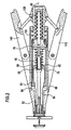
- FIGS. 1 to 4 an instrument according to the invention in the form of a surgical collet is shown.
- the collet 10 is used for applying a rivet-like fixing element 12, which comprises a first contact element 14 with a projecting from this, provided with retaining projections 16 elongate shaft 18 and a second contact element 20 which relative to the first contact element 14 on the shaft 18 in the direction of the first contact element 14 is displaceable towards.
- a displacement of the second contact element 20 relative to the first contact element 14 away from this is not possible due to the retaining projections 16 acting in this direction.
- two separate bone parts 22 and 24, which for example form parts of a human cranial bone, are fixed together by the two abutment elements 14 and 20 clamp the bone parts 22 and 24 on both sides between them.
- annular projection 26 is arranged, which has an annular constriction 28 has.
- the projection 26 is provided in this way virtually with a toothing comprising two teeth 30 and 32.
- the collet 10 comprises a first tool element in the form of a provided with a longitudinal bore 36 screw-34, which has an annular, pointing in the distal direction bearing surface 38 for application to the second contact element 20.
- the longitudinal bore 36 is dimensioned so that the shaft 18 can be passed with the projection 26 through the screw 34.
- the screw-in sleeve 34 is provided with an externally threaded portion 42, which corresponds to an internally threaded portion 44 at a distal end of a base body 40 of the collet 10. At its proximal end, the screw-in sleeve 34 has a conical surface 46, which points in the proximal direction. A tip of a cone defined by the conical surface 46 would lie on a longitudinal axis 48 of the collet 10, which simultaneously forms an axis of symmetry of the collet 10 and the fixation element 12.
- the main body 40 is in the form of an elongate sleeve and has an annular contact portion 50 adjacent to the conical surface 46 for two elongate clamping jaws 52 and 54 arranged symmetrically with respect to the longitudinal axis 48.
- the clamping jaws 52 and 54 are each provided with an oblique sliding surface 56 or 58 corresponding to the conical surface 46.
- Proximal matter free ends of the jaws 52 and 54 are mounted on bearing lugs 60 and 62 both pivotally and slidably, by a non-rotatably on the jaws 52 and 54 transverse to the longitudinal axis 48 oriented pin 68 or 70 a to the bearing lobes 60 and 62 respectively Slit 64 and 66 pointing obliquely from the longitudinal axis 48 in the proximal direction.
- the bearing lugs 60 and 62 are arranged distally radially projecting on a tension sleeve 72, which is connected on the proximal side with a rotationally symmetrical to the longitudinal axis 48 shaped bearing pin 74.
- the bearing pin 74 is on the distal side in a proximal end of a clamping sleeve 76 by means of a transversely to the longitudinal axis 48, both the bearing pin 74 and the clamping sleeve 76 passing through bolt 78 rotatably and axially displaceably secured.
- the clamping sleeve 76 is mounted axially displaceably in the base body 40 and secured against rotation relative to the base body 40 by a longitudinally extending away from a proximal end of the clamping sleeve 76 longitudinal groove 80 into which an inwardly of the clamping sleeve 76 in the direction of the longitudinal axis 48 back pointing protruding locking pin 82 dips.
- the clamping sleeve 76 has on the distal side a decreasing inner diameter, whereby a deflection surface 84 is formed, which points obliquely in the proximal direction to the longitudinal axis 48.
- the clamping jaws 52 and 54 have the deflection 84 correspondingly inclined sliding surfaces 86 and 88, which in an in FIG. 1 shown starting position substantially completely abut the deflection 84.
- a spiral spring 90 surrounding the tension sleeve 72 is supported on the one hand on the bearing lugs 60 and 62, on the other hand on the bearing pin 74.
- the coil spring 90 thus presses the clamping jaws 52 and 54 in the distal direction with their sliding surfaces 86 and 88 against the deflection surface 84 and the sliding surfaces 56 and 58 against the conical surface 46th
- the bearing pin 74 has a central bore 92, in which a cylindrical elongated tension bolt 94 is inserted and held by the bolt 78 rotationally fixed and axially immovable on the bearing pin 74.
- the distal end of the tension bolt 94 is slidably mounted in the tension sleeve 72, which has two parallel to the longitudinal axis 48 extending guide slots 96 and 98, in which a transversely to the longitudinal axis 48 of the tension bolt 94 penetrating guide pin 100 dips and in this way the tension sleeve 72 axially displaceable and secured against rotation secured to the draw bolt 94.
- the tension bolt 94 is connected to a total provided with the reference numeral 102 Switzerlandkraftbegrenzung 102.
- This comprises a bearing sleeve 104 which is longitudinally displaceably guided axially displaceably on a bearing ring 106 screwed into a proximal end of the base body 40.
- the bearing sleeve 104 carries in its interior an annular head 108 which is rotatably connected to a proximal end of the tension bolt 94.
- the tension bolt 94 is axially displaceably guided on a central axial sleeve bore 110.
- a stop ring 112 is screwed on the outside, which forms a stop face 114 pointing in the distal direction.
- a pin portion 120 reduced in diameter relative to the annular projection 118 dips into a corresponding cylindrical recess 122 of the bearing sleeve 104, which is open in the distal direction.
- a proximal end 126 of the journal 74 abuts a bottom 124 of the recess 122, which is penetrated by the sleeve bore 110.
- a disk spring block 128 is arranged in the bearing sleeve 104, which is supported on the one hand on the floor 124 and on the other hand on the head 108 and so the bearing pin 74 under prestress in the Recess 122 stops.
- a further spiral spring 130 Surrounding the bearing sleeve at its distal end is a further spiral spring 130 disposed within the base body 40, which is supported on the one hand on the stop ring 112 and on the other hand on the bearing ring 106. It thus presses the bearing sleeve 104 in the distal direction.
- Proximal note two bearing blocks 132 and 134 are arranged on the bearing sleeve 104 radially projecting symmetrical, on each of which a rod-shaped arm 136 and 138 is pivotally mounted.
- the links 136 and 138 are further pivotally connected to a respective pivoting handle 140 and 142, respectively.
- the pivoting handles 140 and 142 are held by means of two transverse to the longitudinal axis 48 oriented hinge pin 144 and 146 at radially projecting from the base body 40 bearing lugs 148 and 150 pivotally.
- the clamping jaws 52 and 54 are each provided with a toothing 152 or 154, which each have a plurality of pointing in the direction of the longitudinal axis 48 toward teeth 156 and 158.
- a toothing 152 or 154 which each have a plurality of pointing in the direction of the longitudinal axis 48 toward teeth 156 and 158.
- recordings 157 and 159 forming depressions are formed.
- the teeth 156 and 158 are all rounded.
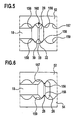
- a distance of the teeth 156 and 158 from each other is selected so that the projection 26 as a whole between two teeth 156 and 158 can be inserted. Such an engagement position is in FIG. 5 shown.
- the shape of a tip of the teeth 156 and 158 also corresponds substantially to the shape of the constriction 28 of the projection 26 on the shaft 18, so that in each case a tooth 156 and 158 of the clamping jaws 52 and 54 can dip into the constriction 28.
- Such an engagement position is in FIG. 6 shown.
- the teeth 152 and 154 are selected so that the teeth 30 and 32 of the projection 26 are half as far from each other as each two teeth 156 and 158. This corresponds to a division of the Gears 152 and 154 twice the pitch of a toothing 160 of the projection 26.
- engagement positions can be defined, which correspond to half the pitch of the pitch of the teeth 152 and 154. Two such, spaced apart at such a distance engagement positions are in the FIGS. 5 and 6 shown.
- the two contact elements 14 and 20 are applied to both sides of the two bone parts 22 and 24 to be joined to this and the shaft 18 passed through a bone gap 25.
- the shaft 18 with the projection 26 is inserted through the screw 34.
- the screw-in sleeve 34 is applied to the second contact element 20. This basic position is in FIG. 1 shown.
- the bearing sleeve 104 By pivoting the pivot handles 140 and 142 in the direction of the longitudinal axis 48, the bearing sleeve 104 is pulled in the proximal direction and compresses the coil spring 130 together. As long as the force exerted by the pivoting handles 140 and 142 is less than the force exerted by the disc spring block 128, the bearing pin 74 is held in the recess 122 of the bearing sleeve 104. Together with the bearing pin 74, the clamping sleeve 76 is pulled in the proximal direction, whereby the sliding surfaces 86 and 88 of the clamping jaws 52 and 54 slide on the deflection surface 84 of the clamping sleeve 76.
- the deflecting surface 84 thus acts as a deflecting element with which a tensile force acting in the direction of the longitudinal axis 48 is deflected into a thrust force in the direction of the longitudinal axis 48.
- the clamping jaws 52 and 54 are forcibly moved in the direction of the longitudinal axis 48, wherein a guide on the one hand by the voltage applied to the conical surface 46 sliding surfaces 56 and 58, on the other hand, by means of the guided in the slots 64 and 66 pins 68 and 70th
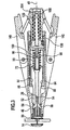
- FIG. 2 shows the engagement position of the jaws 52 and 54 on the projection 26 in a distal position thereof.
- FIG. 5 corresponds to an enlarged section of the FIG. 2 ,
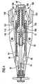
- FIG. 3 a position of the collet 10 is shown, in which the projection 26 has been relatively moved away from the second contact element 20, so that the second contact element 20 already occupies a direction towards the first contact element 14 changed position.
- the tensile force limitation 102 begins to act.
- the tensile force exerted on the bearing sleeve 104 now exceeds the force exerted by the disk spring block 128, as a result of which the disk spring block 128 is compressed.
- An axial position of the clamping sleeve 76 relative to the base body 40 thereby remains practically constant.
- the coil spring 130 as well as the disc spring block 128 is further compressed. This position is in FIG. 4 shown.
- the pivot handles 140 and 142 are pivoted away from the longitudinal axis 48 again. This can be done automatically, for example by means of a leaf spring, not shown.
- the coil springs 90 and 130 allows the arrangement of the collet 10 that in the in FIG. 3 shown pull position when pivoting back the pivot handles 140 and 142 away from the longitudinal axis 48, first the jaws 52 and 54 are moved radially away from the longitudinal axis 48 and the projection 26 away, when the train is reduced to the bearing sleeve 104.
- the jaws 52 and 54 release the projection 26 on the shaft 18. Another pivoting of the pivot handles 140 and 142 back into the in FIG.
Abstract
Description
Die Erfindung betrifft ein chirurgisches Instrument zum Anlegen einer Knochenplatten-Fixiervorrichtung, welche ein erstes Knochenanlageelement mit einem von diesem abstehenden stabförmigen, eine Längsrichtung definierenden Verbindungsglied und ein auf dem Verbindungsglied in Richtung auf das erste Knochenanlageelement verschiebbares zweites Knochenanlageelement aufweist, mit einem an dem zweiten Knochenanlageelement in einer Anlagestellung anlegbaren ersten Werkzeugelement und einem von dem ersten Werkzeugelement entfernbaren zweiten Werkzeugelement, mit einer Transportvorrichtung zum schrittweisen Transportieren des Verbindungsglieds mit dem zweiten Werkzeugelement in mehreren Transportschritten in einer proximalen Richtung weg von dem in der Anlagestellung am zweiten Knochenanlageelement anliegenden ersten Werkzeugelement, wobei das zweite Werkzeugelement mehrere Aufnahmen für einen am Verbindungsglied abstehenden Vorsprung aufweist, wobei das zweite Werkzeugelement eine eine Mehrzahl von Zähnen umfassende Verzahnung aufweist und die Verzahnung die Aufnahmen umfasst, wobei der Vorsprung eine mindestens zwei Zähne umfassende Vorsprungverzahnung aufweist, bei jedem Transportschritt mindestens teilweise mit einer Aufnahme in einer Eingriffsposition in Eingriff bringbar und in dieser in Längsrichtung unbeweglich am zweiten Werkzeugelement gehalten ist und wobei von einem Transportschritt zu einem nachfolgenden Transportschritt der Vorsprung mit einer in proximalerer Richtung am zweiten Werkzeugelement angeordneten Aufnahme in Eingriff bringbar ist.The invention relates to a surgical instrument for applying a bone plate fixing device, which has a first bone contact element with a projecting therefrom rod-shaped, a longitudinally defining link and a displaceable on the connecting member in the direction of the first bone abutment second bone abutment member, with one on the second bone abutment element in a contact position applicable first tool element and a removable from the first tool element second tool element, with a transport device for gradually transporting the connecting member with the second tool element in a plurality of transport steps in a proximal direction away from the applied in the contact position on the second bone abutment element first tool element, said second tool element has a plurality of receptacles for a projection projecting on the connecting member, wherein the second tool element is a one more number of teeth comprising teeth and the toothing comprises the receptacles, wherein the projection has at least two teeth projection teeth, at each transport step at least partially engageable with a receptacle in an engaged position and held in this longitudinally immovable on the second tool element and wherein, from a transport step to a subsequent transport step, the projection can be brought into engagement with a receptacle arranged in the more proximal direction on the second tool element.
Ferner betrifft die vorliegende Erfindung eine Knochenplatten-Fixiervorrichtung, welche ein erstes Knochenanlageelement mit einem von diesem abstehenden stabförmigen, eine Längsrichtung definierenden Verbindungsglied und ein auf dem Verbindungsglied in Richtung auf das erste Knochenanlageelement verschiebbares zweites Knochenanlageelement aufweist, wobei das Verbindungsglied mit Rückhaltevorsprüngen versehen ist, wodurch eine Verschiebung des zweiten Anlageelements relativ zum ersten Anlageelement von diesem weg aufgrund der in diese Richtung wirkenden Rückhaltevorsprünge unmöglich ist, wobei das Verbindungsglied einen abstehenden Vorsprung aufweist, welcher eine mindestens zwei Zähne umfassende Vorsprungverzahnung aufweist und wobei die Knochenplatten-Fixiervorrichtung mit einem chirurgischen Instrument anlegbar ist, welches Instrument ein an dem zweiten Knochenanlageelement in einer Anlagestellung anlegbares erstes Werkzeugelement und ein von dem ersten Werkzeugelement entfernbares zweites Werkzeugelement, eine Transportvorrichtung zum schrittweisen Transportieren des Verbindungsglieds mit dem zweiten Werkzeugelement in mehreren Transportschritten in einer proximalen Richtung weg von dem in der Anlagestellung am zweiten Knochenanlageelement anliegenden ersten Werkzeugelement umfasst, wobei das zweite Werkzeugelement mehrere Aufnahmen für den Vorsprung aufweist, wobei das zweite Werkzeugelement eine eine Mehrzahl von Zähnen umfassende Verzahnung aufweist und die Verzahnung die Aufnahmen umfasst.Furthermore, the present invention relates to a bone plate fixing device, which has a first bone contact element with a projecting therefrom rod-shaped, longitudinally defining link and a displaceable on the connecting member in the direction of the first bone abutment second bone abutment member, wherein the connecting member is provided with retaining projections, whereby a displacement of the second abutment element relative to the first abutment element away from the latter is impossible because of the retaining projections acting in this direction, wherein the connecting member has a protruding projection which has at least two teeth projection teeth and wherein the bone plate fixing device can be applied with a surgical instrument which instrument entred on the second bone engaging element in a contact position first tool element and one of the first tool element entfer nbares second tool element, a transport device for the stepwise transport of the connecting member with the second tool element in a plurality of transport steps in a proximal direction away from the applied in the contact position on the second bone abutment element first tool element, wherein the second tool element has a plurality of receptacles for the projection, wherein the second Tool element has a toothing comprising a plurality of teeth and the toothing comprises the recordings.
Ein Instrument zum Anlegen einer Knochenplatten-Fixiervorrichtung ist beispielsweise aus der
Ferner sind Instrumente sowie Knochenplatten-Fixiervorrichtung der eingangs beschriebenen Art aus der
Mit dem bekannten Instrument ist jedoch ein definierter Transport des Verbindungsglieds relativ zum zweiten Knochenanlageelement nicht eindeutig gewährleistet. Ferner ist es schwierig, ein glattes Verbindungsglied sicher zu greifen. Bei strukturierten Verbindungsgliedern ergibt sich das Problem, dass sich eine Struktur des Verbindungsglieds in die Spannbacken eingraben und zu einer Beschädigung derselben führen kann. In jedem Fall besteht die Gefahr, bei hohen auf das zweite Werkzeugelement wirkenden Zugkräften, dass die Spannbacken am Verbindungsglied abrutschen können. Ferner läßt sich das Instrument nur schwer reinigen, wenn die Spannbacken Beschädigungen aufgrund scharfkantiger Strukturen der Verbindungsglieder aufweisen.With the known instrument, however, a defined transport of the connecting member relative to the second bone contact element is not clearly guaranteed. Furthermore, it is difficult to securely grip a smooth link. In structured links, there is the problem that a structure of the link buried in the jaws and can lead to damage of the same. In any case, there is a risk at high acting on the second tool element tensile forces that the clamping jaws can slip on the connecting member. Furthermore, the instrument is difficult to clean, if the jaws have damage due to sharp-edged structures of the links.
Es ist daher Aufgabe der vorliegenden Erfindung, ein chirurgisches Instrument der eingangs beschriebenen Art so zu verbessern, dass die Reinigbarkeit des Instruments verbessert wird.It is therefore an object of the present invention to improve a surgical instrument of the type described above so that the cleanability of the instrument is improved.
Diese Aufgabe wird bei einem chirurgischen Instrument der eingangs beschriebenen Art erfindungsgemäß dadurch gelöst, dass die Verzahnung des zweiten Werkzeugelements eine Teilung aufweist, welche einem ganzzahligenechten Vielfachen einer Teilung der Vorsprungverzahnung entspricht.This object is achieved in a surgical instrument of the type described above according to the invention that the toothing of the second tool element has a pitch which corresponds to a integer integer multiples of a pitch of the projection teeth.
Das erfindungsgemäße Instrument ermöglicht es, den Vorsprung des Verbindungsglieds definiert und mit einer vorgegebenen Schrittweite durch das Instrument hindurchzureichen. Die Ausbildung von Aufnahmen zum Aufnehmen des Vorsprungs ermöglicht es, die Aufnahmen entsprechend groß auszubilden, so dass das zweite Werkzeugelement und damit das gesamte Instrument gut gereinigt werden können. In der Eingriffsposition ist eine Bewegung des Verbindungsglieds relativ zum zweiten Werkzeugelement in Längsrichtung nicht möglich. Dadurch kann das zweite Werkzeugelement nicht vom mittels des Vorsprungs in einer Aufnahme gehaltenen Verbindungsglied abrutschen. Damit ergibt sich eine besonders einfache Ausgestaltung des zweiten Werkzeugelements, weist das zweite Werkzeugelement eine eine Mehrzahl von Zähnen umfassende Verzahnung auf und umfasst die Verzahnung die Aufnahmen. Denkbar wäre es, den Vorsprung in Form eines Kopfes auszubilden. Um jedoch eine Verbindung zwischen dem zweiten Werkzeugelement und dem Vorsprung zu verbessern, weist der Vorsprung eine mindestens zwei Zähne umfassende Vorsprungverzahnung auf. Dadurch ist es möglich, dass wahlweise ein Zahn der Verzahnung des zweiten Werkzeugelements zwischen die mindestens zwei Zähne der Vorsprungverzahnung eingreift. Denkbar ist es auch, dass der Vorsprung als Ganzes, also auch seine mindestens zwei Zähne umfassende Vorsprungverzahnung, in eine einzelne Aufnahme der Verzahnung des zweiten Werkzeugelements einführbar ist. Das Reinigen des zweiten Werkzeugelements wirt erleichtert, dadurch, dass die Verzahnung des zweiten Werkzeugelements erfindungsgemäß eine Teilung aufweist, welche einem ganzzahligenechten Vielfachen einer Teilung der Vorsprungverzahnung entspricht. Dadurch ergeben sich besonders große Abstände der Zähne der Verzahnung des zweiten Werkzeugelements. Insbesondere kann ein Teilungsverhältnis 2:1 oder 3:1 betragen.The instrument according to the invention makes it possible to define the projection of the connecting member and to pass it through the instrument at a predetermined pitch. The formation of recordings for receiving the projection makes it possible to make the recordings correspondingly large, so that the second tool element and thus the entire instrument can be cleaned well. In the engaged position movement of the connecting member relative to the second tool element in the longitudinal direction is not possible. As a result, the second tool element can not slip off the connecting member held by the projection in a receptacle. This results in a particularly simple embodiment of the second tool element, the second tool element has a toothing comprising a plurality of teeth and the toothing comprises the receptacles. It would be conceivable to form the projection in the form of a head. However, in order to improve a connection between the second tool element and the projection, the projection has a projection toothing comprising at least two teeth. This makes it possible that optionally a tooth of the toothing of the second tool element engages between the at least two teeth of the projection toothing. It is also conceivable that the projection as a whole, including its at least two teeth comprehensive projection teeth, in a single recording of the toothing of the second tool element is inserted. The cleaning of the second tool element is facilitated by the fact that the toothing of the second tool element according to the invention has a pitch which corresponds to an integer multiple of a pitch of the projection toothing. This results in particularly large distances between the teeth of the toothing of the second tool element. In particular, a division ratio can be 2: 1 or 3: 1.
Günstig ist es, wenn das zweite Werkzeugelement in einer relativ zum ersten Werkzeugelement distalen Stellung mit dem Vorsprung in der Eingriffsposition in Eingriff bringbar ist, wenn das zweite Werkzeugelement in der Eingriffsposition in proximaler Richtung von der distalen Stellung in eine vom ersten Werkzeugelement entferntere proximale Stellung bringbar ist und wenn das zweite Werkzeugelement in der proximalen Stellung von der Eingriffsposition in eine Löseposition bringbar ist, in welcher das zweite Werkzeugelement und der Vorsprung außer Eingriff sind. Ein derart aufgebautes Instrument ermöglicht es, den Vorsprung mit dem zweiten Werkzeugelement zu fassen und in proximaler Richtung zu bewegen, so dass das am ersten Werkzeugelement anliegende zweite Knochenanlageelement relativ zum Vorsprung des Verbindungsglieds bewegt wird. Zum Nachfassen, also einem nochmaligen Greifen des Vorsprungs mit dem zweiten Werkzeugelement, läßt sich die Eingriffsposition lösen, das heißt, das zweite Werkzeugelement und der Vorsprung sind wieder relativ zueinander in Längsrichtung verschiebbar. Dies ist nur in der Löseposition möglich.It is expedient if the second tool element can be brought into engagement with the projection in the engagement position in a position which is distal relative to the first tool element, if the second tool element can be brought in the engagement position in the proximal direction from the distal position into a proximal position remote from the first tool element is and if the second Tool element in the proximal position of the engagement position can be brought into a release position in which the second tool element and the projection are disengaged. An instrument constructed in this way makes it possible to grasp the projection with the second tool element and to move it in the proximal direction, so that the second bone abutment element resting against the first tool element is moved relative to the projection of the connecting member. To follow up, so a repeated gripping the projection with the second tool element, the engagement position can be solved, that is, the second tool element and the projection are again relative to each other in the longitudinal direction displaceable. This is only possible in the release position.
Vorteilhaft ist es, wenn das zweite Werkzeugelement in der Löseposition von der proximalen Stellung in die distale Stellung bringbar ist. Der Vorsprung behält dann seine relative Position zum zweiten Knochenanlageelement bei, während das zweite Werkzeugelement am Vorsprung vorbei in die distale Stellung gebracht werden kann. Auf diese Weise läßt sich ein schrittweiser Transport des Vorsprungs mit dem Instrument in proximaler Richtung realisieren.It is advantageous if the second tool element can be brought from the proximal position to the distal position in the release position. The projection then retains its relative position to the second bone engaging element, while the second tool element can be brought past the projection to the distal position. In this way, a stepwise transport of the projection with the instrument in the proximal direction can be realized.
Damit der Vorsprung sicher am zweiten Werkzeugelement in Längsrichtung unbeweglich haltbar ist, ist es vorteilhaft, wenn das zweite Werkzeugelement quer zur Längsrichtung relativ zum Vorsprung bewegbar ist. Es ermöglicht auf diese Weise quasi eine Verriegelung des Vorsprungs am zweiten Werkzeugelement.In order for the projection to be securely held immovably on the second tool element in the longitudinal direction, it is advantageous if the second tool element is movable transversely to the longitudinal direction relative to the projection. It allows in this way, as it were, a locking of the projection on the second tool element.
Besonders einfach wird der Aufbau des Instruments, wenn das zweite Werkzeugelement einen ersten und einen zweiten Spannbacken umfasst und wenn mindestens einer der beiden Spannbacken die Aufnahmen trägt. Der Vorsprung kann auf diese Weise zwischen den beiden Spannbacken gehalten werden. Selbstverständlich ist es auch möglich, beide Spannbacken mit Aufnahmen zu versehen, so dass der Vorsprung beidseitig durch Aufnahmen der Spannbacken gehalten werden kann.The structure of the instrument becomes particularly simple if the second tool element comprises a first and a second clamping jaw and if at least one of the two clamping jaws carries the receptacles. The projection can be held in this way between the two jaws. Of course, it is also possible to provide both clamping jaws with receptacles, so that the projection can be held on both sides by recordings of the clamping jaws.
Um einen Transport des Vorsprungs vom zweiten Knochenanlageelement weg in definierter Weise durchzuführen, kann es vorteilhaft sein, wenn das Instrument derart ausgebildet ist, dass von einem Transportschritt zu einem nachfolgenden Transportschritt der Vorsprung mindestens um einen Transportweg in proximaler Richtung transportierbar ist und wenn der Transportweg dem kleineren der Zahnabstände der Verzahnung und der Vorsprungverzahnung entspricht. Dies ermöglicht es, einen definierten kleinsten Transportweg durch die Form der Verzahnung beziehungsweise der Vorsprungverzahnung vorzugeben. Selbstverständlich kann ein tatsächlicher Transportweg oder -hub einem ganzzähligen Vielfachen des kleinsten Transportwegs entsprechen.In order to carry out a transport of the projection away from the second bone abutment element in a defined manner, it may be advantageous if the instrument is designed such that from a transport step to a subsequent transport step the projection is transportable at least one transport path in the proximal direction and if the transport path smaller corresponds to the tooth spacing of the toothing and the projection teeth. This makes it possible to specify a defined smallest transport path through the shape of the toothing or the projection toothing. Of course, an actual transport path or stroke may correspond to an integer multiple of the smallest transport path.
Um eine Relativbewegung in Längsrichtung in der Eingriffsposition zwischen dem Vorsprung und dem zweiten Werkzeugelement zu vermeiden, kann es vorteilhaft sein, wenn der mindestens eine Zahn der Verzahnung quer zur Längsrichtung in die Halteaufnahme einführbar ist.In order to avoid a relative movement in the longitudinal direction in the engagement position between the projection and the second tool element, it may be advantageous if the at least one tooth of the toothing is insertable transversely to the longitudinal direction in the holding receptacle.
Um eine Beschädigung des zweiten Werkzeugelements und auch des Verbindungsglieds zu vermeiden, ist es vorteilhaft, wenn die Aufnahmen kantenfrei ausgebildet sind. Die kantenfreie Ausgestaltung hat darüber hinaus den Vorteil, dass der Vorsprung beim Eintauchen in eine Aufnahme durch vorteilhafte Rundungen der Aufnahmen in die Aufnahmen hinein geführt wird.In order to avoid damage to the second tool element and also the connecting member, it is advantageous if the recordings are formed edge-free. The edge-free embodiment also has the advantage that the projection is guided into the receptacles when immersed in a recording by advantageous curves of the recordings.
Für eine einfache Handhabung des Instruments ist es günstig, wenn das Instrument einen Grundkörper und mindestens ein am Grundkörper beweglich gelagertes Betätigungselement aufweist und wenn durch eine Bewegung des Betätigungselements relativ zum Grundkörper eine Zugkraft auf das zweite Werkzeugelement in Längsrichtung von dem ersten Werkzeugelement weg übertragbar ist. Dadurch läßt sich das Werkzeugelement auf einfache Weise in Längsrichtung bewegen.For ease of handling of the instrument, it is advantageous if the instrument has a base body and at least one actuating element movably mounted on the base body and if, by a movement of the Actuating element relative to the base body, a tensile force on the second tool element in the longitudinal direction of the first tool element is transferable away. As a result, the tool element can be moved in a simple manner in the longitudinal direction.
Gemäß einer bevorzugten Ausführungsform der Erfindung kann vorgesehen sein, dass durch eine Bewegung des Betätigungselements relativ zum Grundkörper eine Haltekraft auf das zweite Werkzeugelement quer zur Längsrichtung übertragbar ist. Dies gestattet es, durch die Bewegung des Betätigungselements gleichzeitig eine Haltekraft und eine Zugkraft auf das zweite Werkzeugelement auszuüben. Eine Bedienperson muß somit nur das Betätigungselement bewegen und kann dadurch den Vorsprung vom ersten Werkzeugelement weg bewegen.According to a preferred embodiment of the invention can be provided that by a movement of the actuating element relative to the base body, a holding force on the second tool element transversely to the longitudinal direction is transferable. This makes it possible to simultaneously exert a holding force and a tensile force on the second tool element by the movement of the actuating element. An operator thus only has to move the actuating element and can thereby move the projection away from the first tool element.
Vorteilhaft ist es, wenn ein Kraftumlenkglied zum Umlenken einer in Längsrichtung wirkenden Zugkraft in die quer zur Längsrichtung wirkende Haltekraft vorgesehen ist. Durch Ausüben einer Zugkraft wird nicht nur das zweite Werkzeugelement in Richtung der Zugkraft bewegt, sondern gleichzeitig kann mit dem zweiten Werkzeugelement eine Haltekraft auf das Verbindungsglied, insbesondere auf den Vorsprung, ausgeübt werden.It is advantageous if a force deflecting element is provided for deflecting a tensile force acting in the longitudinal direction into the holding force acting transversely to the longitudinal direction. By applying a tensile force not only the second tool element is moved in the direction of the tensile force, but at the same time can be exercised with the second tool element, a holding force on the connecting member, in particular on the projection.
Ein besonders kompakter Aufbau des Instruments ergibt sich, wenn der mindestens eine Spannbacken an dem Kraftumlenkglied anliegt und an diesem während einer Bewegung des Kraftumlenkglieds in Längsrichtung führbar ist. Dies ist beispielsweise durch schräge Aufgleitflächen am Kraftumlenkglied zu realisieren. Ferner kann eine Kraft direkt vom Kraftumlenkglied auf den mindestens einen Spannbacken übertragen werden, weitere Teile werden hierfür nicht benötigt.A particularly compact design of the instrument results when the at least one clamping jaw bears against the force deflecting member and can be guided on it during a movement of the force deflecting member in the longitudinal direction. This can be realized for example by oblique sliding surfaces on the force deflecting member. Furthermore, a force can be transmitted directly from the force deflecting member to the at least one clamping jaw, further parts are not required for this purpose.
Damit von dem Kraftumlenkglied Zugkräfte übertragen werden können, ist es vorteilhaft, wenn auf das Kraftumlenkglied von dem mindestens einen Betätigungsglied eine Zugkraft übertragbar ist.So that tensile forces can be transmitted by the force deflecting member, it is advantageous if a tensile force can be transmitted to the force deflecting member of the at least one actuating member.
Um einen Rückstoß oder ein Rückschlagen des zweiten Werkzeugelements am Instrument zu vermeiden, kann vorgesehen sein, dass sich der mindestens eine Spannbacken in Längsrichtung federnd am Kraftumlenkglied abstützt. Dadurch wird er stets unter Vorspannung am Kraftumlenkglied gehalten, wodurch eine besonders schonende Anwendung des Instruments möglich wird.In order to avoid a recoil or a kickback of the second tool element on the instrument, it can be provided that the at least one clamping jaw is resiliently supported on the force deflecting member in the longitudinal direction. As a result, it is always held under pretension on Kraftumlenkglied, whereby a particularly gentle application of the instrument is possible.
Um zusätzlich Rückstoßkräfte aufzunehmen, falls das mindestens eine Betätigungselement schlagartig gelöst wird, kann sich das Kraftumlenkglied federnd am Grundkörper abstützen.In order to additionally absorb recoil forces, if the at least one actuating element is released abruptly, the force deflecting member can be resiliently supported on the base body.
Eine Beschädigung des Instruments kann wirkungsvoll vermieden werden, wenn eine Zugkraftbegrenzungsvorrichtung zum Begrenzen der Zugkraft in Längsrichtung vorgesehen ist. Unabhängig davon, wie groß eine von einer Bedienperson ausgeübte Kraft auf das Betätigungselement ist, wird eine maximale Zugkraft mittels der Zugkraftbegrenzungsvorrichtung begrenzt.Damage to the instrument can be effectively avoided if a tensile force limiting device for limiting the tensile force in the longitudinal direction is provided. Regardless of how great a force exerted by an operator on the actuating element, a maximum tensile force is limited by the Zugkraftbegrenzungsvorrichtung.
Um Kräfte vom Betätigungselement begrenzt auf das Kraftumlenkglied zu übertragen, ist es günstig, wenn mit der Zugkraftbegrenzungsvorrichtung eine von dem mindestens einen Betätigungselement eingeleitete Kraft begrenzt auf das Kraftumlenkglied übertragbar ist.In order to transmit forces from the actuating element limited to the force deflecting member, it is advantageous if, with the tensile force limiting device, a force introduced by the at least one actuating element is limitedly transferable to the force deflecting member.
Besonders gute Dämpfungseigenschaften lassen sich für das Instrument erreichen, wenn sich das Kraftumlenkglied federnd an der Zugkraftbegrenzungsvorrichtung abstützt.Particularly good damping properties can be achieved for the instrument when the force deflection member is resiliently supported on the traction limiting device.
Um die Dämpfungseigenschaften des Instruments weiter zu verbessern, kann sich die Zugkraftbegrenzungsvorrichtung federnd am Grundkörper abstützen. Durch die federnde Abstützung werden Rückstoßkräfte abgemildert, die bei einem schlagartigen Loslassen des mindestens einen Betätigungselements auftreten können.In order to further improve the damping properties of the instrument, the tensile force limiting device can be resiliently supported on the base body. By the resilient support recoil forces are mitigated, which can occur in a sudden release of the at least one actuating element.
Um eine Trennung einer Hub- und Zugbewegung des zweiten Werkzeugelements zu erreichen, ist es vorteilhaft, wenn der mindestens eine Spannbacken an einem in Längsrichtung am Grundkörper verschieblich gelagerten Schub- und Zugelement gelagert ist und wenn von dem mindestens einen Betätigungselement eine Zugkraft auf das Schub- und Zugelement übertragbar ist.In order to achieve a separation of a lifting and pulling movement of the second tool element, it is advantageous if the at least one clamping jaw is mounted on a longitudinally displaceably mounted on the base body push and pull element and if of the at least one actuating element, a tensile force on the thrust and tension element is transferable.
Die eingangs gestellte Aufgabe wird bei einer Knochenplatten-Fixiervorrichtung der eingangs beschriebenen Art erfindungsgemäß dadurch gelöst, dass die Verzahnung des zweiten Werkzeugelements eine Teilung aufweist, welche einem ganzzahligenechten Vielfachen einer Teilung der Vorsprungverzahnung entspricht.The object stated in the introduction is achieved in a bone plate fixing device of the type described above according to the invention in that the toothing of the second tool element has a pitch which corresponds to a number-integer multiple of a pitch of the projection toothing.
Eine besonders sichere Verbindung in der Eingriffsposition ergibt sich, wenn der Vorsprung formschlüssig in die Aufnahmen einführbar ist. Wenn der Vorsprung korrespondierend zu einer Aufnahme ausgebildet ist, kann es auch nicht zu Beschädigungen des zweiten Werkzeugelements kommen. Außerdem läßt sich das zweite Werkzeugelement auf einfache Weise reinigen, wenn der Vorsprung und die Aufnahme entsprechend groß genug ausgebildet sind.A particularly secure connection in the engaged position results when the projection is positively inserted into the receptacles. If the projection is formed corresponding to a receptacle, it can also not lead to damage of the second tool element. In addition, the second tool element can be cleaned in a simple manner, if the projection and the receptacle are designed to be large enough.
Vorteilhaft ist es, wenn der Vorsprung eine Halteaufnahme zum Aufnehmen mindestens eines Zahns der Verzahnung aufweist. Dies hat den Vorteil, dass einerseits der Vorsprung als Ganzes in eine Aufnahme des zweiten Werkzeugelements einführbar ist und dass andererseits ein Zahn der Verzahnung in die Halteaufnahme einführbar ist. Damit läßt sich eine doppelte Verbindung realisieren, beispielsweise in Form von zwei formschlüssig ineinandergreifenden Zähnen beziehungsweise Lücken zwischen zwei Zähnen.It is advantageous if the projection has a holding receptacle for receiving at least one tooth of the toothing. This has the advantage that, on the one hand, the projection as a whole can be introduced into a receptacle of the second tool element and, on the other hand, that a tooth of the toothing can be inserted into the Holding receptacle is insertable. Thus, a double connection can be realized, for example in the form of two positively intermeshing teeth or gaps between two teeth.
Besonders einfach wird der Aufbau der Vorrichtung, wenn die Vorsprungverzahnung die Halteaufnahme umfasst.The construction of the device becomes particularly simple if the projection toothing comprises the holding receptacle.
Günstig ist es, wenn die Halteaufnahme eine Ringnut umfasst. Eine solche läßt sich an dem Vorsprung oder direkt an dem Verbindungsglied besonders einfach herstellen.It is advantageous if the holding receptacle comprises an annular groove. Such can be particularly easy to produce on the projection or directly on the connecting member.
Damit durch den Vorsprung keine Beschädigungen am zweiten Werkzeugelement hervorgerufen werden können, ist es von Vorteil, wenn der Vorsprung kantenfrei ausgebildet ist. Auf diese Weise kann er noch besser in eine Aufnahme des zweiten Werkzeugelements hineingleiten. Hilfreich sind dabei abgerundete Formen des Vorsprungs.So that no damage to the second tool element can be caused by the projection, it is advantageous if the projection is formed edge-free. In this way, he can slide even better into a receptacle of the second tool element. Helpful are rounded forms of the projection.
Weitere vorteilhafte Weiterbildungen sind in den Unteransprüchen angegeben.Further advantageous developments are specified in the subclaims.
Die nachfolgende Beschreibung einer bevorzugten Ausführungsform der Erfindung dient im Zusammenhang mit der Zeichnung der näheren Erläuterung. Es zeigen:
- Figur 1:
- eine erfindungsgemäße Spannzange mit Spannbacken in einer dis- talen Lösestellung;
- Figur 2:
- das Instrument aus
Figur 1 mit den Spannbacken in einer distalen Eingriffsposition; - Figur 3:
- das Instrument aus
Figur 1 mit den Spannbacken in einer proxima- len Zugstellung; - Figur 4:
- das Instrument aus
Figur 3 bei wirkender Zugkraftbegrenzung; - Figur 5:
- eine mögliche erste Eingriffsposition eines Vorsprungs eines Verbin- dungsglieds an Zähnen der Spannbacken; und
- Figur 6:
- eine zweite mögliche Eingriffsposition des Vorsprungs an den Zäh- nen der Spannbacken.
- FIG. 1:
- a collet according to the invention with clamping jaws in a disalt release position;
- FIG. 2:
- the instrument off
FIG. 1 with the jaws in a distal engagement position; - FIG. 3:
- the instrument off
FIG. 1 with the clamping jaws in a proximal pull position; - FIG. 4:
- the instrument off
FIG. 3 with acting tensile force limitation; - FIG. 5:
- a possible first engagement position of a projection of a connecting member on teeth of the clamping jaws; and
- FIG. 6:
- a second possible engagement position of the projection on the teeth of the clamping jaws.
In den
An einem vom ersten Anlageelement 14 weg weisenden Ende des Schafts 18 ist ein ringförmiger Vorsprung 26 angeordnet, welcher eine ringförmige Einschnürung 28 aufweist. Der Vorsprung 26 ist auf diese Weise quasi mit einer Verzahnung umfassend zwei Zähne 30 und 32 versehen.At an end of the
Mittels der Spannzange 10 ist eine Relativbewegung zwischen den beiden Anlageelementen 14 und 20 realisierbar. Hierfür umfasst die Spannzange 10 ein erstes Werkzeugelement in Form einer mit einer Längsbohrung 36 versehenen Einschraubhülse 34, die eine ringförmige, in distaler Richtung weisende Anlagefläche 38 zum Anlegen am zweiten Anlageelement 20 aufweist. Die Längsbohrung 36 ist so bemessen, dass der Schaft 18 mit dem Vorsprung 26 durch die Einschraubhülse 34 hindurchgeführt werden kann.By means of the
Die Einschraubhülse 34 ist mit einem Außengewindeabschnitt 42 versehen, welcher zu einem Innengewindeabschnitt 44 an einem distalen Ende eines Grundkörpers 40 der Spannzange 10 korrespondiert. An ihrem proximalen Ende weist die Einschraubhülse 34 eine Kegelmantelfläche 46 auf, die in proximaler Richtung weist. Eine Spitze eines von der Kegelmantelfläche 46 definierten Kegels würde auf einer Längsachse 48 der Spannzange 10 liegen, welche gleichzeitig eine Symmetrieachse der Spannzange 10 und des Fixierungselementes 12 bildet.The screw-in
Der Grundkörper 40 ist in Form einer langgestreckten Hülse ausgebildet und weist an die Kegelmantelfläche 46 angrenzend einen ringförmigen Anlageabschnitt 50 für zwei symmetrisch zur Längsachse 48 angeordnete langgestreckte Spannbacken 52 und 54 auf. Distalseitig sind die Spannbacken 52 und 54 jeweils mit einer zur Kegelmantelfläche 46 korrespondierenden schrägen Aufgleitfläche 56 beziehungsweise 58 versehen. Proximalseitig sind freie Enden der Spannbacken 52 und 54 an Lagerlappen 60 und 62 sowohl schwenkbar als auch verschiebbar gelagert, und zwar indem ein drehfest an den Spannbacken 52 beziehungsweise 54 quer zur Längsachse 48 orientierter Stift 68 beziehungsweise 70 einen an den Lagerlappen 60 beziehungsweise 62 schräg von der Längsachse 48 in proximaler Richtung weisenden Schlitz 64 beziehungsweise 66 durchsetzt. Die Lagerlappen 60 und 62 sind distalseitig radial abstehend an einer Zughülse 72 angeordnet, welche proximalseitig mit einem rotationssymmetrisch zur Längsachse 48 geformten Lagerzapfen 74 verbunden ist. Der Lagerzapfen 74 ist distalseitig in ein proximales Ende einer Klemmhülse 76 mittels eines quer zur Längsachse 48 sowohl den Lagerzapfen 74 als auch die Klemmhülse 76 durchsetzenden Bolzens 78 drehfest und auch axial verschieblich gesichert.The
Die Klemmhülse 76 ist im Grundkörper 40 axial verschieblich gelagert und gegen ein Verdrehen relativ zum Grundkörper 40 gesichert durch eine sich außen von einem proximalen Ende der Klemmhülse 76 weg erstreckenden Längsnut 80, in welche ein innen von der Klemmhülse 76 in Richtung auf die Längsachse 48 hin weisend abstehender Sicherungszapfen 82 eintaucht. Die Klemmhülse 76 weist distalseitig einen sich verringernden Innendurchmesser auf, wodurch eine Umlenkfläche 84 gebildet wird, die schräg in proximaler Richtung auf die Längsachse 48 hin weist. Die Spannbacken 52 und 54 weisen zur Umlenkfläche 84 korrespondierend geneigte Gleitflächen 86 beziehungsweise 88 auf, die in einer in
Eine die Zughülse 72 umgebende Spiralfeder 90 stützt sich einerseits an den Lagerlappen 60 und 62, andererseits am Lagerzapfen 74 ab. Die Spiralfeder 90 drückt somit die Spannbacken 52 und 54 in distaler Richtung mit ihren Gleitflächen 86 und 88 gegen die Umlenkfläche 84 sowie die Aufgleitflächen 56 und 58 gegen die Kegelmantelfläche 46.A
Der Lagerzapfen 74 weist eine zentrale Bohrung 92 auf, in welcher ein zylindrischer langgestreckter Zugbolzen 94 eingesetzt und mittels des Bolzens 78 drehfest und axial unverschieblich am Lagerzapfen 74 gehalten ist. Distalseitig ist der Zugbolzen 94 in der Zughülse 72 verschiebbar gelagert, welche zwei sich parallel zur Längsachse 48 erstreckende Führungsschlitze 96 und 98 aufweist, in welche ein quer zur Längsachse 48 den Zugbolzen 94 durchsetzender Führungsstift 100 eintaucht und auf diese Weise die Zughülse 72 axial verschieblich und gegen eine Verdrehung gesichert am Zugbolzen 94 hält.The bearing
Proximalseitig ist der Zugbolzen 94 mit einer insgesamt mit dem Bezugszeichen 102 versehenen Zugkraftbegrenzung 102 verbunden. Diese umfasst eine Lagerhülse 104, welche längsverschieblich an einem in ein proximales Ende des Grundkörpers 40 eingeschraubten Lagerring 106 axial verschieblich geführt ist. Die Lagerhülse 104 führt in ihrem Inneren einen ringförmigen Kopf 108, welcher drehfest mit einem proximalen Ende des Zugbolzens 94 verbunden ist. Distalseitig wird der Zugbolzen 94 an einer zentralen axialen Hülsenbohrung 110 axial verschieblich geführt.Proximalseitig the
Auf ein distales Ende der Lagerhülse 104 ist außen ein Anschlagring 112 aufgeschraubt, welcher eine in distaler Richtung weisende Anschlagfläche 114 bildet. An der Anschlagfläche 114 liegt in der in
Den Zugbolzen 94 umgebend ist in der Lagerhülse 104 ein Tellerfederblock 128 angeordnet, der sich einerseits am Boden 124 und andererseits am Kopf 108 abstützt und so den Lagerzapfen 74 unter Vorspannung in der Ausnehmung 122 hält. Die Lagerhülse an ihrem distalseitigen Ende umgebend ist eine weitere Spiralfeder 130 innerhalb des Grundkörpers 40 angeordnet, die sich einerseits am Anschlagring 112 und andererseits am Lagerring 106 abstützt. Sie drückt damit insgesamt die Lagerhülse 104 in distaler Richtung.Surrounding the
Proximalseitig sind an der Lagerhülse 104 radial abstehend symmetrisch zwei Lagerböcke 132 und 134 angeordnet, an denen jeweils ein stabförmiger Lenker 136 beziehungsweise 138 schwenkbar gelagert ist. Die Lenker 136 und 138 sind ferner mit jeweils einem Schwenkgriff 140 beziehungsweise 142 schwenkbar verbunden. Die Schwenkgriffe 140 und 142 sind mittels zweier quer zur Längsachse 48 orientierter Gelenkbolzen 144 beziehungsweise 146 an radial von dem Grundkörper 40 abstehenden Lagerlappen 148 und 150 schwenkbar gehalten.Proximalseitig two bearing
Die Spannbacken 52 und 54 sind jeweils mit einer Verzahnung 152 beziehungsweise 154 versehen, welche jeweils eine Vielzahl von in Richtung auf die Längsachse 48 hin weisenden Zähnen 156 und 158 aufweisen. Jeweils zwischen zwei Zähnen 156 und 158 sind Aufnahmen 157 beziehungsweise 159 bildende Vertiefungen ausgebildet. Die Zähne 156 und 158 sind allesamt verrundet. Ein Abstand der Zähne 156 und 158 voneinander ist so gewählt, dass der Vorsprung 26 als Ganzes zwischen zwei Zähne 156 und 158 einführbar ist. Eine solche Eingriffsposition ist in
Die Form einer Spitze der Zähne 156 und 158 entspricht jedoch auch im wesentlichen der Form der Einschnürung 28 des Vorsprungs 26 am Schaft 18, so dass jeweils ein Zahn 156 und 158 der Spannbacken 52 und 54 in die Einschnürung 28 eintauchen kann. Eine solche Eingriffsposition ist in
In Verbindung mit den
Zunächst werden die beiden Anlageelemente 14 und 20 beidseitig der zwei miteinander zu verbindenden Knochenteile 22 und 24 an diese angelegt und der Schaft 18 durch einen Knochenspalt 25 hindurchgeführt. Der Schaft 18 mit dem Vorsprung 26 wird durch die Einschraubhülse 34 hindurchgesteckt. Die Einschraubhülse 34 wird an das zweite Anlageelement 20 angelegt. Diese Grundstellung ist in
Durch Verschwenken der Schwenkgriffe 140 und 142 in Richtung auf die Längsachse 48 hin, wird die Lagerhülse 104 in proximaler Richtung gezogen und drückt die Spiralfeder 130 zusammen. Solange die von den Schwenkgriffen 140 und 142 ausgeübte Kraft kleiner als die von dem Tellerfederblock 128 ausgeübte Kraft ist, wird der Lagerzapfen 74 in der Ausnehmung 122 der Lagerhülse 104 gehalten. Zusammen mit dem Lagerzapfen 74 wird die Klemmhülse 76 in proximaler Richtung gezogen, wodurch die Gleitflächen 86 und 88 der Spannbacken 52 und 54 an der Umlenkfläche 84 der Klemmhülse 76 aufgleiten. Die Umlenkfläche 84 wirkt somit als Umlenkglied, mit welchem eine in Richtung der Längsachse 48 wirkende Zugkraft in eine Schubkraft in Richtung auf die Längsachse 48 hin umgelenkt wird. Die Spannbacken 52 und 54 werden zwangsgeführt in Richtung auf die Längsachse 48 hin bewegt, wobei eine Führung einerseits durch die an der Kegelmantelfläche 46 anliegenden Aufgleitflächen 56 und 58 realisiert wird, andererseits mittels der in den Schlitzen 64 und 66 geführten Stifte 68 und 70.By pivoting the pivot handles 140 and 142 in the direction of the
Die Spannbacken 52 und 54 können so weit in Richtung auf die Längsachse 48 hin bewegt werden, bis die Verzahnungen 152 und 154 mit dem Vorsprung 26 in Eingriff kommen. Hierzu gibt es zwei Eingriffspositionen, die im Zusammenhang mit den
Werden die Schwenkgriffe 140 und 142 weiter in Richtung auf die Längsachse 48 hin verschwenkt, werden die Spannbacken 52 und 54 in proximaler Richtung mitgenommen. Die Kraft der Spiralfeder 90 reicht nicht aus, um die Spannbacken 52 und 54 weiter in distaler Richtung vorzuspannen. In
Werden die Schwenkgriffe 140 und 142 noch weiter in Richtung auf die Längsachse 48 hin verschwenkt, so beginnt die Zugkraftbegrenzung 102 zu wirken. Die auf die Lagerhülse 104 ausgeübte Zugkraft übersteigt nunmehr die vom Tellerfederblock 128 ausgeübte Kraft, wodurch der Tellerfederblock 128 komprimiert wird. Eine axiale Position der Klemmhülse 76 relativ zum Grundkörper 40 bleibt dadurch praktisch konstant. Dagegen wird die Spiralfeder 130 ebenso wie der Tellerfederblock 128 weiter zusammengedrückt. Diese Stellung ist in
Zum Nachfassen des Vorsprungs 26 mit den Spannbacken 52 und 54 werden die Schwenkgriffe 140 und 142 wieder von der Längsachse 48 weg verschwenkt. Dies kann beispielsweise mittels einer nicht dargestellten Blattfeder automatisch erfolgen. Durch entsprechende Auswahl der Spiralfedern 90 und 130 ermöglicht es die Anordnung der Spannzange 10, dass in der in
Insgesamt werden so viele Transportschritte in der oben beschriebenen Weise durchgeführt, bis die beiden Knochenteile 22 und 24 klemmend zwischen den beiden Anlageelementen 14 und 20 gehalten werden.Overall, so many transport steps are performed in the manner described above until the two
Claims (29)
- Surgical instrument (10) for applying a bone plate fixing device (12) comprising a first bone contacting element (14) with a rod-shaped connecting member (18) projecting from the first bone contacting element and defining a longitudinal direction (48), and a second bone contacting element (20) displaceable on the connecting member (18) in a direction towards the first bone contacting element (14), with a first tool element (34) positionable in a contacting position on the second bone contacting element (20), and a second tool element (52, 54) removable from the first tool element (34), with a transportation device for stepwise transportation of the connecting member (18) with the second tool element (52, 54) in several transportation steps in a proximal direction away from the first tool element (34) resting in the contacting position on the second bone contacting element (20), the second tool element (52, 54) having several receptacles (157, 159) for a projection (26) protruding from the connecting member (18), the second tool element (52, 54) comprising a toothing (152, 154) having a plurality of teeth (156, 158), and the toothing (152, 154) comprising the receptacles (157, 159), the projection (26) having a projection toothing (160) comprising at least two teeth (30, 32), and with each transportation step the projection being at least partly engageable with a receptacle (157, 159) in an engagement position and being held therein immovably in longitudinal direction (48) on the second tool element (52, 54), and from one transportation step to a following transportation step the projection (26) being engageable with a receptacle (157, 159) arranged in a more proximal direction on the second tool element (52, 54), characterized in that the toothing (152, 154) of the second tool element (52, 54) has a pitch which corresponds to an integral real multiple of a pitch of the projection toothing (160).
- Instrument in accordance with claim 1, characterized in that the second tool element (52, 54) is engageable in a distal position relative to the first tool element (34) with the projection (26) in the engagement position, in that the second tool element (52, 54) is movable in the engagement position in proximal direction from the distal position into a proximal position more removed from the first tool element (34), and in that the second tool element (52, 54) is transferable in the proximal position from the engagement position into a release position in which the second tool element (52, 54) and the projection (26) are disengaged.
- Instrument in accordance with claim 2, characterized in that the second tool element (52, 54) is movable in the release position from the proximal position to the distal position.
- Instrument in accordance with any one of the preceding claims, characterized in that the second tool element (52, 54) is movable transversely to the longitudinal direction (48) relative to the projection (26).
- Instrument in accordance with any one of the preceding claims, characterized in that the second tool element comprises a first and a second clamping jaw (52, 54), and in that at least one of the two clamping jaws (52, 54) carries the receptacles (157, 159).
- Instrument in accordance with any one of the preceding claims, characterized in that the instrument is so constructed that from one transportation step to a following transportation step the projection (26) is transportable over at least one transportation path in proximal direction, and in that the transportation path corresponds to the smaller of the tooth spacings of the toothing (152, 154) and the projection toothing (160).
- Instrument in accordance with any one of the preceding claims, characterized in that the plurality of teeth (156, 158) of the toothing (152, 154) are introducible transversely to the longitudinal direction (48) into a holding receptacle (28), and in that the projection (26) comprises the holding receptacle (28) for receiving at least one tooth (156, 158) of the toothing (152, 154).
- Instrument in accordance with any one of the preceding claims, characterized in that the receptacles (157, 159) are of edge-free design.
- Instrument in accordance with any one of the preceding claims, characterized in that the instrument (10) comprises a main body (40) and at least one actuating element (140, 142) movably mounted on the main body (40), and in that by a movement of the actuating element (140, 142) relative to the main body (40) a pulling force is transmittable to the second tool element (52, 54) in longitudinal direction (48) away from the first tool element (34).
- Instrument in accordance with claim 9, characterized in that by a movement of the actuating element (140, 142) relative to the main body (40) a holding force is transmittable to the second tool element (52, 54) transversely to the longitudinal direction (48).
- Instrument in accordance with claim 10, characterized in that a force deflecting element (84) is provided for deflecting a pulling force acting in longitudinal direction (48) into the holding force acting transversely to the longitudinal direction (48).
- Instrument in accordance with claim 11, characterized in that the at least one clamping jaw (52, 54) rests against the force deflecting element (84) and is guidable thereon during a movement of the force deflecting element (84) in longitudinal direction (48).
- Instrument in accordance with claim 11 or 12, characterized in that a pulling force is transmittable from the at least one actuating element (140, 142) to the force deflecting element (84).
- Instrument in accordance with any one of claims 11 to 13, characterized in that the at least one clamping jaw (52, 54) is resiliently supported on the force deflecting element (84) in longitudinal direction (48).
- Instrument in accordance with any one of claims 11 to 14, characterized in that the force deflecting element (84) is resiliently supported on the main body (40).
- Instrument in accordance with claim 10 or 15, characterized in that a pulling force limiter (102) is provided for limiting the pulling force in longitudinal direction (48).
- Instrument in accordance with claim 16, characterized in that a force initiated by the at least one actuating element (140, 142) is transmittable to a limited extent to the force deflecting element (84) by the pulling force limiter (102).
- Instrument in accordance with claim 16 or 17, characterized in that the force deflecting element (84) is resiliently supported on the pulling force limiter (102).
- Instrument in accordance with any one of claims 16 to 18, characterized in that the pulling force limiter (102) is resiliently supported on the main body (40).
- Instrument in accordance with any one of claims 10 to 19, characterized in that the at least one clamping jaw (52, 54) is mounted on a push-and-pull element (72) which is mounted on the main body (40) for displacement in longitudinal direction (48), and in that a pulling force is transmittable to the push-and-pull element (72) by the at least one actuating element (140, 142).
- Bone plate fixing device (12), comprising a first bone contacting element (14) with a rod-shaped connecting member (18) projecting from the first bone contacting element and defining a longitudinal direction (48), and a second bone contacting element (20) displaceable on the connecting member (18) in a direction towards the first bone contacting element (14), the connecting member (18) being provided with retaining projections (16), whereby a displacement of the second contacting element (20) relative to the first contacting element (14) away from the first contacting element is not possible owing to the retaining projections (16) acting in this direction, the connecting member (18) comprising a protruding projection (26) having a projection toothing (160) comprising at least two teeth (30, 32), and the bone plate fixing device (12) being adapted to be applied with a surgical instrument (10), which instrument comprises a first tool element (34) positionable in a contacting position on the second bone contacting element (20), and a second tool element (52, 54) removable from the first tool element (34), a transportation device for stepwise transportation of the connecting member (18) with the second tool element (52, 54) in several transportation steps in a proximal direction away from the first tool element (34) resting in the contacting position on the second bone contacting element (20), the second tool element (52, 54) having several receptacles (157, 159) for the projection (26), the second tool element (52, 54) comprising a toothing (152, 154) having a plurality of teeth (156, 158), and the toothing (152, 154) comprising the receptacles (157, 159), characterized in that the toothing (152, 154) of the second tool element (52, 54) has a pitch which corresponds to an integral real multiple of a pitch of the projection toothing (160).
- Bone plate fixing device in accordance with claim 21, characterized in that the projection (26) is introducible with a positive fit into the receptacles (157, 159).
- Bone plate fixing device in accordance with claim 21 or 22, characterized in that the projection (26) has a holding receptacle (28) for receiving at least one tooth (156, 158) of the toothing (152, 154).
- Bone plate fixing device in accordance with claim 23, characterized in that the projection toothing (160) comprises the holding receptacle (28).
- Bone plate fixing device in accordance with claim 23 or 24, characterized in that the holding receptacle comprises a ring groove (28).
- Bone plate fixing device in accordance with any one of claims 23 to 25, characterized in that the projection (26) is of edge-free design.
- Bone plate fixing device in accordance with any one of claims 23 to 26, characterized in that the projection (26) is arranged at an end of the connecting member (18) pointing away from the first bone contacting element (14).
- Bone plate fixing device in accordance with claim 23 or 27, characterized in that the projection (26) is of ring-shaped design.
- Bone plate fixing device in accordance with any one of claims 23 to 28, characterized in that the projection (26) has a ring-shaped constriction (28).
Priority Applications (2)
| Application Number | Priority Date | Filing Date | Title |
|---|---|---|---|
| DE202004020838U DE202004020838U1 (en) | 2003-02-27 | 2004-02-13 | Surgical instrument for positioning a bone plate fixing device comprises a second tool element having recesses for a protrusion on a connecting element |
| EP10158084A EP2198791B1 (en) | 2003-02-27 | 2004-02-13 | Fixation device for bone plaques |
Applications Claiming Priority (3)
| Application Number | Priority Date | Filing Date | Title |
|---|---|---|---|
| DE10310004A DE10310004B3 (en) | 2003-02-27 | 2003-02-27 | Surgical instrument |
| DE10310004 | 2003-02-27 | ||
| PCT/EP2004/001346 WO2004075765A1 (en) | 2003-02-27 | 2004-02-13 | Surgical instrument |
Related Child Applications (1)
| Application Number | Title | Priority Date | Filing Date |
|---|---|---|---|
| EP10158084.3 Division-Into | 2010-03-26 |
Publications (2)
| Publication Number | Publication Date |
|---|---|
| EP1599144A1 EP1599144A1 (en) | 2005-11-30 |
| EP1599144B1 true EP1599144B1 (en) | 2010-07-28 |
Family
ID=32920684
Family Applications (2)
| Application Number | Title | Priority Date | Filing Date |
|---|---|---|---|
| EP04710804A Expired - Lifetime EP1599144B1 (en) | 2003-02-27 | 2004-02-13 | Surgical instrument |
| EP10158084A Expired - Lifetime EP2198791B1 (en) | 2003-02-27 | 2004-02-13 | Fixation device for bone plaques |
Family Applications After (1)
| Application Number | Title | Priority Date | Filing Date |
|---|---|---|---|
| EP10158084A Expired - Lifetime EP2198791B1 (en) | 2003-02-27 | 2004-02-13 | Fixation device for bone plaques |
Country Status (9)
| Country | Link |
|---|---|
| US (2) | US8096999B2 (en) |
| EP (2) | EP1599144B1 (en) |
| JP (1) | JP4608482B2 (en) |
| KR (1) | KR100791853B1 (en) |
| CN (1) | CN100405985C (en) |
| AT (2) | ATE556662T1 (en) |
| DE (3) | DE10310004B3 (en) |
| ES (2) | ES2383946T3 (en) |
| WO (1) | WO2004075765A1 (en) |
Families Citing this family (10)
| Publication number | Priority date | Publication date | Assignee | Title |
|---|---|---|---|---|
| DE10310004B3 (en) | 2003-02-27 | 2004-10-21 | Aesculap Ag & Co. Kg | Surgical instrument |
| DE202006018587U1 (en) * | 2006-12-06 | 2007-03-15 | Zrinski Ag | Surgical instrument for implanting wire into bone, has grasping element with two grasping parts whereby by squeezing grasping parts together, support wire presses against clamping section |
| US8500739B2 (en) * | 2007-04-06 | 2013-08-06 | DePuy Synthes Products, LLC | Securing device to secure fixation devices to bone portions |
| DE102007026079B3 (en) * | 2007-05-25 | 2008-09-11 | Aesculap Ag & Co. Kg | Surgical instrument for clamping plate-shaped contact elements against each other |
| SE535080C2 (en) * | 2009-11-18 | 2012-04-10 | Lavin Ab | Needle device for evacuating air from a blood vessel |
| BR112015011072B1 (en) * | 2012-11-15 | 2021-08-10 | Synthes Gmbh | BONE FIXATION DEVICE AND LOCKING MEMBER FOR BONE FIXATION DEVICE |
| US10052143B2 (en) | 2014-04-30 | 2018-08-21 | DePuy Synthes Products, Inc. | Tensioning instrument and related bone fixation systems and methods |
| KR101650008B1 (en) * | 2014-09-03 | 2016-08-22 | 주식회사 제일메디칼코퍼레이션 | Fixing device for cranium surgical operation |
| FR3099694B1 (en) * | 2019-08-06 | 2022-12-02 | Vitalys Surgical | Cranial flap fixator. |
| EP3815640B1 (en) | 2019-11-04 | 2023-08-09 | Stryker European Operations Limited | Surgical instrument for tightening a bone fixation member around bone |
Family Cites Families (26)
| Publication number | Priority date | Publication date | Assignee | Title |
|---|---|---|---|---|
| DE3406490A1 (en) * | 1984-02-23 | 1985-08-29 | GTE Valeron Corp. (eine Gesellschaft n.d.Ges.d. Staates Delaware), Troy, Mich. | REPLACEABLE TOOL HEAD FOR A NUMERICALLY CONTROLLED MACHINE |
| US4802477A (en) * | 1987-05-07 | 1989-02-07 | Shlomo Gabbay | Sternum closure device |
| US5545164A (en) | 1992-12-28 | 1996-08-13 | Advanced Spine Fixation Systems, Incorporated | Occipital clamp assembly for cervical spine rod fixation |
| US5397361A (en) * | 1993-06-23 | 1995-03-14 | Surgical Prosthetics Resource, Inc. | Cranioplasty surgical procedure and kit |
| US5501685A (en) * | 1994-04-26 | 1996-03-26 | Spetzler; Robert F. | Method for securing a cranial piece in position |
| US5961517A (en) * | 1994-07-18 | 1999-10-05 | Biedermann; Lutz | Anchoring member and adjustment tool therefor |
| DE4425357C2 (en) * | 1994-07-18 | 1996-07-04 | Harms Juergen | Anchoring element |
| DE19700404A1 (en) | 1996-01-04 | 1999-12-16 | Otfried Klaeger | Buffering or differencing amplifier for signal transmission |
| DE19603887C2 (en) | 1996-02-03 | 1998-07-02 | Lerch Karl Dieter | Arrangement for fixing a piece of bone that has been removed from the skull capsule for the purpose of the surgical intervention to the remaining skull leg |
| WO1997029708A1 (en) * | 1996-02-14 | 1997-08-21 | Walter Lorenz Surgical, Inc. | Bone fastener and instrument for insertion thereof |
| US5707373A (en) * | 1996-04-26 | 1998-01-13 | Ikonos Corporation | Bone fastener and instrument for insertion thereof |
| DE19700474C2 (en) * | 1997-01-09 | 1999-12-30 | Aesculap Ag & Co Kg | Surgical instrument |
| JP3462753B2 (en) * | 1998-06-02 | 2003-11-05 | 株式会社椿本チエイン | Ratchet type tensioner |
| DE19832798C1 (en) * | 1998-07-21 | 1999-11-04 | Aesculap Ag & Co Kg | Instrument for installation of surgical bone plates |
| DE29812988U1 (en) * | 1998-07-21 | 1998-09-24 | Aesculap Ag & Co Kg | Fixing device for bones arranged side by side and application instrument therefor |
| DE19832797C1 (en) * | 1998-07-21 | 2000-02-24 | Aesculap Ag & Co Kg | Fixture device for adjacent bone plates, comprises first plate-shaped locating component with centrally vertically extending shaft and second plate-shaped locating component with central aperture |
| US6022351A (en) * | 1999-02-23 | 2000-02-08 | Bremer; Paul W. | Skull closure device and procedure |
| US6379363B1 (en) | 1999-09-24 | 2002-04-30 | Walter Lorenz Surgical, Inc. | Method and apparatus for reattachment of a cranial flap using a cranial clamp |
| DE29919090U1 (en) * | 1999-10-30 | 2000-01-13 | Aesculap Ag & Co Kg | Surgical connecting element for fixing adjacent bone plates |
| DE19952359C1 (en) * | 1999-10-30 | 2001-03-22 | Aesculap Ag & Co Kg | Surgical connection has coupling element, two placement elements, bone plates, and holders |
| CN1155339C (en) * | 2000-01-14 | 2004-06-30 | 叶中权 | Postoperative fixator for skull |
| WO2001087412A2 (en) * | 2000-05-17 | 2001-11-22 | Cook Vascular Incorporated | Lead removal apparatus |
| WO2002024081A1 (en) * | 2000-09-22 | 2002-03-28 | Codman & Shurtleff, Inc. | Self centering bone drill |
| US6685707B2 (en) * | 2001-09-25 | 2004-02-03 | Walter Lorenz Surgical, Inc. | Cranial clamp and method for fixating a bone plate |
| DE10310004B3 (en) * | 2003-02-27 | 2004-10-21 | Aesculap Ag & Co. Kg | Surgical instrument |
| US7255700B2 (en) * | 2003-06-18 | 2007-08-14 | Biomet Sports Medicine, Inc. | Device and method of fastening a graft to a bone |
-
2003
- 2003-02-27 DE DE10310004A patent/DE10310004B3/en not_active Expired - Lifetime
-
2004
- 2004-02-13 ES ES10158084T patent/ES2383946T3/en not_active Expired - Lifetime
- 2004-02-13 WO PCT/EP2004/001346 patent/WO2004075765A1/en active Application Filing
- 2004-02-13 ES ES04710804T patent/ES2347432T3/en not_active Expired - Lifetime
- 2004-02-13 KR KR1020057015680A patent/KR100791853B1/en active IP Right Grant
- 2004-02-13 CN CNB2004800050202A patent/CN100405985C/en not_active Expired - Lifetime
- 2004-02-13 DE DE202004020838U patent/DE202004020838U1/en not_active Expired - Lifetime
- 2004-02-13 JP JP2006501830A patent/JP4608482B2/en not_active Expired - Lifetime
- 2004-02-13 AT AT10158084T patent/ATE556662T1/en active
- 2004-02-13 DE DE502004011446T patent/DE502004011446D1/en not_active Expired - Lifetime
- 2004-02-13 EP EP04710804A patent/EP1599144B1/en not_active Expired - Lifetime
- 2004-02-13 AT AT04710804T patent/ATE475367T1/en active
- 2004-02-13 EP EP10158084A patent/EP2198791B1/en not_active Expired - Lifetime
-
2005
- 2005-08-17 US US11/205,132 patent/US8096999B2/en active Active
-
2011
- 2011-12-08 US US13/314,968 patent/US8696676B2/en active Active
Also Published As
| Publication number | Publication date |
|---|---|
| DE502004011446D1 (en) | 2010-09-09 |
| US8096999B2 (en) | 2012-01-17 |
| DE10310004B3 (en) | 2004-10-21 |
| DE202004020838U1 (en) | 2006-02-16 |
| JP4608482B2 (en) | 2011-01-12 |
| US8696676B2 (en) | 2014-04-15 |
| JP2006519044A (en) | 2006-08-24 |
| ES2383946T3 (en) | 2012-06-27 |
| ES2347432T3 (en) | 2010-10-29 |
| EP2198791B1 (en) | 2012-05-09 |
| WO2004075765A1 (en) | 2004-09-10 |
| EP2198791A1 (en) | 2010-06-23 |
| EP1599144A1 (en) | 2005-11-30 |
| ATE475367T1 (en) | 2010-08-15 |
| KR20050103237A (en) | 2005-10-27 |
| US20120101536A1 (en) | 2012-04-26 |
| CN1753649A (en) | 2006-03-29 |
| ATE556662T1 (en) | 2012-05-15 |
| CN100405985C (en) | 2008-07-30 |
| KR100791853B1 (en) | 2008-01-07 |
| US20060064110A1 (en) | 2006-03-23 |
Similar Documents
| Publication | Publication Date | Title |
|---|---|---|
| DE3232769C2 (en) | Surgical stapling instrument with a pressure-dependent controlled working gap | |
| DE19851370C2 (en) | Endoscopic insertion instruments | |
| EP1922004B1 (en) | Screwdriver for bone screws | |
| EP1367965B1 (en) | Positioning instrument for inserting an extension shell | |
| DE19930426C2 (en) | Medical, in particular surgical instrument | |
| DE3941523A1 (en) | SURGICAL SLIDING INSTRUMENT AND METHOD FOR HANDLING THE SAME | |
| EP1411871A1 (en) | Spacer having a variable axial length | |
| EP2325502A1 (en) | Assembly and method for connecting an accessory with an operating table | |
| EP1599144B1 (en) | Surgical instrument | |
| DE10149385A1 (en) | Surgical instrument for inserting replacement vertebrae comprises a holding element for holding replacement vertebrae, and a locking element for the holding element moving relative to the holding element | |
| EP0857466B1 (en) | Instrument for tensioning a bone element fixator | |
| DE10014401C2 (en) | Puller for loosening individual parts of an endoprosthesis | |
| DE102004056091B4 (en) | Orthopedic fixation device and orthopedic fixation system | |
| DE102006034725A1 (en) | Christmas tree support, has flow cylinder in cylindrical receptacle hopper, where cylinder makes movement in Z direction when Christmas tree is deployed, and rocker arm movably connected with hopper by drag lever | |
| EP1029387B1 (en) | Crimping tool | |
| DE19612752C2 (en) | Self-locking wrench | |
| DE202007015878U1 (en) | Surgical instrument set | |
| DE2707910C3 (en) | Device for gripping and pulling out one or more multi-part clamping wedges, each of which is penetrated by a tension member | |
| EP3886734B1 (en) | Keyless tool shaft coupling | |
| DE102022211215B3 (en) | Surgical instrument for reducing fractures | |
| EP1106148A1 (en) | Extracting instrument for disconnecting individual parts of an endoprosthesis | |
| EP0547638A1 (en) | Screwing device | |
| DE1563730C3 (en) | One-armed safety pliers | |
| CH680561A5 (en) | Pelvic clamp assembly - has arms sliding along rail, with pointed tips at free ends bearing against bone | |
| DE102012222621B4 (en) | Handle arrangement with displaceable shaft element |
Legal Events
| Date | Code | Title | Description |
|---|---|---|---|
| PUAI | Public reference made under article 153(3) epc to a published international application that has entered the european phase |
Free format text: ORIGINAL CODE: 0009012 |
|
| 17P | Request for examination filed |
Effective date: 20050820 |
|
| AK | Designated contracting states |
Kind code of ref document: A1 Designated state(s): AT BE BG CH CY CZ DE DK EE ES FI FR GB GR HU IE IT LI LU MC NL PT RO SE SI SK TR |
|
| AX | Request for extension of the european patent |
Extension state: AL LT LV MK |
|
| DAX | Request for extension of the european patent (deleted) | ||
| RAP1 | Party data changed (applicant data changed or rights of an application transferred) |
Owner name: AESCULAP AG & CO. KG |
|
| 17Q | First examination report despatched |
Effective date: 20080725 |
|
| RAP1 | Party data changed (applicant data changed or rights of an application transferred) |
Owner name: AESCULAP AG |
|
| GRAP | Despatch of communication of intention to grant a patent |
Free format text: ORIGINAL CODE: EPIDOSNIGR1 |
|
| GRAS | Grant fee paid |
Free format text: ORIGINAL CODE: EPIDOSNIGR3 |
|
| GRAA | (expected) grant |
Free format text: ORIGINAL CODE: 0009210 |
|
| AK | Designated contracting states |
Kind code of ref document: B1 Designated state(s): AT BE BG CH CY CZ DE DK EE ES FI FR GB GR HU IE IT LI LU MC NL PT RO SE SI SK TR |
|
| REG | Reference to a national code |
Ref country code: GB Ref legal event code: FG4D Free format text: NOT ENGLISH |
|
| REG | Reference to a national code |
Ref country code: CH Ref legal event code: EP |
|
| REG | Reference to a national code |
Ref country code: IE Ref legal event code: FG4D Free format text: LANGUAGE OF EP DOCUMENT: GERMAN |
|
| REF | Corresponds to: |
Ref document number: 502004011446 Country of ref document: DE Date of ref document: 20100909 Kind code of ref document: P |
|
| REG | Reference to a national code |
Ref country code: ES Ref legal event code: FG2A Ref document number: 2347432 Country of ref document: ES Kind code of ref document: T3 |
|
| REG | Reference to a national code |
Ref country code: NL Ref legal event code: VDEP Effective date: 20100728 |
|
| PG25 | Lapsed in a contracting state [announced via postgrant information from national office to epo] |
Ref country code: NL Free format text: LAPSE BECAUSE OF FAILURE TO SUBMIT A TRANSLATION OF THE DESCRIPTION OR TO PAY THE FEE WITHIN THE PRESCRIBED TIME-LIMIT Effective date: 20100728 Ref country code: FI Free format text: LAPSE BECAUSE OF FAILURE TO SUBMIT A TRANSLATION OF THE DESCRIPTION OR TO PAY THE FEE WITHIN THE PRESCRIBED TIME-LIMIT Effective date: 20100728 |
|
| PG25 | Lapsed in a contracting state [announced via postgrant information from national office to epo] |
Ref country code: SI Free format text: LAPSE BECAUSE OF FAILURE TO SUBMIT A TRANSLATION OF THE DESCRIPTION OR TO PAY THE FEE WITHIN THE PRESCRIBED TIME-LIMIT Effective date: 20100728 Ref country code: BG Free format text: LAPSE BECAUSE OF FAILURE TO SUBMIT A TRANSLATION OF THE DESCRIPTION OR TO PAY THE FEE WITHIN THE PRESCRIBED TIME-LIMIT Effective date: 20101028 Ref country code: CY Free format text: LAPSE BECAUSE OF FAILURE TO SUBMIT A TRANSLATION OF THE DESCRIPTION OR TO PAY THE FEE WITHIN THE PRESCRIBED TIME-LIMIT Effective date: 20100728 Ref country code: PT Free format text: LAPSE BECAUSE OF FAILURE TO SUBMIT A TRANSLATION OF THE DESCRIPTION OR TO PAY THE FEE WITHIN THE PRESCRIBED TIME-LIMIT Effective date: 20101129 |
|
| REG | Reference to a national code |
Ref country code: IE Ref legal event code: FD4D |
|
| PG25 | Lapsed in a contracting state [announced via postgrant information from national office to epo] |
Ref country code: GR Free format text: LAPSE BECAUSE OF FAILURE TO SUBMIT A TRANSLATION OF THE DESCRIPTION OR TO PAY THE FEE WITHIN THE PRESCRIBED TIME-LIMIT Effective date: 20101029 Ref country code: SE Free format text: LAPSE BECAUSE OF FAILURE TO SUBMIT A TRANSLATION OF THE DESCRIPTION OR TO PAY THE FEE WITHIN THE PRESCRIBED TIME-LIMIT Effective date: 20100728 |
|
| PG25 | Lapsed in a contracting state [announced via postgrant information from national office to epo] |
Ref country code: DK Free format text: LAPSE BECAUSE OF FAILURE TO SUBMIT A TRANSLATION OF THE DESCRIPTION OR TO PAY THE FEE WITHIN THE PRESCRIBED TIME-LIMIT Effective date: 20100728 Ref country code: IE Free format text: LAPSE BECAUSE OF FAILURE TO SUBMIT A TRANSLATION OF THE DESCRIPTION OR TO PAY THE FEE WITHIN THE PRESCRIBED TIME-LIMIT Effective date: 20100728 |
|
| PG25 | Lapsed in a contracting state [announced via postgrant information from national office to epo] |
Ref country code: RO Free format text: LAPSE BECAUSE OF FAILURE TO SUBMIT A TRANSLATION OF THE DESCRIPTION OR TO PAY THE FEE WITHIN THE PRESCRIBED TIME-LIMIT Effective date: 20100728 Ref country code: EE Free format text: LAPSE BECAUSE OF FAILURE TO SUBMIT A TRANSLATION OF THE DESCRIPTION OR TO PAY THE FEE WITHIN THE PRESCRIBED TIME-LIMIT Effective date: 20100728 Ref country code: SK Free format text: LAPSE BECAUSE OF FAILURE TO SUBMIT A TRANSLATION OF THE DESCRIPTION OR TO PAY THE FEE WITHIN THE PRESCRIBED TIME-LIMIT Effective date: 20100728 Ref country code: CZ Free format text: LAPSE BECAUSE OF FAILURE TO SUBMIT A TRANSLATION OF THE DESCRIPTION OR TO PAY THE FEE WITHIN THE PRESCRIBED TIME-LIMIT Effective date: 20100728 |
|
| PLBE | No opposition filed within time limit |
Free format text: ORIGINAL CODE: 0009261 |
|
| STAA | Information on the status of an ep patent application or granted ep patent |
Free format text: STATUS: NO OPPOSITION FILED WITHIN TIME LIMIT |
|
| 26N | No opposition filed |
Effective date: 20110429 |
|
| REG | Reference to a national code |
Ref country code: DE Ref legal event code: R097 Ref document number: 502004011446 Country of ref document: DE Effective date: 20110429 |
|
| BERE | Be: lapsed |
Owner name: AESCULAP A.G. Effective date: 20110228 |
|
| PG25 | Lapsed in a contracting state [announced via postgrant information from national office to epo] |
Ref country code: MC Free format text: LAPSE BECAUSE OF NON-PAYMENT OF DUE FEES Effective date: 20110228 |
|
| REG | Reference to a national code |
Ref country code: CH Ref legal event code: PL |
|
| PG25 | Lapsed in a contracting state [announced via postgrant information from national office to epo] |
Ref country code: CH Free format text: LAPSE BECAUSE OF NON-PAYMENT OF DUE FEES Effective date: 20110228 Ref country code: LI Free format text: LAPSE BECAUSE OF NON-PAYMENT OF DUE FEES Effective date: 20110228 |
|
| PG25 | Lapsed in a contracting state [announced via postgrant information from national office to epo] |
Ref country code: BE Free format text: LAPSE BECAUSE OF NON-PAYMENT OF DUE FEES Effective date: 20110228 |
|
| REG | Reference to a national code |
Ref country code: AT Ref legal event code: MM01 Ref document number: 475367 Country of ref document: AT Kind code of ref document: T Effective date: 20110213 |
|
| PG25 | Lapsed in a contracting state [announced via postgrant information from national office to epo] |
Ref country code: AT Free format text: LAPSE BECAUSE OF NON-PAYMENT OF DUE FEES Effective date: 20110213 |
|
| PG25 | Lapsed in a contracting state [announced via postgrant information from national office to epo] |
Ref country code: LU Free format text: LAPSE BECAUSE OF NON-PAYMENT OF DUE FEES Effective date: 20110213 |
|
| PG25 | Lapsed in a contracting state [announced via postgrant information from national office to epo] |
Ref country code: TR Free format text: LAPSE BECAUSE OF FAILURE TO SUBMIT A TRANSLATION OF THE DESCRIPTION OR TO PAY THE FEE WITHIN THE PRESCRIBED TIME-LIMIT Effective date: 20100728 |
|
| PG25 | Lapsed in a contracting state [announced via postgrant information from national office to epo] |
Ref country code: HU Free format text: LAPSE BECAUSE OF FAILURE TO SUBMIT A TRANSLATION OF THE DESCRIPTION OR TO PAY THE FEE WITHIN THE PRESCRIBED TIME-LIMIT Effective date: 20100728 |
|
| REG | Reference to a national code |
Ref country code: DE Ref legal event code: R082 Ref document number: 502004011446 Country of ref document: DE Representative=s name: HOEGER, STELLRECHT & PARTNER PATENTANWAELTE MB, DE |
|
| REG | Reference to a national code |
Ref country code: FR Ref legal event code: PLFP Year of fee payment: 13 |
|
| REG | Reference to a national code |
Ref country code: FR Ref legal event code: PLFP Year of fee payment: 14 |
|
| REG | Reference to a national code |
Ref country code: FR Ref legal event code: PLFP Year of fee payment: 15 |
|
| REG | Reference to a national code |
Ref country code: DE Ref legal event code: R082 Ref document number: 502004011446 Country of ref document: DE Representative=s name: HOEGER, STELLRECHT & PARTNER PATENTANWAELTE MB, DE |
|
| PGFP | Annual fee paid to national office [announced via postgrant information from national office to epo] |
Ref country code: FR Payment date: 20230217 Year of fee payment: 20 Ref country code: ES Payment date: 20230317 Year of fee payment: 20 |
|
| PGFP | Annual fee paid to national office [announced via postgrant information from national office to epo] |
Ref country code: IT Payment date: 20230228 Year of fee payment: 20 Ref country code: GB Payment date: 20230221 Year of fee payment: 20 Ref country code: DE Payment date: 20230216 Year of fee payment: 20 |
|
| P01 | Opt-out of the competence of the unified patent court (upc) registered |
Effective date: 20230823 |
|
| REG | Reference to a national code |
Ref country code: DE Ref legal event code: R071 Ref document number: 502004011446 Country of ref document: DE |
|
| REG | Reference to a national code |
Ref country code: ES Ref legal event code: FD2A Effective date: 20240226 |
|
| REG | Reference to a national code |
Ref country code: GB Ref legal event code: PE20 Expiry date: 20240212 |