EP1599024B1 - Portable communication device for use in a vending system - Google Patents
Portable communication device for use in a vending system Download PDFInfo
- Publication number
- EP1599024B1 EP1599024B1 EP05076636A EP05076636A EP1599024B1 EP 1599024 B1 EP1599024 B1 EP 1599024B1 EP 05076636 A EP05076636 A EP 05076636A EP 05076636 A EP05076636 A EP 05076636A EP 1599024 B1 EP1599024 B1 EP 1599024B1
- Authority
- EP
- European Patent Office
- Prior art keywords
- vending
- data
- product
- data storage
- service
- Prior art date
- Legal status (The legal status is an assumption and is not a legal conclusion. Google has not performed a legal analysis and makes no representation as to the accuracy of the status listed.)
- Expired - Lifetime
Links
Images



Classifications
-
- H—ELECTRICITY
- H04—ELECTRIC COMMUNICATION TECHNIQUE
- H04M—TELEPHONIC COMMUNICATION
- H04M1/00—Substation equipment, e.g. for use by subscribers
- H04M1/02—Constructional features of telephone sets
- H04M1/0202—Portable telephone sets, e.g. cordless phones, mobile phones or bar type handsets
- H04M1/0254—Portable telephone sets, e.g. cordless phones, mobile phones or bar type handsets comprising one or a plurality of mechanically detachable modules
- H04M1/0256—Portable telephone sets, e.g. cordless phones, mobile phones or bar type handsets comprising one or a plurality of mechanically detachable modules wherein the modules are operable in the detached state, e.g. one module for the user interface and one module for the transceiver
-
- A—HUMAN NECESSITIES
- A61—MEDICAL OR VETERINARY SCIENCE; HYGIENE
- A61B—DIAGNOSIS; SURGERY; IDENTIFICATION
- A61B5/00—Measuring for diagnostic purposes; Identification of persons
- A61B5/0002—Remote monitoring of patients using telemetry, e.g. transmission of vital signals via a communication network
-
- A—HUMAN NECESSITIES
- A61—MEDICAL OR VETERINARY SCIENCE; HYGIENE
- A61B—DIAGNOSIS; SURGERY; IDENTIFICATION
- A61B5/00—Measuring for diagnostic purposes; Identification of persons
- A61B5/68—Arrangements of detecting, measuring or recording means, e.g. sensors, in relation to patient
- A61B5/6887—Arrangements of detecting, measuring or recording means, e.g. sensors, in relation to patient mounted on external non-worn devices, e.g. non-medical devices
-
- A—HUMAN NECESSITIES
- A61—MEDICAL OR VETERINARY SCIENCE; HYGIENE
- A61B—DIAGNOSIS; SURGERY; IDENTIFICATION
- A61B5/00—Measuring for diagnostic purposes; Identification of persons
- A61B5/74—Details of notification to user or communication with user or patient; User input means
- A61B5/7475—User input or interface means, e.g. keyboard, pointing device, joystick
-
- B—PERFORMING OPERATIONS; TRANSPORTING
- B23—MACHINE TOOLS; METAL-WORKING NOT OTHERWISE PROVIDED FOR
- B23Q—DETAILS, COMPONENTS, OR ACCESSORIES FOR MACHINE TOOLS, e.g. ARRANGEMENTS FOR COPYING OR CONTROLLING; MACHINE TOOLS IN GENERAL CHARACTERISED BY THE CONSTRUCTION OF PARTICULAR DETAILS OR COMPONENTS; COMBINATIONS OR ASSOCIATIONS OF METAL-WORKING MACHINES, NOT DIRECTED TO A PARTICULAR RESULT
- B23Q1/00—Members which are comprised in the general build-up of a form of machine, particularly relatively large fixed members
- B23Q1/0009—Energy-transferring means or control lines for movable machine parts; Control panels or boxes; Control parts
-
- G—PHYSICS
- G05—CONTROLLING; REGULATING
- G05B—CONTROL OR REGULATING SYSTEMS IN GENERAL; FUNCTIONAL ELEMENTS OF SUCH SYSTEMS; MONITORING OR TESTING ARRANGEMENTS FOR SUCH SYSTEMS OR ELEMENTS
- G05B19/00—Program-control systems
- G05B19/02—Program-control systems electric
- G05B19/418—Total factory control, i.e. centrally controlling a plurality of machines, e.g. direct or distributed numerical control [DNC], flexible manufacturing systems [FMS], integrated manufacturing systems [IMS] or computer integrated manufacturing [CIM]
- G05B19/41865—Total factory control, i.e. centrally controlling a plurality of machines, e.g. direct or distributed numerical control [DNC], flexible manufacturing systems [FMS], integrated manufacturing systems [IMS] or computer integrated manufacturing [CIM] characterised by job scheduling, process planning, material flow
-
- H—ELECTRICITY
- H04—ELECTRIC COMMUNICATION TECHNIQUE
- H04M—TELEPHONIC COMMUNICATION
- H04M1/00—Substation equipment, e.g. for use by subscribers
- H04M1/72—Mobile telephones; Cordless telephones, i.e. devices for establishing wireless links to base stations without route selection
- H04M1/724—User interfaces specially adapted for cordless or mobile telephones
- H04M1/72403—User interfaces specially adapted for cordless or mobile telephones with means for local support of applications that increase the functionality
- H04M1/72409—User interfaces specially adapted for cordless or mobile telephones with means for local support of applications that increase the functionality by interfacing with external accessories
- H04M1/72412—User interfaces specially adapted for cordless or mobile telephones with means for local support of applications that increase the functionality by interfacing with external accessories using two-way short-range wireless interfaces
-
- H—ELECTRICITY
- H04—ELECTRIC COMMUNICATION TECHNIQUE
- H04M—TELEPHONIC COMMUNICATION
- H04M1/00—Substation equipment, e.g. for use by subscribers
- H04M1/72—Mobile telephones; Cordless telephones, i.e. devices for establishing wireless links to base stations without route selection
- H04M1/724—User interfaces specially adapted for cordless or mobile telephones
- H04M1/72448—User interfaces specially adapted for cordless or mobile telephones with means for adapting the functionality of the device according to specific conditions
- H04M1/7246—User interfaces specially adapted for cordless or mobile telephones with means for adapting the functionality of the device according to specific conditions by connection of exchangeable housing parts
-
- A—HUMAN NECESSITIES
- A61—MEDICAL OR VETERINARY SCIENCE; HYGIENE
- A61B—DIAGNOSIS; SURGERY; IDENTIFICATION
- A61B2560/00—Constructional details of operational features of apparatus; Accessories for medical measuring apparatus
- A61B2560/04—Constructional details of apparatus
- A61B2560/0443—Modular apparatus
-
- H—ELECTRICITY
- H04—ELECTRIC COMMUNICATION TECHNIQUE
- H04M—TELEPHONIC COMMUNICATION
- H04M1/00—Substation equipment, e.g. for use by subscribers
- H04M1/72—Mobile telephones; Cordless telephones, i.e. devices for establishing wireless links to base stations without route selection
- H04M1/724—User interfaces specially adapted for cordless or mobile telephones
- H04M1/72403—User interfaces specially adapted for cordless or mobile telephones with means for local support of applications that increase the functionality
- H04M1/72406—User interfaces specially adapted for cordless or mobile telephones with means for local support of applications that increase the functionality by software upgrading or downloading
-
- H—ELECTRICITY
- H04—ELECTRIC COMMUNICATION TECHNIQUE
- H04M—TELEPHONIC COMMUNICATION
- H04M1/00—Substation equipment, e.g. for use by subscribers
- H04M1/72—Mobile telephones; Cordless telephones, i.e. devices for establishing wireless links to base stations without route selection
- H04M1/724—User interfaces specially adapted for cordless or mobile telephones
- H04M1/72403—User interfaces specially adapted for cordless or mobile telephones with means for local support of applications that increase the functionality
- H04M1/72427—User interfaces specially adapted for cordless or mobile telephones with means for local support of applications that increase the functionality for supporting games or graphical animations
-
- H—ELECTRICITY
- H04—ELECTRIC COMMUNICATION TECHNIQUE
- H04M—TELEPHONIC COMMUNICATION
- H04M1/00—Substation equipment, e.g. for use by subscribers
- H04M1/72—Mobile telephones; Cordless telephones, i.e. devices for establishing wireless links to base stations without route selection
- H04M1/724—User interfaces specially adapted for cordless or mobile telephones
- H04M1/72403—User interfaces specially adapted for cordless or mobile telephones with means for local support of applications that increase the functionality
- H04M1/72445—User interfaces specially adapted for cordless or mobile telephones with means for local support of applications that increase the functionality for supporting Internet browser applications
-
- H—ELECTRICITY
- H04—ELECTRIC COMMUNICATION TECHNIQUE
- H04M—TELEPHONIC COMMUNICATION
- H04M2250/00—Details of telephonic subscriber devices
- H04M2250/22—Details of telephonic subscriber devices including a touch pad, a touch sensor or a touch detector
Definitions
- This invention relates to a vending system, a vending device for use in a vending system and a portable communications device for use in a vending system, especially a portable communications device such as a telephone arranged to operate using a mobile telecommunications network, and a payment system.
- Telephones that operate using a mobile telecommunications network are variously known as mobile telephones, cellular telephones and cellphones.
- mobile telephone For simplicity, the term “mobile telephone” will be used hereinafter.
- WO00/52655 discusses a vending machine with a transponder interrogator.
- a customer carries a transponder embedded within an ornamental item or useful item such as a key ring and when the customer desires to make a purchase from the vending machine, the customer presents the transponder to the transponder interrogator.
- the transponder is identified and the purchase price is debited from a credit amount associated with the transponder.
- WO00/77697 discusses a method and system for remote payments utilising a cellular telephone in which a user calls the cellular telephone number of a vending machine and a telephone connection is established between the vending machine and the cellular telephone for the exchange of identification information to determine whether a desired transaction is available. If so, the vending machine charges the transaction to the cellular telephone.
- the present invention provides a vending system as set out in claim 1. In another aspect, the present invention provides a vending device as set out in claim 12. In another aspect, the present invention provides a portable communications device as set out in claim 16. In another aspect, the present invention provides a payment system as set out in claim 18.
- bypassive data storage device means a device that is not self-powered but that derives power from the main body when the fascia is attached to the main body.
- passive detachable element means an element that is not self-powered and that, if it requires a power supply, derives it from the main body when the fascia is attached to the main body.
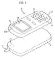
- FIG 1 illustrates a typical mobile telephone or cellphone 1 comprising a main body 5 and an attachable, and in this case also removable, fascia 3.
- the fascia 3 is formed with a user input array 9 which comprises a plurality of holes 11 for engagement with key pads (not shown) provided on the main body 5 of the mobile telephone 1.
- the fascia 3 is also provided with, in this example, a transparent plastics window 13 through which a liquid crystal display (LCD) (not shown in Figure 1) provided on the main body 5 of the mobile telephone 1 can be viewed.
- the mobile telephone 1 also comprises an aerial 7 which allows telecommunication signals to be transmitted and received.
- LCD liquid crystal display
- a passive data storage device 17 Mounted upon, or embedded within, an inside surface of the removable fascia 3 is a passive data storage device 17.
- the fascia 3 will be moulded from a plastics material and the passive data storage device 17 encapsulated in a housing fitted to (for example embedded in or mounted to the surface of) the fascia 3 during the moulding process.
- the main body 5 of the mobile telephone 1 carries a reader unit 15.
- the reader unit 15 is positioned such that, when the fascia 3 is fitted to the main body 5, the passive data storage device 17 will be in range of, as shown will lie adjacent to, the reader unit 15 so that, as will be described in detail below, couplers of the passive data storage device 17 and reader unit 15 couple to enable the passive data storage device 17 to derive a power supply from a signal supplied by the reader unit 15 and, when so activated, to transmit control data contained in its memory.
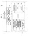
- FIG. 2 shows a functional block diagram of the mobile telephone 1.
- the main body 5 of the mobile telephone 1 comprises: a microphone 33 and a loudspeaker 31 enabling a user to input speech and hear audio output respectively; a user input device 25 (in this case a keyboard) enabling the user to input numbers to be called, other information and instructions for controlling various features of the mobile telephone 1; a display 37 on which incoming or outgoing telephone numbers, SMS text messages and other information can be displayed; and a transceiver 7a which with the aerial 7 shown in Figure 1 enables transmission and reception of communications over a mobile telecommunications network using, for example, the GSM (Global System for Mobile Communications), GPRS (General Packet Radio Service) or 3G (Third Generation, GSM) system, or future such networks.
- GSM Global System for Mobile Communications
- GPRS General Packet Radio Service
- 3G Third Generation
- the above functional components are coupled, via appropriate interfaces (not shown) to a mobile telephone processor 23 which controls the overall operation of the mobile telephone 1.
- the mobile telephone processor 23 is associated with a non-volatile memory 29 which has a read-only portion which contains control operation software data and information data and a writable portion that, for example, enables storage of telephone numbers and messages input to the mobile telephone by the user or received by the mobile telephone over the mobile telecommunications network.
- the mobile telephone 1 further comprises a subscriber identification module (SIM) 27.
- SIM 27 is a detachable module which provides user specific data and also algorithms and data specific to the operator of the mobile telecommunications service provider.
- the mobile telephone processor 23 is coupled to the reader unit 15 via line 23a.
- the reader unit 15 comprises a reader 21 which is coupled to the mobile telephone processor 23 via line 23a and which is also coupled to a first coupling element or coupler LC1 arranged to couple to a similar second coupling element LC2 (see Figure 4) carried by the passive data storage device 17 when the replacement fascia or cover portion 3 is fitted to the main body of the mobile telephone.
- the components of the mobile telephone 1 and the reader unit 15 will be powered by the battery of the mobile telephone 1, although a separate power supply may be provided.
- FIG 3 shows an example of the reader unit 15 which consists of the coupling element or coupler LC1 and the reader 21.
- the reader 21 has a reader microprocessor or microcontroller 51 having a memory 53 which will generally be non-volatile but could be volatile if backed-up, for example battery backed-up.
- An oscillator 43 controlled by an oscillator controller 41 under the control of the reader microprocessor 51 supplies an oscillator output signal to the coupling element LC1.
- the reader microprocessor 51 controls the oscillator control 41 to control activation of the oscillator 43 and, in this example, also controls the oscillator control 41 to interrupt the output of the oscillator 43 to provide a signal from which the data storage device 17 within the fascia 3 can derive a clock signal as will be described below.
- the first coupling element LC1 is also coupled to a demodulator 45 which enables the modulation to be recovered from an amplitude modulated signal.
- the recovered modulation is supplied to signal processor 400 which supplies a digital signal representing a string of binary ones and zeros to the reader microprocessor 51.
- the reader microprocessor 51 communicates with the mobile telephone processor 23 on data line 23a (see Figure 2) so as to affect the functionality or operating characteristics of the mobile telephone.
- FIG 4 shows a simplified block diagram of one example of a passive data storage device forming the detectable component 17.
- the passive data storage device 17 comprises a passive data storage unit 54 and the coupler or coupling element LC2.
- the passive data storage unit 54 consists of a power deriver PD that derives a power supply for the passive data storage unit from the oscillator signal coupled from the reader unit 15 (shown in Figure 3) to the passive data storage device 17 by coupling of the first and second coupling element LC1 and LC2, a data store 59 in the form of a non-volatile memory storing control data for supply to the reader unit 15 and a controller 600 for controlling reading of data from the data store 59 and supply of that data to a modulator M that modulates the oscillating signal inductively coupled to the passive data storage device 17.
- the passive data storage device may include a sensor S for reasons that will be set out below.
- Figures 5 and 6 show, respectively, block diagrams illustrating one example of the reader unit 15 and one example of the passive data storage device 17.
- the passive data storage device 17 and reader unit 15 are adapted to communicate via an inductive coupling and each of the couplers LC1 and LC2 consists of a parallel connection of a capacitor and an inductor C1 and L1 and C2 and L2, respectively.
- the inductive couplers may form a tuned circuit, although this is not necessary at short range.
- the optional sensor S is not shown in Figure 6.
- the demodulator 45 is a simple diode rectifier while the signal processor 400 consists of modulation level and threshold detectors 47 and 49.
- the modulation level detector 47 comprises a comparator 470 and an averaging circuit 471 controlled by the reader microprocessor 51.
- the output from the demodulator 45 is supplied to the positive input of the comparator 470.
- the average of the output of the demodulator 45 is supplied by the averaging circuit 471 to the negative or inverting input of the comparator 470.
- the output of the comparator 470 is supplied to the threshold detector 49 which supplies to the reader microprocessor 51 either a one or a zero, depending upon the relationship between the signal and the threshold.
- the oscillator controller 41 is a logic circuit or a transistor switch which controls the oscillator 43 to switch on or off the carrier signal to the first coupling element LC1 in accordance with a signal received from the reader microprocessor 51 and the averaging circuit 471 generally consists of an averaging capacitor connected between the inverted input of the comparator 470 and ground by a transistor switch or transmission gate which is controlled by the reader microprocessor 51 so as to be conducting while the carrier signal is present and after transients have settled but is off while the carrier is off and during carrier turn-on transients so that averaging is only carried out while there is a steady carrier signal.
- the power deriver PD of the passive data storage unit 54 comprises series-connected diodes D1 and D2 and a capacitor C4 coupled between the coupling element LC2 and a junction J1 between the anode of the diode D1 and a cathode of the diode D2.
- the cathode of the first diode D1 is connected to a first power supply rail P1 (Vdd) while the anode of the second diode D2 is connected to a second power supply rail P2 (Vss).
- the capacitor C4 and the diodes D1 and D2 act effectively as a voltage doubler enabling the peak to peak voltage of a received AC or oscillating signal inductively coupled to the passive data storage device 17 by the coupling elements LC1 and LC2 to be used by the diodes D1 and D2 to derive a power supply for the passive data storage device 17 from the oscillating signal.
- the controller 600 comprises a clock signal deriver 600c in the form of a missing pulse detector which is coupled to the junction J1 to derive a clock signal for the data storage unit 54 from the interrupted oscillator signal supplied by the oscillator 43 and an address counter 600a clocked by the clock signal.
- the controller 600 may also include a reset switch 600b to reset the counter 600a if the passive data storage device 17 is not powered for a predetermined time.
- the controller 600 causes data to be read out from the data store 59 directly to the modulator M which comprises a series-connection of a FET T1 and a capacitor C3 coupled across the capacitor C2 of the coupler LC2.
- an output 59a of the data store 59 is coupled to the gate of the FET T1.
- the data store 59 is a serial read-only memory (ROM). It may, however, be any form of non-volatile memory that does not require battery backup such as a ROM, an EE-PROM (electrically erasable programmable ROM), a flash memory, F-RAM and so on.
- the coupling element LC1 of the passive data storage device 17 lies adjacent and in close proximity to the coupling element LC2 of the reader unit 15, inductively coupling the passive data storage device 17 to the reader unit 15.
- the oscillator 43 of the reader 21 generates a high or RF (radio frequency), typically 13.56MHz (MegaHertz), signal which is supplied to the first coupling element LC1 and inductively coupled to the passive data storage device 17 via the second coupling element LC2.
- the voltage doubler formed by capacitor C4 and diodes D1 and D2 thus derives a power supply for the passive data storage device and, when powered, the clock deriver 600c derives a clock signal from the interrupted oscillator signal and control data is output from the data store 59 on output 59a under the control of the counter 600a.
- control data When control data is output by the data store 59 on the output line 59a, the data switches the FET T1.
- the loading across the inductor L2 varies in dependence upon whether the FET T1 is conducting or non-conducting, causing the oscillating signal to be modulated in accordance with the control data output from the data store 59.
- the control data output from the data store 59 is extracted from the modulated oscillating signal by the demodulator 45, modulation level detector 47, threshold detector 49 and reader microprocessor 51 to provide a data input signal to the mobile telephone processor 23 ( Figures 2 and 3) representing the data output from the data store 59.
- control data output from the data store 59 and downloaded by the reader microprocessor 51 ( Figure 5) to the mobile telephone processor 23 ( Figure 2) may then be stored in the writable portion of the memory 29.
- This control data may comprise at least one of software data, that is computer code executable or implementable by the mobile telephone processor 23, and information data that is stored in the memory 29 so as to be usable by the mobile telephone processor 23.
- the data downloaded from the passive data storage device may include upgrades or modifications of the mobile telephone processor software where the fascia is supplied by or under licence from the manufacturer or supplier of the mobile telephone. Additionally or alternatively, software data may include updates or modifications to existing games software provided with the mobile telephone or new games software.
- Information data may be provided as an alternative to or in addition to software data.
- Examples of information data that may be stored by the data store 59 include dialling or ringing tones and telephone numbers, Internet addresses and/or WAP addresses enabling, for example, the supplier of the fascia to attract buyers by supplying new ringing tones and/or to advertise itself or other companies by supplying their telephone numbers, Internet addresses or WAP addresses.
- Other examples of control data may include graphics data, audio data, image data, video data, biometric data, mobile telephone services, subscription services, network services, promotions, advertisements and so on.
- control data stored by the passive data storage device consists of the actual software and/or information data or the identity or address of the user's mobile network provider or another third party, service provider.
- control data stored by the passive data storage device may be access data that enables the user to access such software and/or information data.
- this access data may consist of a mobile telephone number or a WAP address that the user of the mobile telephone can contact to download new software data and/or information data or the identity or address of the user's mobile network provider or another, third party, service provider.
- downloading of access data may cause the mobile telephone processor 23 to make additional facilities for which the mobile telephone processor is already programmed but that are currently barred from the user available to the user, for example facilities such as international calling access, voicemail and message-taking facilities.
- access data may cause the mobile processor 23 to enable the user to access data previously stored in the memory 29 but not accessible to the user.
- data may include information data such as ringing tones, telephone numbers and/or WAP addresses and software data such as modifications to the processing software of the mobile telephone and/or upgrades or modifications to games software already available to the user or new games software.
- the access data may be, for example, an identity code that enables the mobile telephone processor 23 to identify the particular type of fascia 3 by comparison with data stored in its memory.
- the mobile telephone processor 23 may then control the mobile telephone functionality and capability available to the user in accordance with the identified fascia 3.
- the mobile telephone processor may be programmed so that, if it receives no control data or receives incorrect or non-understandable control data (for example if it receives the wrong access or identity code data), then the mobile telephone processor 23 may determine that the fascia is a counterfeit or unrecognised fascia and may modify or restrict the functionality of the mobile telephone.
- the mobile telephone processor 23 may inhibit access to all or certain optional features or functions and may continue to inhibit use of those optional features or functions until a genuine fascia is fitted to the mobile telephone.
- the mobile telephone processor 23 may simply limit the number of functions available via the mobile telephone, for example the mobile telephone processor 23 may limit the available number of ringing or dialling tones or message taking options, for example, or may "lock" the mobile telephone so that only emergency outgoing calls may be made.
- the passive data storage device is powered and so supplies its stored data to the reader unit 15 whenever the first and second coupling elements LC1 and LC2 are inductively coupled.
- the reader microprocessor may send the received data continually or periodically to the mobile telephone processor 23. Continually powering the passive data storage device 17 may, however, present a drain on the battery of the mobile telephone. Accordingly, the reader microprocessor 51 may be programmed to cause the oscillator control 41 to switch on the oscillator 43 only at predetermined intervals so that the passive data storage device 17 is periodically activated to send its data.
- the passive data storage device 17 is a synchronous passive data storage device, that is the clock signal of the passive data storage device 17 is controlled by and so synchronised with the reader microprocessor 51.
- the passive data storage device 17 may be an asynchronous device, that is the clock deriver 600c coupled to the junction J1 shown in Figure 4 may be replaced by a clock signal generator which is powered up when a power supply is derived by the passive data storage device to generate an independent clock signal for the passive data storage device.
- Figure 6 shows the use of a counter 600a to count out data from the data store 59 it will, of course, be appreciated that the data store 59 may be arranged simply to output its data an address at a time and that the counter 600a may not be necessary.
- the passive data storage device 17 may incorporate a microcontroller that controls read out of data from the data store 59 which may enable different areas of the data store 59 (and so different data) to be accessed and read out in accordance with instructions supplied by the reader microprocessor 51. Such instructions may be transmitted by representing 0 and 1 as long and short duration interruptions of the oscillator signal.
- the passive data storage device modulates the signal received from the reader by, under control of the counter 600a and clock divider 600c, reading data out of the data store 59.
- Figure 7 shows an example of another passive data storage device 17' that may be used in place of the passive data storage device 17 shown in Figure 6.
- This data storage device uses a different controller from that shown in Figure 6.
- the controller comprises a control engine 330 arranged to recognise a number of different codes (in the form of predetermined sequences of ones and zeros) transmitted to it by the reader microprocessor 51.
- the reader microprocessor 51 is arranged to transmit ones and zeros by causing the oscillator control 41 to interrupt the output of the oscillator 43 for short and long durations, respectively.
- a clock signal for the control engine 330 is derived from the signal supplied by the oscillator 43 by a first signal deriver 350 in the form of a fast missing pulse detector coupled to junction J1 while the control engine 330 is arranged to extract the data transmitted by the reader 17' using the output of the first signal deriver 350 and the output of a second signal deriver 360 in the form of a slow missing pulse detector also coupled to the junction J1.
- the timeout periods of the fast and slow missing pulse detectors are set so that the output of the fast missing pulse detector will have one of two widths dependent upon whether the particular data bit is a binary "zero” or a binary "one” while the slow missing pulse detector will provide a pulse only when a particular data bit is a binary "one".
- the control engine 330 can thus determine from the outputs of the first and second signal derivers 350 and 360 whether a received bit is a binary "zero" or a binary "one”. As set out above, the control engine 330 is programmed to enter a number of different states dependent upon the instruction code received from the reader unit 15. These different states may cause the control engine to read out data from different areas of the data store 59.
- the data store 59 may, however, be an electrically erasable memory in which case at least one of the states of the control engine 330 may enable the control engine to erase the data in a portion of the data store 59 and to write new data supplied by the reader unit 15 into the data store 59.
- the mobile telephone processor may be programmed to place a time limit on the availability of the additional functions provided by the data stored in the data store 59.
- control engine 330 is a state machine with its own non-volatile memory it will, of course, be appreciated that the state machine may be replaced by an appropriately programmed microprocessor or microcontroller also having its own memory. Also, different methods for communicating instructions from the reader unit 15 to the control engine 330 may be used.
- the data store 59 may also be used to extend the memory capacity of the mobile telephone to store further telephone numbers and/or other data.
- the passive storage device 17 may also be used to provide a record of historical degree and frequency of use of the mobile telephone. Further details of the writing and reading operations that may be carried out by the control engine 330 are to be found in UK Patent Application number: 0031518.4 ( GB-A-2370462 ) or the corresponding PCT application number GB01/05690 ( WO02/052419 . Data may also be written to the mobile telephone SIM card by the reader unit and mobile telephone processor.
- the actual components of the user interface keypads or keyboard are carried by the main body of the mobile telephone and the fascia 3 simply provides apertures through which the keypads extend.
- the reader unit 15 is, as shown in Figure 2, separate from the main components of the mobile telephone.
- the reader unit 15 may, however, be provided within the main components of the mobile telephone.
- the reader unit may be provided in the SIM card so that it is not necessary to adapt the reader unit for different hardware.
- the passive data storage device 17 uses amplitude modulation to transmit data to the reader unit 15. It will, however, be appreciated that frequency modulation may be used as may phase modulation as described in WO 97/23060 ( PCT/GB96/02975 ).
- the first and second coupling elements are arranged to couple inductively.
- the first and second coupling elements may be arranged to couple in any other manner that requires the first and second coupling elements to be in close proximity but not in physical contact with one another.
- the first and second coupling elements may be arranged to couple capacitively.
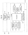
- Figure 8 shows a functional block diagram of another example of a mobile telephone 1" not falling within the scope of the claims wherein the oscillator and oscillator control are omitted from the reader unit and the couplers LC1 and LC2 are tuned to the RF signal emitted by the antenna 7 of the mobile telephone so that the components carried by the fascia 3 derive a power supply from the RF signal transmitted by the mobile telephone and data communication between the passive data storage device 17 and the reader unit is achieved in the manner described above with reference to Figures 6 and 7 by varying the loading of the inductive coupler LC2 to provide an amplitude modulated signal.
- the examples described may be modified so that the mobile phone processor 23 carries out the functions of the reader processor 51 so that, the reader unit 15 need not include the reader processor 51 and reader memory.
- the present invention may be applied to computing devices such as personal computers, PDA (personal digital assistant) or games console with or without facilities for enabling communication over a mobile telecommunications network.
- Figure 9 shows a functional block diagram of a computing device such as a PDA (personal digital assistant) or games console 100 which differs from the mobile telephone shown in Figure 2 in that the SIM card is replaced by a removable disk drive 30 for receiving a removable disk RD, and the transceiver is replaced by a communications interface 38 which may be a MODEM.
- the control data may comprise software data in the form of new software and/or upgrades for existing software provided on the PDA including, for example, games software, wordprocessing, spread sheet and other applications software.
- the control data may alternatively or additionally include information data such as, for example, tunes and images that may be played via the loudspeaker 31 or shown on the display 37 under control of the processor 23.
- the control data may alternatively be in the form of access data that enables the reader unit 15 to instruct the processor 23 where to obtain data represented by the access data by, for example, accessing a particular site on the Internet or another network using the communications interface.
- data may be pre-stored in the memory 29, or available via the communications interface 38.
- the reader unit and data storage device of this computing apparatus may have any of the configurations described above with the mobile telecommunications transceiver being replaced by the communications interface.
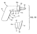
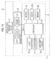
- Figure 10 shows a diagrammatic perspective view of a domestic power tool 60 while Figure 11 shows a functional block diagram of the electrical appliance 60.
- the electrical appliance may be mains or battery powered, having a number of different attachable components comprising or arranged to carry tools for performing different tasks.
- the power tool main body 61 is carrying a replaceable component in the form of a chuck assembly 63 having a chuck 64 for receiving, for example, drill bits or screwdriver heads.
- Figure 10 also shows a further attachable component that may be fitted to the main body 61 of the power tool in place of the chuck assembly.
- the further attachable component 65 is a sander assembly having a sander foot 66 for receiving a sanding sheet 67.
- the main body 61 has an outer plastics, generally moulded, casing. Coupling between the main body 61 and an attachable component 63 or 65 is effected via the drive shaft of a motor (not shown in Figure 10) of the power tool.
- a plastics coupling collar 63a or 65a of the replaceable component is fitted onto a portion of the casing of the main body 61.
- a passive data storage device 17 is fitted to, generally embedded within, the coupling collar 63a or 65a while a reader unit 15 is housed within the casing of the main body together with the other control circuitry of the power tool.
- the reader unit 15 is positioned such that, when the attachable component 63 or 65 is fitted to the main body 61, the passive data storage device 17 will be in range of, as shown will lie adjacent to, the reader unit 15 so that, as will be described in detail below, couplers of the passive data storage device 17 and reader unit 15 couple to enable the passive data storage device 17 to derive a power supply from a signal supplied by the reader unit 15 and, when so activated, to transmit control data contained in its memory.
- the main body 61 comprises, in addition to the reader unit 15, a controller such as a microprocessor or microcontroller 23 which controls the overall operation of the power tool 60.
- the controller 23 may be associated with a non-volatile memory 29 which has a read-only portion which contains control operation software data and information data and a writable portion.
- the controller 23 is coupled to a motor 270 for driving the attachable tool in known manner and also to a user interface 25 consisting of a user input device 72 which will generally, as is known in the art and as shown in Figure 10, consist of an on/off switch 68 and possibly also a speed control 69.
- the user interface may also include one or more indicator lights 80 and a rudimentary loudspeaker 81 that, under control of the controller 23, may issue audible warnings to the user under certain circumstances.
- the power tool 60 is battery operated and the control circuitry 50 in the main body also includes a battery 73. In the interest of simplicity, the couplings between the battery 73 and the various components of the control circuitry, apart from the controller 23, are not shown in Figure 11.
- the reader unit 15 comprises a reader 21 which is coupled to the controller 23 via line 23a and to a first coupler or coupling element LC1.
- the first coupling element LC1 is arranged to couple to a similar second coupling element LC2 (see Figure 4) carried by the passive data storage device 17 when the attachable tool 63 or 65 is fitted to the main body of the appliance.
- the reader unit 15 and the passive data storage device 17 are as described above with reference to Figures 3 to 6.
- the coupling element LC1 of the passive data storage device 17 lies adjacent and in close proximity to the coupling element LC2 of the reader unit 15, inductively coupling the passive data storage device 17 to the reader unit 15 and data is output by the passive data storage device 17 and read by the reader unit as described above with reference to Figures 3 to 6.
- the control data output from the data store 59 is extracted from the modulated oscillating signal by the demodulator 45, modulation level detector 47, threshold detector 49 and reader microprocessor 51 to provide a data input signal to the controller 23 representing the data output from the data store 59.
- control data output from the data store 59 and downloaded by the reader microprocessor 51 to the controller 23 may then be stored in the writable portion of the memory 29.
- This control data may comprise at least one of software data, that is computer code executable or implementable by the controller 23, and information data that is stored in the memory 29 so as to be usable by the controller 23.
- software data the data downloaded from the passive data storage device may include upgrades or modifications of any electrical appliance software where the attachable component is supplied by or under licence from the manufacturer or supplier of the electrical appliance.
- the control data may be, for example, an identity code that enables the controller 23 to identify the particular type of attachable tool by comparison with data stored in its memory. The controller 23 may then control the functionality and capability available to the user in accordance with the attachable tool.
- the controller 23 may control at least one of the speed, drive direction and duration of the operation of the motor 270 in accordance with the control data received by the reader microprocessor.
- the controller 23 may inhibit operation of the electrical appliance if the reader microprocessor receives no control data or receives incorrect or non-understandable control data, for example if the reader microprocessor receives the wrong access or identity code data. This would ensure that, for safety reasons, the electrical appliance is not accidentally operated with an inappropriate tool fitted and for both safety and power saving purposes would ensure that the electrical appliance is not accidentally operated when no tool is attached. Where an incorrect tool is fitted, then the reader microprocessor may cause the controller 23 to cause the warning light 80 to flash or the loudspeaker 81 to emit an audio signal such as an audible warning beep.
- the passive storage device may also be used to provide a record of historical degree and frequency of use of the attachable tool. Further details of the writing and reading operations that may be carried out by the control engine 330 are to be found in UK Patent Application number: 0031518.4 ( GB-A-2370462 ) and the corresponding PCT application Number GB01/05690 ( WO02/052419 ).
- the electronic devices or electrical appliances may be mobile communications devices and other electrical appliances and electronic devices having a microprocessor or microcontroller where a portion or the whole of the housing or a cover of the device is replaceable or where an attachable component such as a tool or a plug-in key or component can be attached to or fitted into or onto the device.
- the electronic device has communications facilities and the data read by the reader unit may be used to communicate with another device, for example to enable payment for a service or product to be effected.
- a unit in the form of a product or ticket vending machine 1000 may carry one or more passive data storage devices 17 each protected by an outer skin or coating of the vending machine housing that enables transmission of a radio frequency signal and so shown in dashed lines in Figure 12.
- Each passive data storage device 17 is associated with a corresponding box 1002 containing a brief description of the corresponding ticket or product. As shown the passive data storage devices are to the side of the boxes. They may however be within the boxes.
- a user 1001 wishes to purchase a product or ticket from the vending machine he brings his portable communications device 1 into close proximity with the data storage device 17 associated with the desired product or ticket to enable the data storage device to derive a power supply and transmit data to the reader unit in the portable communications device.
- the reader unit in the portable communications device supplies the read data to the mobile telephone processor which accesses a location on the communications network identified by the data, for example a service provider which may then debit the user's account and return an authorisation code that when entered by the user using a key pad 1003 causes the vending machine to supply the corresponding required product or ticket to an outlet 1004.
- the unit 1000 may be an advertising hoarding or the like with the passive data storage devices embedded in a cardboard or paper poster.
- the keypad and outlet will of course not be present and the user will be coupled by the mobile telephone transceiver to source of information for example a WAP or website corresponding to a selected passive data storage device.
- the passive data storage device may be associated with images of different products or services, for example.
- Mobile communication devices having reader units as described above may also communicate with one another. Communication by RF or similar electromagnetic frequency has advantages over more sophisticated technology such as BlueTooth TM technology in that the RF communication system is cheaper and is shorter range so that there is less possibility of interference or crosstalk with other devices.
- a reader unit will be able to communicate with a data storage device or other reader unit over a range of up to about six inches.
- BlueTooth TM which uses a frequency of about 2.4 GigaHertz, uses frequency hopping and a large number, typically 82, channels
- RF communication uses a fixed single frequency, typically 13.56 MegaHertz, which provides a continuous signal which is modulated, for example amplitude modulated, by the data to be transmitted.
- such communications do not require the use of an external protocol. All that is required is that the reader unit can demodulate the modulated carrier signal supplied by the data storage device.
- Such a mobile communications device incorporating a reader unit may be used in many forms of commerce, as a payment method, to obtain account details and so on.
Landscapes
- Engineering & Computer Science (AREA)
- Life Sciences & Earth Sciences (AREA)
- Health & Medical Sciences (AREA)
- Physics & Mathematics (AREA)
- Computer Networks & Wireless Communication (AREA)
- General Health & Medical Sciences (AREA)
- Veterinary Medicine (AREA)
- Public Health (AREA)
- Human Computer Interaction (AREA)
- Animal Behavior & Ethology (AREA)
- Surgery (AREA)
- Signal Processing (AREA)
- Biophysics (AREA)
- Pathology (AREA)
- Biomedical Technology (AREA)
- Heart & Thoracic Surgery (AREA)
- Medical Informatics (AREA)
- Molecular Biology (AREA)
- Automation & Control Theory (AREA)
- General Physics & Mathematics (AREA)
- Manufacturing & Machinery (AREA)
- Quality & Reliability (AREA)
- Mechanical Engineering (AREA)
- General Engineering & Computer Science (AREA)
- Telephone Set Structure (AREA)
- Near-Field Transmission Systems (AREA)
- Transceivers (AREA)
- Mobile Radio Communication Systems (AREA)
- Electrotherapy Devices (AREA)
- Developing Agents For Electrophotography (AREA)
- Crystals, And After-Treatments Of Crystals (AREA)
- Selective Calling Equipment (AREA)
- Glass Compositions (AREA)
- Devices For Checking Fares Or Tickets At Control Points (AREA)
- Transition And Organic Metals Composition Catalysts For Addition Polymerization (AREA)
- Telephonic Communication Services (AREA)
- Control Of Vending Devices And Auxiliary Devices For Vending Devices (AREA)
- Telephone Function (AREA)
- Devices For Conveying Motion By Means Of Endless Flexible Members (AREA)
- Reciprocating, Oscillating Or Vibrating Motors (AREA)
Abstract
Description
- This invention relates to a vending system, a vending device for use in a vending system and a portable communications device for use in a vending system, especially a portable communications device such as a telephone arranged to operate using a mobile telecommunications network, and a payment system.
- Telephones that operate using a mobile telecommunications network are variously known as mobile telephones, cellular telephones and cellphones. For simplicity, the term "mobile telephone" will be used hereinafter.
-
WO00/52655 -
WO00/77697 - In one aspect, the present invention provides a vending system as set out in
claim 1. In another aspect, the present invention provides a vending device as set out in claim 12. In another aspect, the present invention provides a portable communications device as set out in claim 16. In another aspect, the present invention provides a payment system as set out in claim 18. - As used herein the term "passive data storage device" means a device that is not self-powered but that derives power from the main body when the fascia is attached to the main body.
- As used herein the term passive detachable element means an element that is not self-powered and that, if it requires a power supply, derives it from the main body when the fascia is attached to the main body.
- The use of a data storage device that does not require its own power supply enables costs to be kept down and, moreover, because such passive data storage devices are relatively cheap to produce and can be incorporated into products relatively easily (for example during a plastics moulding process), the incorporation of the passive data storage device does not add significantly to costs.
- Embodiments of the present invention will now be described, by way of example, with reference to the accompanying drawings, in which:
- Figure 1 shows a diagrammatic perspective view of a mobile telephone with a removable fascia separated from a main body of the mobile telephone;
- Figure 2 shows a functional block diagram of functional components of a mobile telephone, including a reader unit for enabling detection of a replacement fascia;
- Figure 3 shows a functional block diagram of an example of the reader unit shown in Figure 2;
- Figure 4 shows a functional block diagram of an example of a passive data storage device;
- Figure 5 shows a more detailed functional block diagram of an example of the reader unit;
- Figure 6 shows a more detailed functional block diagram of one example of a passive data storage device;
- Figure 7 shows a functional block diagram of another example of a passive data storage device;
- Figure 8 shows a block diagram illustrating an example of a portable communication device not falling within the scope of the claims;
- Figure 9 shows a functional block diagram of computing apparatus such as a personal digital assistant;
- Figure 10 shows a very diagrammatic representation of an electronic device in the form of a power tool having a number of replaceable heads, two of which are shown, one attached to the power tool;
- Figure 11 shows a functional block diagram of functional components of an electrical appliance embodying the invention, including a reader unit for enabling detection of a replacement fascia; and
- Figure 12 shows an example of a vending system.
- Figure 1 illustrates a typical mobile telephone or
cellphone 1 comprising amain body 5 and an attachable, and in this case also removable,fascia 3. Thefascia 3 is formed with auser input array 9 which comprises a plurality ofholes 11 for engagement with key pads (not shown) provided on themain body 5 of themobile telephone 1. Thefascia 3 is also provided with, in this example, atransparent plastics window 13 through which a liquid crystal display (LCD) (not shown in Figure 1) provided on themain body 5 of themobile telephone 1 can be viewed. Themobile telephone 1 also comprises an aerial 7 which allows telecommunication signals to be transmitted and received. - Mounted upon, or embedded within, an inside surface of the
removable fascia 3 is a passivedata storage device 17. Generally, thefascia 3 will be moulded from a plastics material and the passivedata storage device 17 encapsulated in a housing fitted to (for example embedded in or mounted to the surface of) thefascia 3 during the moulding process. - The
main body 5 of themobile telephone 1 carries areader unit 15. Thereader unit 15 is positioned such that, when thefascia 3 is fitted to themain body 5, the passivedata storage device 17 will be in range of, as shown will lie adjacent to, thereader unit 15 so that, as will be described in detail below, couplers of the passivedata storage device 17 andreader unit 15 couple to enable the passivedata storage device 17 to derive a power supply from a signal supplied by thereader unit 15 and, when so activated, to transmit control data contained in its memory. - Figure 2 shows a functional block diagram of the
mobile telephone 1. Themain body 5 of themobile telephone 1 comprises: amicrophone 33 and aloudspeaker 31 enabling a user to input speech and hear audio output respectively; a user input device 25 (in this case a keyboard) enabling the user to input numbers to be called, other information and instructions for controlling various features of themobile telephone 1; adisplay 37 on which incoming or outgoing telephone numbers, SMS text messages and other information can be displayed; and atransceiver 7a which with the aerial 7 shown in Figure 1 enables transmission and reception of communications over a mobile telecommunications network using, for example, the GSM (Global System for Mobile Communications), GPRS (General Packet Radio Service) or 3G (Third Generation, GSM) system, or future such networks. - The above functional components are coupled, via appropriate interfaces (not shown) to a
mobile telephone processor 23 which controls the overall operation of themobile telephone 1. Themobile telephone processor 23 is associated with anon-volatile memory 29 which has a read-only portion which contains control operation software data and information data and a writable portion that, for example, enables storage of telephone numbers and messages input to the mobile telephone by the user or received by the mobile telephone over the mobile telecommunications network. - As is known in the art, the
mobile telephone 1 further comprises a subscriber identification module (SIM) 27. TheSIM 27 is a detachable module which provides user specific data and also algorithms and data specific to the operator of the mobile telecommunications service provider. Themobile telephone processor 23 is coupled to thereader unit 15 vialine 23a. - The
reader unit 15 comprises areader 21 which is coupled to themobile telephone processor 23 vialine 23a and which is also coupled to a first coupling element or coupler LC1 arranged to couple to a similar second coupling element LC2 (see Figure 4) carried by the passivedata storage device 17 when the replacement fascia orcover portion 3 is fitted to the main body of the mobile telephone. - Although not shown in Figure 2, it will be appreciated that the components of the
mobile telephone 1 and thereader unit 15 will be powered by the battery of themobile telephone 1, although a separate power supply may be provided. - Figure 3 shows an example of the
reader unit 15 which consists of the coupling element or coupler LC1 and thereader 21. Thereader 21 has a reader microprocessor ormicrocontroller 51 having amemory 53 which will generally be non-volatile but could be volatile if backed-up, for example battery backed-up. Anoscillator 43 controlled by anoscillator controller 41 under the control of thereader microprocessor 51 supplies an oscillator output signal to the coupling element LC1. Thereader microprocessor 51 controls theoscillator control 41 to control activation of theoscillator 43 and, in this example, also controls theoscillator control 41 to interrupt the output of theoscillator 43 to provide a signal from which thedata storage device 17 within thefascia 3 can derive a clock signal as will be described below. - The first coupling element LC1 is also coupled to a
demodulator 45 which enables the modulation to be recovered from an amplitude modulated signal. The recovered modulation is supplied tosignal processor 400 which supplies a digital signal representing a string of binary ones and zeros to thereader microprocessor 51. In response to receipt of control data from the passive data storage device, thereader microprocessor 51 communicates with themobile telephone processor 23 ondata line 23a (see Figure 2) so as to affect the functionality or operating characteristics of the mobile telephone. - Figure 4 shows a simplified block diagram of one example of a passive data storage device forming the
detectable component 17. As shown, the passivedata storage device 17 comprises a passivedata storage unit 54 and the coupler or coupling element LC2. The passivedata storage unit 54 consists of a power deriver PD that derives a power supply for the passive data storage unit from the oscillator signal coupled from the reader unit 15 (shown in Figure 3) to the passivedata storage device 17 by coupling of the first and second coupling element LC1 and LC2, adata store 59 in the form of a non-volatile memory storing control data for supply to thereader unit 15 and acontroller 600 for controlling reading of data from thedata store 59 and supply of that data to a modulator M that modulates the oscillating signal inductively coupled to the passivedata storage device 17. Optionally, the passive data storage device may include a sensor S for reasons that will be set out below. - Figures 5 and 6 show, respectively, block diagrams illustrating one example of the
reader unit 15 and one example of the passivedata storage device 17. In this example, the passivedata storage device 17 andreader unit 15 are adapted to communicate via an inductive coupling and each of the couplers LC1 and LC2 consists of a parallel connection of a capacitor and an inductor C1 and L1 and C2 and L2, respectively. The inductive couplers may form a tuned circuit, although this is not necessary at short range. The optional sensor S is not shown in Figure 6. - In the example shown in Figure 5, the
demodulator 45 is a simple diode rectifier while thesignal processor 400 consists of modulation level andthreshold detectors 47 and 49. The modulation level detector 47 comprises acomparator 470 and anaveraging circuit 471 controlled by thereader microprocessor 51. The output from thedemodulator 45 is supplied to the positive input of thecomparator 470. The average of the output of thedemodulator 45 is supplied by theaveraging circuit 471 to the negative or inverting input of thecomparator 470. - The output of the
comparator 470 is supplied to thethreshold detector 49 which supplies to thereader microprocessor 51 either a one or a zero, depending upon the relationship between the signal and the threshold. - In this example, the
oscillator controller 41 is a logic circuit or a transistor switch which controls theoscillator 43 to switch on or off the carrier signal to the first coupling element LC1 in accordance with a signal received from thereader microprocessor 51 and the averagingcircuit 471 generally consists of an averaging capacitor connected between the inverted input of thecomparator 470 and ground by a transistor switch or transmission gate which is controlled by thereader microprocessor 51 so as to be conducting while the carrier signal is present and after transients have settled but is off while the carrier is off and during carrier turn-on transients so that averaging is only carried out while there is a steady carrier signal. - As shown in Figure 6, the power deriver PD of the passive
data storage unit 54 comprises series-connected diodes D1 and D2 and a capacitor C4 coupled between the coupling element LC2 and a junction J1 between the anode of the diode D1 and a cathode of the diode D2. The cathode of the first diode D1 is connected to a first power supply rail P1 (Vdd) while the anode of the second diode D2 is connected to a second power supply rail P2 (Vss). The capacitor C4 and the diodes D1 and D2 act effectively as a voltage doubler enabling the peak to peak voltage of a received AC or oscillating signal inductively coupled to the passivedata storage device 17 by the coupling elements LC1 and LC2 to be used by the diodes D1 and D2 to derive a power supply for the passivedata storage device 17 from the oscillating signal. - It will, of course, be appreciated that, in the interests of simplicity, the power supply connections to the remaining components of the passive
data storage device 17 are not shown in Figure 6. - In this example, the
controller 600 comprises aclock signal deriver 600c in the form of a missing pulse detector which is coupled to the junction J1 to derive a clock signal for thedata storage unit 54 from the interrupted oscillator signal supplied by theoscillator 43 and anaddress counter 600a clocked by the clock signal. Thecontroller 600 may also include areset switch 600b to reset thecounter 600a if the passivedata storage device 17 is not powered for a predetermined time. - In this example, the
controller 600 causes data to be read out from thedata store 59 directly to the modulator M which comprises a series-connection of a FET T1 and a capacitor C3 coupled across the capacitor C2 of the coupler LC2. Thus, anoutput 59a of thedata store 59 is coupled to the gate of the FET T1. In this example, thedata store 59 is a serial read-only memory (ROM). It may, however, be any form of non-volatile memory that does not require battery backup such as a ROM, an EE-PROM (electrically erasable programmable ROM), a flash memory, F-RAM and so on. - When, as shown in Figure 1, the
replaceable fascia 3 is fitted to themain body 5 of themobile telephone 1 the coupling element LC1 of the passivedata storage device 17 lies adjacent and in close proximity to the coupling element LC2 of thereader unit 15, inductively coupling the passivedata storage device 17 to thereader unit 15. Theoscillator 43 of thereader 21 generates a high or RF (radio frequency), typically 13.56MHz (MegaHertz), signal which is supplied to the first coupling element LC1 and inductively coupled to the passivedata storage device 17 via the second coupling element LC2. The voltage doubler formed by capacitor C4 and diodes D1 and D2 thus derives a power supply for the passive data storage device and, when powered, theclock deriver 600c derives a clock signal from the interrupted oscillator signal and control data is output from thedata store 59 onoutput 59a under the control of thecounter 600a. - When control data is output by the
data store 59 on theoutput line 59a, the data switches the FET T1. The loading across the inductor L2 varies in dependence upon whether the FET T1 is conducting or non-conducting, causing the oscillating signal to be modulated in accordance with the control data output from thedata store 59. - The control data output from the
data store 59 is extracted from the modulated oscillating signal by thedemodulator 45, modulation level detector 47,threshold detector 49 andreader microprocessor 51 to provide a data input signal to the mobile telephone processor 23 (Figures 2 and 3) representing the data output from thedata store 59. - The control data output from the
data store 59 and downloaded by the reader microprocessor 51 (Figure 5) to the mobile telephone processor 23 (Figure 2) may then be stored in the writable portion of thememory 29. This control data may comprise at least one of software data, that is computer code executable or implementable by themobile telephone processor 23, and information data that is stored in thememory 29 so as to be usable by themobile telephone processor 23. As an example of software data, the data downloaded from the passive data storage device may include upgrades or modifications of the mobile telephone processor software where the fascia is supplied by or under licence from the manufacturer or supplier of the mobile telephone. Additionally or alternatively, software data may include updates or modifications to existing games software provided with the mobile telephone or new games software. - Information data may be provided as an alternative to or in addition to software data. Examples of information data that may be stored by the
data store 59 include dialling or ringing tones and telephone numbers, Internet addresses and/or WAP addresses enabling, for example, the supplier of the fascia to attract buyers by supplying new ringing tones and/or to advertise itself or other companies by supplying their telephone numbers, Internet addresses or WAP addresses. Other examples of control data may include graphics data, audio data, image data, video data, biometric data, mobile telephone services, subscription services, network services, promotions, advertisements and so on. - As described above, the control data stored by the passive data storage device consists of the actual software and/or information data or the identity or address of the user's mobile network provider or another third party, service provider. As another possibility, the control data stored by the passive data storage device may be access data that enables the user to access such software and/or information data. For example, this access data may consist of a mobile telephone number or a WAP address that the user of the mobile telephone can contact to download new software data and/or information data or the identity or address of the user's mobile network provider or another, third party, service provider. As another possibility, downloading of access data may cause the
mobile telephone processor 23 to make additional facilities for which the mobile telephone processor is already programmed but that are currently barred from the user available to the user, for example facilities such as international calling access, voicemail and message-taking facilities. As a further possibility, such access data may cause themobile processor 23 to enable the user to access data previously stored in thememory 29 but not accessible to the user. Such data may include information data such as ringing tones, telephone numbers and/or WAP addresses and software data such as modifications to the processing software of the mobile telephone and/or upgrades or modifications to games software already available to the user or new games software. - The access data may be, for example, an identity code that enables the
mobile telephone processor 23 to identify the particular type offascia 3 by comparison with data stored in its memory. Themobile telephone processor 23 may then control the mobile telephone functionality and capability available to the user in accordance with the identifiedfascia 3. - The mobile telephone processor may be programmed so that, if it receives no control data or receives incorrect or non-understandable control data (for example if it receives the wrong access or identity code data), then the
mobile telephone processor 23 may determine that the fascia is a counterfeit or unrecognised fascia and may modify or restrict the functionality of the mobile telephone. Themobile telephone processor 23 may inhibit access to all or certain optional features or functions and may continue to inhibit use of those optional features or functions until a genuine fascia is fitted to the mobile telephone. For example, if themobile telephone processor 23 determines that the fascia is a counterfeit fascia, then themobile telephone processor 23 may simply limit the number of functions available via the mobile telephone, for example themobile telephone processor 23 may limit the available number of ringing or dialling tones or message taking options, for example, or may "lock" the mobile telephone so that only emergency outgoing calls may be made. - As described above, the passive data storage device is powered and so supplies its stored data to the
reader unit 15 whenever the first and second coupling elements LC1 and LC2 are inductively coupled. The reader microprocessor may send the received data continually or periodically to themobile telephone processor 23. Continually powering the passivedata storage device 17 may, however, present a drain on the battery of the mobile telephone. Accordingly, thereader microprocessor 51 may be programmed to cause theoscillator control 41 to switch on theoscillator 43 only at predetermined intervals so that the passivedata storage device 17 is periodically activated to send its data. - As described above, the passive
data storage device 17 is a synchronous passive data storage device, that is the clock signal of the passivedata storage device 17 is controlled by and so synchronised with thereader microprocessor 51. However, the passivedata storage device 17 may be an asynchronous device, that is theclock deriver 600c coupled to the junction J1 shown in Figure 4 may be replaced by a clock signal generator which is powered up when a power supply is derived by the passive data storage device to generate an independent clock signal for the passive data storage device. Also, although Figure 6 shows the use of a counter 600a to count out data from thedata store 59 it will, of course, be appreciated that thedata store 59 may be arranged simply to output its data an address at a time and that thecounter 600a may not be necessary. In addition, the passivedata storage device 17 may incorporate a microcontroller that controls read out of data from thedata store 59 which may enable different areas of the data store 59 (and so different data) to be accessed and read out in accordance with instructions supplied by thereader microprocessor 51. Such instructions may be transmitted by representing 0 and 1 as long and short duration interruptions of the oscillator signal. - As described above, the passive data storage device modulates the signal received from the reader by, under control of the
counter 600a andclock divider 600c, reading data out of thedata store 59. - Figure 7 shows an example of another passive data storage device 17' that may be used in place of the passive
data storage device 17 shown in Figure 6. This data storage device uses a different controller from that shown in Figure 6. In this case, the controller comprises acontrol engine 330 arranged to recognise a number of different codes (in the form of predetermined sequences of ones and zeros) transmitted to it by thereader microprocessor 51. In this example, thereader microprocessor 51 is arranged to transmit ones and zeros by causing theoscillator control 41 to interrupt the output of theoscillator 43 for short and long durations, respectively. - In this example, a clock signal for the
control engine 330 is derived from the signal supplied by theoscillator 43 by afirst signal deriver 350 in the form of a fast missing pulse detector coupled to junction J1 while thecontrol engine 330 is arranged to extract the data transmitted by the reader 17' using the output of thefirst signal deriver 350 and the output of asecond signal deriver 360 in the form of a slow missing pulse detector also coupled to the junction J1. - The timeout periods of the fast and slow missing pulse detectors are set so that the output of the fast missing pulse detector will have one of two widths dependent upon whether the particular data bit is a binary "zero" or a binary "one" while the slow missing pulse detector will provide a pulse only when a particular data bit is a binary "one". The
control engine 330 can thus determine from the outputs of the first andsecond signal derivers control engine 330 is programmed to enter a number of different states dependent upon the instruction code received from thereader unit 15. These different states may cause the control engine to read out data from different areas of thedata store 59. Thedata store 59 may, however, be an electrically erasable memory in which case at least one of the states of thecontrol engine 330 may enable the control engine to erase the data in a portion of thedata store 59 and to write new data supplied by thereader unit 15 into thedata store 59. This would enable, for example, thereader unit 15 to overwrite at least a part of the content of thedata store 59 after thefascia 3 has first been coupled to themain body 5 so as to limit or inhibit access to the functionality provided by the data stored in thedata store 59 if the fascia is subsequently removed and fitted to a different mobile telephone. As another possibility, the mobile telephone processor may be programmed to place a time limit on the availability of the additional functions provided by the data stored in thedata store 59. - Although as described above, the
control engine 330 is a state machine with its own non-volatile memory it will, of course, be appreciated that the state machine may be replaced by an appropriately programmed microprocessor or microcontroller also having its own memory. Also, different methods for communicating instructions from thereader unit 15 to thecontrol engine 330 may be used. - Where, as described above, the
data store 59 is writable, then it may also be used to extend the memory capacity of the mobile telephone to store further telephone numbers and/or other data. Thepassive storage device 17 may also be used to provide a record of historical degree and frequency of use of the mobile telephone. Further details of the writing and reading operations that may be carried out by thecontrol engine 330 are to be found inUK Patent Application number: 0031518.4 GB-A-2370462 PCT application number GB01/05690 WO02/052419 - As described above, the actual components of the user interface keypads or keyboard are carried by the main body of the mobile telephone and the
fascia 3 simply provides apertures through which the keypads extend. - As described above, the
reader unit 15 is, as shown in Figure 2, separate from the main components of the mobile telephone. Thereader unit 15 may, however, be provided within the main components of the mobile telephone. For example, the reader unit may be provided in the SIM card so that it is not necessary to adapt the reader unit for different hardware. - As described above, the passive
data storage device 17 uses amplitude modulation to transmit data to thereader unit 15. It will, however, be appreciated that frequency modulation may be used as may phase modulation as described inWO 97/23060 PCT/GB96/02975 - As described above, the first and second coupling elements are arranged to couple inductively. The first and second coupling elements may be arranged to couple in any other manner that requires the first and second coupling elements to be in close proximity but not in physical contact with one another. For example, the first and second coupling elements may be arranged to couple capacitively. These non contact arrangements have advantages over ohmic coupling arrangements because the use of ohmic coupling has the disadvantage that actual electrical contact needs to be established between the first and second coupling elements and that this requires the coupling elements to be exposed which may make manufacture of the
fascia 3 more difficult and repeated removal and fitting of fascias may cause wear and tear of the coupling elements. Also, both capacitive and ohmic coupling require more accurate alignment and closer positioning of the first and second coupling elements than inductive coupling. Other forms of coupling, such as an optical coupling, may also be used. - Figure 8 shows a functional block diagram of another example of a
mobile telephone 1" not falling within the scope of the claims wherein the oscillator and oscillator control are omitted from the reader unit and the couplers LC1 and LC2 are tuned to the RF signal emitted by theantenna 7 of the mobile telephone so that the components carried by thefascia 3 derive a power supply from the RF signal transmitted by the mobile telephone and data communication between the passivedata storage device 17 and the reader unit is achieved in the manner described above with reference to Figures 6 and 7 by varying the loading of the inductive coupler LC2 to provide an amplitude modulated signal. - The examples described may be modified so that the
mobile phone processor 23 carries out the functions of thereader processor 51 so that, thereader unit 15 need not include thereader processor 51 and reader memory. - The present invention may be applied to computing devices such as personal computers, PDA (personal digital assistant) or games console with or without facilities for enabling communication over a mobile telecommunications network. Figure 9 shows a functional block diagram of a computing device such as a PDA (personal digital assistant) or
games console 100 which differs from the mobile telephone shown in Figure 2 in that the SIM card is replaced by aremovable disk drive 30 for receiving a removable disk RD, and the transceiver is replaced by a communications interface 38 which may be a MODEM. In this case, the control data may comprise software data in the form of new software and/or upgrades for existing software provided on the PDA including, for example, games software, wordprocessing, spread sheet and other applications software. The control data may alternatively or additionally include information data such as, for example, tunes and images that may be played via theloudspeaker 31 or shown on thedisplay 37 under control of theprocessor 23. As described above, the control data may alternatively be in the form of access data that enables thereader unit 15 to instruct theprocessor 23 where to obtain data represented by the access data by, for example, accessing a particular site on the Internet or another network using the communications interface. Such data may be pre-stored in thememory 29, or available via the communications interface 38. The reader unit and data storage device of this computing apparatus may have any of the configurations described above with the mobile telecommunications transceiver being replaced by the communications interface. - Examples, not falling within the claims, will now be described of electronic devices or electrical appliances having an attachable functional component such as, for example, a replaceable tool will be described.
- Figure 10 shows a diagrammatic perspective view of a
domestic power tool 60 while Figure 11 shows a functional block diagram of theelectrical appliance 60. The electrical appliance may be mains or battery powered, having a number of different attachable components comprising or arranged to carry tools for performing different tasks. As shown in Figure 10, the power toolmain body 61 is carrying a replaceable component in the form of achuck assembly 63 having achuck 64 for receiving, for example, drill bits or screwdriver heads. Figure 10 also shows a further attachable component that may be fitted to themain body 61 of the power tool in place of the chuck assembly. In the example shown, the furtherattachable component 65 is a sander assembly having asander foot 66 for receiving asanding sheet 67. - In the case of this power tool, the
main body 61 has an outer plastics, generally moulded, casing. Coupling between themain body 61 and anattachable component attachable component plastics coupling collar main body 61. A passivedata storage device 17 is fitted to, generally embedded within, thecoupling collar reader unit 15 is housed within the casing of the main body together with the other control circuitry of the power tool. - The
reader unit 15 is positioned such that, when theattachable component main body 61, the passivedata storage device 17 will be in range of, as shown will lie adjacent to, thereader unit 15 so that, as will be described in detail below, couplers of the passivedata storage device 17 andreader unit 15 couple to enable the passivedata storage device 17 to derive a power supply from a signal supplied by thereader unit 15 and, when so activated, to transmit control data contained in its memory. - As can be seen from Figures 10 and 11, the
main body 61 comprises, in addition to thereader unit 15, a controller such as a microprocessor ormicrocontroller 23 which controls the overall operation of thepower tool 60. Thecontroller 23 may be associated with anon-volatile memory 29 which has a read-only portion which contains control operation software data and information data and a writable portion. Thecontroller 23 is coupled to amotor 270 for driving the attachable tool in known manner and also to auser interface 25 consisting of auser input device 72 which will generally, as is known in the art and as shown in Figure 10, consist of an on/offswitch 68 and possibly also aspeed control 69. The user interface may also include one or more indicator lights 80 and arudimentary loudspeaker 81 that, under control of thecontroller 23, may issue audible warnings to the user under certain circumstances. In this example, thepower tool 60 is battery operated and thecontrol circuitry 50 in the main body also includes abattery 73. In the interest of simplicity, the couplings between thebattery 73 and the various components of the control circuitry, apart from thecontroller 23, are not shown in Figure 11. - As described earlier, the
reader unit 15 comprises areader 21 which is coupled to thecontroller 23 vialine 23a and to a first coupler or coupling element LC1. The first coupling element LC1 is arranged to couple to a similar second coupling element LC2 (see Figure 4) carried by the passivedata storage device 17 when theattachable tool reader unit 15 and the passivedata storage device 17 are as described above with reference to Figures 3 to 6. - When the attachable component is fitted to the main body of the electrical appliance the coupling element LC1 of the passive
data storage device 17 lies adjacent and in close proximity to the coupling element LC2 of thereader unit 15, inductively coupling the passivedata storage device 17 to thereader unit 15 and data is output by the passivedata storage device 17 and read by the reader unit as described above with reference to Figures 3 to 6. - The control data output from the
data store 59 is extracted from the modulated oscillating signal by thedemodulator 45, modulation level detector 47,threshold detector 49 andreader microprocessor 51 to provide a data input signal to thecontroller 23 representing the data output from thedata store 59. - The control data output from the
data store 59 and downloaded by thereader microprocessor 51 to thecontroller 23 may then be stored in the writable portion of thememory 29. This control data may comprise at least one of software data, that is computer code executable or implementable by thecontroller 23, and information data that is stored in thememory 29 so as to be usable by thecontroller 23. As an example of software data, the data downloaded from the passive data storage device may include upgrades or modifications of any electrical appliance software where the attachable component is supplied by or under licence from the manufacturer or supplier of the electrical appliance. - The control data may be, for example, an identity code that enables the
controller 23 to identify the particular type of attachable tool by comparison with data stored in its memory. Thecontroller 23 may then control the functionality and capability available to the user in accordance with the attachable tool. - As an example, the
controller 23 may control at least one of the speed, drive direction and duration of the operation of themotor 270 in accordance with the control data received by the reader microprocessor. Alternatively or additionally, thecontroller 23 may inhibit operation of the electrical appliance if the reader microprocessor receives no control data or receives incorrect or non-understandable control data, for example if the reader microprocessor receives the wrong access or identity code data. This would ensure that, for safety reasons, the electrical appliance is not accidentally operated with an inappropriate tool fitted and for both safety and power saving purposes would ensure that the electrical appliance is not accidentally operated when no tool is attached. Where an incorrect tool is fitted, then the reader microprocessor may cause thecontroller 23 to cause thewarning light 80 to flash or theloudspeaker 81 to emit an audio signal such as an audible warning beep. - Where, as described above, the
data store 59 is writable, then the passive storage device may also be used to provide a record of historical degree and frequency of use of the attachable tool. Further details of the writing and reading operations that may be carried out by thecontrol engine 330 are to be found inUK Patent Application number: 0031518.4 GB-A-2370462 PCT application Number GB01/05690 WO02/052419 - The electronic devices or electrical appliances may be mobile communications devices and other electrical appliances and electronic devices having a microprocessor or microcontroller where a portion or the whole of the housing or a cover of the device is replaceable or where an attachable component such as a tool or a plug-in key or component can be attached to or fitted into or onto the device.
- In embodiments of the present invention, the electronic device has communications facilities and the data read by the reader unit may be used to communicate with another device, for example to enable payment for a service or product to be effected. Thus, in one embodiment of the invention as shown very schematically in Figure 12, a unit in the form of a product or
ticket vending machine 1000 may carry one or more passivedata storage devices 17 each protected by an outer skin or coating of the vending machine housing that enables transmission of a radio frequency signal and so shown in dashed lines in Figure 12. Each passivedata storage device 17 is associated with acorresponding box 1002 containing a brief description of the corresponding ticket or product. As shown the passive data storage devices are to the side of the boxes. They may however be within the boxes. When auser 1001 wishes to purchase a product or ticket from the vending machine he brings hisportable communications device 1 into close proximity with thedata storage device 17 associated with the desired product or ticket to enable the data storage device to derive a power supply and transmit data to the reader unit in the portable communications device. The reader unit in the portable communications device supplies the read data to the mobile telephone processor which accesses a location on the communications network identified by the data, for example a service provider which may then debit the user's account and return an authorisation code that when entered by the user using akey pad 1003 causes the vending machine to supply the corresponding required product or ticket to anoutlet 1004. - Instead of being a vending machine, the
unit 1000 may be an advertising hoarding or the like with the passive data storage devices embedded in a cardboard or paper poster. In this case, the keypad and outlet will of course not be present and the user will be coupled by the mobile telephone transceiver to source of information for example a WAP or website corresponding to a selected passive data storage device. In this case, the passive data storage device may be associated with images of different products or services, for example. - Mobile communication devices having reader units as described above may also communicate with one another. Communication by RF or similar electromagnetic frequency has advantages over more sophisticated technology such as BlueTooth™ technology in that the RF communication system is cheaper and is shorter range so that there is less possibility of interference or crosstalk with other devices. Typically a reader unit will be able to communicate with a data storage device or other reader unit over a range of up to about six inches. Also, in contrast to BlueTooth™ which uses a frequency of about 2.4 GigaHertz, uses frequency hopping and a large number, typically 82, channels, RF communication uses a fixed single frequency, typically 13.56 MegaHertz, which provides a continuous signal which is modulated, for example amplitude modulated, by the data to be transmitted. In addition, unlike BlueTooth™, such communications do not require the use of an external protocol. All that is required is that the reader unit can demodulate the modulated carrier signal supplied by the data storage device.
- Such a mobile communications device incorporating a reader unit may be used in many forms of commerce, as a payment method, to obtain account details and so on.
Claims (19)
- A vending system comprising:a vending device for enabling at least one product or at least one item relating to a product or service to be supplied to a user, the vending device carrying passive data storage means having a memory storing data relating to the at least one product or service; and a portable communications device having communication means for communicating over a network and signal supplying means for supplying a carrier signal, the passive data storage means carried by the vending device having power deriving means for deriving a power supply for the passive data storage means from the carrier signal when the portable communications device is in the vicinity of the passive data storage means and modulation means for modulating the carrier signal in accordance with data read from the memory in response to derivation of a power supply by the power supply deriving means, the portable communications device having data extracting means for extracting data from a modulated carrier signal and control means operable to enable the user to be supplied with the at least one product or the at least one item relating to a product or service.
- A vending system according to claim 1, wherein the control means is operable to cause the communications means to access a location on the network identified by data extracted by the data extracting means to enable the user to be supplied with the at least one product or the at least one item relating to a product or service.
- A vending system according to claim 1 or 2, wherein the vending device has a user input for enabling a user to input authorisation data to enable the vending of the at least one product or the at least one item relating to a product or service.
- A vending system according to claim 1 or 2, wherein the vending device has a user input for enabling a user to input authorisation data received by the communications means to enable the vending of the product or the at least one item relating to a product or service.
- A vending system according to claim 2, 3 or 4, wherein the location on the network is associated with a service provider and wherein the service provider is operable to debit an account in response to the communications means accessing the location on the network.
- A vending system according to any of the preceding claims, wherein the vending device has a vending outlet for supplying the at least one product or the at least one item relating to a product or service directly to the user.
- A vending system according to any of the preceding claims, wherein the vending device carries plural passive data storage devices each associated with a different product or service.
- A vending system according to any of the preceding claims, wherein the vending device has a user interface presenting to the user information relating to the or each product or service.
- A vending system according to any of claims 1 to 6, wherein the vending device carries plural passive data storage devices each associated with a different product or service and the vending device has a respective description of the corresponding product or service associated with each passive data storage device.
- A vending system according to any of the preceding claims, wherein the portable communications device comprises at least one of a mobile telephone and a personal digital assistant.
- A vending system according to any of the preceding claims, wherein the passive data storage means and the portable communications device are operable to couple inductively when the portable communications device is in the vicinity of the passive data storage means.
- A vending device for use in a vending system according to claim 1 for enabling at least one product or at least one item relating to a product or service to be supplied to a user, the vending device carrying passive data storage means having a memory storing data relating to the at least one product or service, the passive data storage means carried by the vending device having power deriving means for deriving a power supply for the passive data storage means from a carrier signal supplied by signal supplying means of a portable communications device when the portable communications device is in the vicinity of the passive data storage means and modulation means for modulating the carrier signal in accordance with data read from the memory in response to derivation of a power supply by the power supply deriving means so as to enable the read data to be communicated to the portable communications device, the vending device having vending means operable to enable the user to be supplied with the at least one product or the at least one item relating to a product or service.
- A vending device according to claim 12, wherein the supply of the at least one product or the at least one item relating to a product or service is in response to authorisation data received by a network communication means of the portable communications device from a location on the network identified by data read from the memory.
- A vending device according to claim 12 or 13, wherein the vending means comprises a user input for enabling a user to input authorisation data received by the communication means to enable the vending of the at least one product or service.
- A vending system according to claim 12, 13 or 14, wherein the vending means has a vending outlet for supplying the at least one product or the at least one item relating to a product or service to the user in response to authorisation data received by the communication means.
- A portable communications device for use in a vending system according to claim 1 comprising a vending device carrying passive data storage means having a memory storing data relating to the at least one product or service, the portable communications device having communication means for communicating over a network and signal supplying means for supplying a carrier signal which, when the portable communications device is in the vicinity of the passive data storage means, causes power deriving means of the passive data storage means to derive a power supply from the carrier signal and to modulate the carrier signal in accordance with data read from the memory, the portable communications device also having data extracting means for extracting data from a modulated carrier to enable the user to be supplied with the at least one product or service.
- A portable communications device for use in a vending system according to claim 16, wherein the portable communications device comprises control means for causing the communication means to access a location on the network identified by the data extracted by the data extracting means to enable the user to be supplied with the at least one product or the at least one item relating to a product or service in response to authorisation data received by the communication means.
- A payment system comprising a portable communications device having communication means for communicating over a network and signal supplying means for supplying a carrier signal which, when the portable communications device is in the vicinity of passive data storage means, causes power deriving means of the passive data storage means to derive a power supply from the carrier signal and the passive data storage means to modulate the carrier signal in accordance with data read from a memory of the passive data storage means, the portable communications device also having data extracting means for extracting data from a modulated carrier signal and control means operable to use data extracted by the data extracting means to enable payment for at least one product or service to be effected by the portable communications device.
- A payment system according to claim 18, wherein the control means operable to use data extracted by the data extracting means to enable the communications means to access a location on the network to enable payment to be effected.
Applications Claiming Priority (9)
| Application Number | Priority Date | Filing Date | Title |
|---|---|---|---|
| GB0111722 | 2001-05-14 | ||
| GBGB0111722.5A GB0111722D0 (en) | 2001-05-14 | 2001-05-14 | Component identification |
| GB0129491 | 2001-12-10 | ||
| GB0129490 | 2001-12-10 | ||
| GB0129491A GB2376758A (en) | 2001-05-14 | 2001-12-10 | Electronic or electrical device and attachable components therefor |
| GB0129490A GB2375693A (en) | 2001-05-14 | 2001-12-10 | Replaceable fascia for a portable communications device |
| GB0208275 | 2002-04-10 | ||
| GB0208275A GB0208275D0 (en) | 2001-05-14 | 2002-04-10 | Fascias |
| EP02769514A EP1393533B1 (en) | 2001-05-14 | 2002-05-14 | Electrical devices |
Related Parent Applications (1)
| Application Number | Title | Priority Date | Filing Date |
|---|---|---|---|
| EP02769514A Division EP1393533B1 (en) | 2001-05-14 | 2002-05-14 | Electrical devices |
Publications (3)
| Publication Number | Publication Date |
|---|---|
| EP1599024A2 EP1599024A2 (en) | 2005-11-23 |
| EP1599024A3 EP1599024A3 (en) | 2006-03-22 |
| EP1599024B1 true EP1599024B1 (en) | 2007-07-25 |
Family
ID=9914585
Family Applications (6)
| Application Number | Title | Priority Date | Filing Date |
|---|---|---|---|
| EP04076968A Expired - Lifetime EP1471717B1 (en) | 2001-05-14 | 2002-05-14 | A portable communication device |
| EP10181526A Withdrawn EP2290926A3 (en) | 2001-05-14 | 2002-05-14 | Portable electrical device |
| EP05076636A Expired - Lifetime EP1599024B1 (en) | 2001-05-14 | 2002-05-14 | Portable communication device for use in a vending system |
| EP05076635A Withdrawn EP1599023A3 (en) | 2001-05-14 | 2002-05-14 | Portable communication device |
| EP05076637A Expired - Lifetime EP1599025B1 (en) | 2001-05-14 | 2002-05-14 | Portable communication device |
| EP05012004A Withdrawn EP1569352A3 (en) | 2001-05-14 | 2002-05-14 | Electrical devices |
Family Applications Before (2)
| Application Number | Title | Priority Date | Filing Date |
|---|---|---|---|
| EP04076968A Expired - Lifetime EP1471717B1 (en) | 2001-05-14 | 2002-05-14 | A portable communication device |
| EP10181526A Withdrawn EP2290926A3 (en) | 2001-05-14 | 2002-05-14 | Portable electrical device |
Family Applications After (3)
| Application Number | Title | Priority Date | Filing Date |
|---|---|---|---|
| EP05076635A Withdrawn EP1599023A3 (en) | 2001-05-14 | 2002-05-14 | Portable communication device |
| EP05076637A Expired - Lifetime EP1599025B1 (en) | 2001-05-14 | 2002-05-14 | Portable communication device |
| EP05012004A Withdrawn EP1569352A3 (en) | 2001-05-14 | 2002-05-14 | Electrical devices |
Country Status (6)
| Country | Link |
|---|---|
| EP (6) | EP1471717B1 (en) |
| JP (1) | JP2008199603A (en) |
| AT (2) | ATE413768T1 (en) |
| AU (1) | AU2002307952A1 (en) |
| DE (2) | DE60229564D1 (en) |
| GB (3) | GB0111722D0 (en) |
Families Citing this family (22)
| Publication number | Priority date | Publication date | Assignee | Title |
|---|---|---|---|---|
| US7086111B2 (en) | 2001-03-16 | 2006-08-08 | Braun Gmbh | Electric dental cleaning device |
| DK1367958T3 (en) | 2001-03-14 | 2008-01-28 | Braun Gmbh | Dental cleaning device |
| DE10159395B4 (en) | 2001-12-04 | 2010-11-11 | Braun Gmbh | Device for cleaning teeth |
| US8443476B2 (en) | 2001-12-04 | 2013-05-21 | Braun Gmbh | Dental cleaning device |
| DE102004062150A1 (en) | 2004-12-23 | 2006-07-13 | Braun Gmbh | Interchangeable accessory for a small electrical appliance and method for determining the service life of the accessory |
| US7545272B2 (en) | 2005-02-08 | 2009-06-09 | Therasense, Inc. | RF tag on test strips, test strip vials and boxes |
| GB0507285D0 (en) | 2005-04-11 | 2005-05-18 | Innovision Res & Tech Plc | Nfc enabled high-speed data |
| GB2442360B (en) * | 2005-04-11 | 2010-04-07 | Innovision Res & Tech Plc | communications apparatus |
| GB0610227D0 (en) * | 2006-05-23 | 2006-07-05 | Innovision Res & Tech Plc | Near field rf communicators and near field communications enabled devices |
| WO2008035041A2 (en) * | 2006-09-18 | 2008-03-27 | Sensopad Limited | Exchangeable input means for electronic device |
| US7749170B2 (en) | 2007-05-22 | 2010-07-06 | Tyco Healthcare Group Lp | Multiple configurable electronic thermometer |
| US8233918B2 (en) | 2009-08-20 | 2012-07-31 | E-View Connections LLC | Digital content distribution system for delivering location specific content to an ad hoc group of mobile subscribers |
| EP2420203B1 (en) | 2010-08-19 | 2019-10-23 | Braun GmbH | Resonant motor unit and electric device with resonant motor unit |
| CN103703668B (en) | 2011-07-25 | 2016-12-07 | 博朗有限公司 | Linear electro-polymer motor and the device with described linear electro-polymer motor |
| EP2550938B1 (en) | 2011-07-25 | 2015-01-14 | Braun GmbH | Oral hygiene device |
| EP2550937B1 (en) | 2011-07-25 | 2014-02-26 | Braun GmbH | Magnetic connection between a toothbrush handle and a brush head |
| US9405319B2 (en) | 2011-12-16 | 2016-08-02 | Nokia Technologies Oy | Casing |
| AU2013204864B2 (en) * | 2012-08-24 | 2015-02-19 | Quantify Technology Ltd | Device, System and Method for Controlling An Operation |
| FI124914B (en) * | 2012-09-21 | 2015-03-31 | Stora Enso Oyj | Versatile and secure smart packaging |
| DE102014226051A1 (en) | 2014-12-16 | 2016-06-16 | Robert Bosch Gmbh | System with at least one HMI module |
| US12186879B2 (en) | 2018-01-18 | 2025-01-07 | Ingersoll-Rand Industrial U.S., Inc. | Add-on user interface module for precision power tools |
| CN111083276B (en) * | 2018-10-19 | 2021-09-24 | 奇酷互联网络科技(深圳)有限公司 | Alarm clock control method, mobile terminal and computer readable storage medium |
Family Cites Families (36)
| Publication number | Priority date | Publication date | Assignee | Title |
|---|---|---|---|---|
| DE3326615A1 (en) * | 1983-07-23 | 1985-01-31 | Otto Bilz, Werkzeugfabrik, 7302 Ostfildern | TOOL OR TOOL HOLDER, IN PARTICULAR FOR CUTTING MACHINING ON NUMERICALLY CONTROLLED MACHINING CENTERS |
| DE3410410A1 (en) * | 1984-03-21 | 1985-09-26 | Maho Werkzeugmaschinenbau Babel & Co, 8962 Pfronten | TOOL HOLDER WITH DATA CARRIER TO IDENTIFY HIS TOOL |
| US5257199A (en) * | 1985-09-11 | 1993-10-26 | Omron Tateisi Electronics | Apparatus for identifying tools and for managing tool data |
| JPS62120945A (en) * | 1985-11-20 | 1987-06-02 | Tokyo Keiki Co Ltd | tool holder |
| DE3726262A1 (en) * | 1987-08-07 | 1989-02-16 | Festo Kg | POWER SUPPLY DEVICE WITH DIFFERENT ELECTRICAL TOOLS TO BE CONNECTED TO IT |
| EP0320878B1 (en) * | 1987-12-15 | 1995-03-22 | Hitachi, Ltd. | Method for operating vacuum cleaner |
| US5077832A (en) * | 1989-08-07 | 1991-12-31 | Ericsson Ge Mobile Communications Inc. | Radio transceiver with optional display |
| JPH0821015B2 (en) * | 1992-01-20 | 1996-03-04 | インターナショナル・ビジネス・マシーンズ・コーポレイション | Computer and system reconfiguring apparatus and method thereof |
| FI106903B (en) * | 1992-02-28 | 2001-04-30 | Nokia Networks Oy | RADIOPHONE |
| US5553314A (en) * | 1994-04-12 | 1996-09-03 | Motorola, Inc. | Method of configuring a communication unit using a wireless portable configuration device |
| GB2336510B (en) * | 1995-02-06 | 1999-12-01 | Motorola Inc | Radio communication device with moveable housing element control |
| JPH08279004A (en) * | 1995-04-04 | 1996-10-22 | Fujitsu Ltd | Facility guidance system control method and facility guidance system |
| US5848152A (en) * | 1995-09-26 | 1998-12-08 | Motorola, Inc. | Communication device having interchangeable faceplates and active keypad cover |
| GB9525746D0 (en) | 1995-12-15 | 1996-02-14 | White A D | Passive interactive toys |
| US5911121A (en) * | 1996-05-23 | 1999-06-08 | Ericsson Inc. | Method and apparatus for automatically configuring a control program for a mobile radio communication device |
| US5861018A (en) * | 1996-05-28 | 1999-01-19 | Telecom Medical Inc. | Ultrasound transdermal communication system and method |
| US5943624A (en) * | 1996-07-15 | 1999-08-24 | Motorola, Inc. | Contactless smartcard for use in cellular telephone |
| US5918189A (en) * | 1996-09-30 | 1999-06-29 | Nokia Mobile Phones, Ltd. | Exchangeable hardware module for radiotelephone |
| CA2294721C (en) * | 1997-06-16 | 2006-02-14 | Swisscom Ag | Chip card and method for communication between an external device and a chip card |
| GB2327565A (en) * | 1997-07-16 | 1999-01-27 | Ibm | Accessing a Data File in a Data Communication Network |
| US6061617A (en) * | 1997-10-21 | 2000-05-09 | Case Corporation | Adaptable controller for work vehicle attachments |
| GB9805896D0 (en) * | 1998-03-20 | 1998-05-13 | Eglise David | Remote analysis system |
| JPH11306299A (en) * | 1998-04-24 | 1999-11-05 | Hitachi Ltd | Data carrier system and its control method |
| ATE217129T1 (en) * | 1998-05-20 | 2002-05-15 | Swisscom Mobile Ag | METHOD AND APPARATUS ADAPTED DEVICES FOR TREATING DATA FROM EXTERNAL DEVICES |
| GB2344025B (en) * | 1998-09-21 | 2003-07-02 | Symbol Technologies Inc | Electronic shelf label and shopping system |
| WO2000032092A1 (en) | 1998-11-25 | 2000-06-08 | Ball Semiconductor, Inc. | Intraluminal monitoring system |
| JP2000222065A (en) * | 1999-02-01 | 2000-08-11 | Nippon Telegr & Teleph Corp <Ntt> | Terminal system |
| US6424884B1 (en) * | 1999-03-03 | 2002-07-23 | The Coca-Cola Company | Vending machine with transponder interrogator |
| JP2000322528A (en) * | 1999-05-14 | 2000-11-24 | Hitachi Ltd | Non-contact data supply system and transceiver used therefor |
| IL130505A0 (en) * | 1999-06-16 | 2000-06-01 | Israwash Ltd | Method and system for remote purchase payments |
| EP1186150A1 (en) * | 1999-06-18 | 2002-03-13 | Swisscom Mobile AG | Interchangeable battery pack for a mobile telephone |
| FI19991978A7 (en) * | 1999-09-16 | 2001-03-17 | Nokia Corp | Electronic data delivery |
| GB2355126B (en) * | 1999-10-08 | 2004-02-11 | Nokia Mobile Phones Ltd | Communication terminal having exchangeable parts |
| GB0010937D0 (en) * | 2000-05-05 | 2000-06-28 | Nokia Mobile Phones Ltd | Removable housing cover for a portable radio communication device |
| GB2370462A (en) | 2000-12-22 | 2002-06-26 | Innovision Res & Technology Lt | Data communication apparatus and board game |
| AU2002216224A1 (en) | 2000-12-22 | 2002-07-08 | Innovision Research And Technology Plc | Data communication apparatus |
-
2001
- 2001-05-14 GB GBGB0111722.5A patent/GB0111722D0/en not_active Ceased
- 2001-12-10 GB GB0129491A patent/GB2376758A/en not_active Withdrawn
- 2001-12-10 GB GB0129490A patent/GB2375693A/en not_active Withdrawn
-
2002
- 2002-05-14 EP EP04076968A patent/EP1471717B1/en not_active Expired - Lifetime
- 2002-05-14 EP EP10181526A patent/EP2290926A3/en not_active Withdrawn
- 2002-05-14 EP EP05076636A patent/EP1599024B1/en not_active Expired - Lifetime
- 2002-05-14 EP EP05076635A patent/EP1599023A3/en not_active Withdrawn
- 2002-05-14 AT AT02769514T patent/ATE413768T1/en not_active IP Right Cessation
- 2002-05-14 AT AT05076637T patent/ATE412308T1/en not_active IP Right Cessation
- 2002-05-14 EP EP05076637A patent/EP1599025B1/en not_active Expired - Lifetime
- 2002-05-14 DE DE60229564T patent/DE60229564D1/en not_active Expired - Lifetime
- 2002-05-14 DE DE60229739T patent/DE60229739D1/en not_active Expired - Lifetime
- 2002-05-14 AU AU2002307952A patent/AU2002307952A1/en not_active Abandoned
- 2002-05-14 EP EP05012004A patent/EP1569352A3/en not_active Withdrawn
-
2008
- 2008-01-28 JP JP2008016887A patent/JP2008199603A/en active Pending
Non-Patent Citations (1)
| Title |
|---|
| None * |
Also Published As
| Publication number | Publication date |
|---|---|
| EP1471717A3 (en) | 2004-12-15 |
| ATE412308T1 (en) | 2008-11-15 |
| GB0111722D0 (en) | 2001-07-04 |
| GB0129490D0 (en) | 2002-01-30 |
| AU2002307952A1 (en) | 2002-11-25 |
| EP1599024A2 (en) | 2005-11-23 |
| EP1599023A2 (en) | 2005-11-23 |
| GB2375693A (en) | 2002-11-20 |
| ATE413768T1 (en) | 2008-11-15 |
| EP1599023A3 (en) | 2006-03-22 |
| EP1471717A8 (en) | 2005-03-02 |
| EP1471717A2 (en) | 2004-10-27 |
| EP1569352A2 (en) | 2005-08-31 |
| GB0129491D0 (en) | 2002-01-30 |
| EP1599025A2 (en) | 2005-11-23 |
| EP1471717B1 (en) | 2007-02-28 |
| DE60229564D1 (en) | 2008-12-04 |
| EP1569352A3 (en) | 2006-03-15 |
| GB2376758A (en) | 2002-12-24 |
| EP1599024A3 (en) | 2006-03-22 |
| EP1599025B1 (en) | 2008-10-22 |
| DE60229739D1 (en) | 2008-12-18 |
| JP2008199603A (en) | 2008-08-28 |
| EP2290926A2 (en) | 2011-03-02 |
| EP1599025A3 (en) | 2005-11-30 |
| EP2290926A3 (en) | 2011-03-09 |
Similar Documents
| Publication | Publication Date | Title |
|---|---|---|
| EP1393533B1 (en) | Electrical devices | |
| EP1471717B1 (en) | A portable communication device | |
| US9894468B2 (en) | Apparatus for selectively coupling an energy storage device | |
| EP1869842B1 (en) | Communications apparatus | |
| JP2004530380A5 (en) | ||
| JP2005166047A (en) | Mobile terminal combined with radio frequency identification tag and smart card, and wireless identification method in the mobile terminal | |
| JPH1098542A (en) | Contactless smart card for use in cellular phones | |
| CN100555177C (en) | Method and system for inputting user instructions for a user-controllable telecommunications device | |
| US10020847B2 (en) | NFC device and connection system of NFC devices | |
| CA2752591A1 (en) | Integrated system and method for enabling mobile commerce transactions using "contactless identity modules in mobile handsets" | |
| JP3170761B2 (en) | Mobile terminal device | |
| US6484945B1 (en) | Smart card having circuit disabling | |
| WO2010133469A1 (en) | Device for conventional smart card allowing an electronic transaction through a network | |
| KR20010095550A (en) | A Mobile telecommunication device with the IC card | |
| US20060282307A1 (en) | Methods and apparatus for a wireless terminal with third party advertising: method for third party advertising | |
| KR200196515Y1 (en) | Apparatus for use limit of RF IC in portable telephone with noncontact type RF IC | |
| JP2008158937A (en) | Power supply tap and cellular phone service system | |
| KR20040008893A (en) | The purchasing system and method to buy goods from vending machine using a telephone and cellular phone outgoing message(caller identification) system |
Legal Events
| Date | Code | Title | Description |
|---|---|---|---|
| PUAI | Public reference made under article 153(3) epc to a published international application that has entered the european phase |
Free format text: ORIGINAL CODE: 0009012 |
|
| AC | Divisional application: reference to earlier application |
Ref document number: 1393533 Country of ref document: EP Kind code of ref document: P |
|
| AK | Designated contracting states |
Kind code of ref document: A2 Designated state(s): AT BE CH CY DE DK ES FI FR GB GR IE IT LI LU MC NL PT SE TR |
|
| PUAL | Search report despatched |
Free format text: ORIGINAL CODE: 0009013 |
|
| AK | Designated contracting states |
Kind code of ref document: A3 Designated state(s): AT BE CH CY DE DK ES FI FR GB GR IE IT LI LU MC NL PT SE TR |
|
| 17P | Request for examination filed |
Effective date: 20060814 |
|
| AKX | Designation fees paid |
Designated state(s): AT BE CH CY DE DK ES FI FR GB GR IE IT LI LU MC NL PT SE TR |
|
| GRAP | Despatch of communication of intention to grant a patent |
Free format text: ORIGINAL CODE: EPIDOSNIGR1 |
|
| RAP1 | Party data changed (applicant data changed or rights of an application transferred) |
Owner name: INNOVISION RESEARCH & TECHNOLOGY PLC |
|
| GRAS | Grant fee paid |
Free format text: ORIGINAL CODE: EPIDOSNIGR3 |
|
| GRAA | (expected) grant |
Free format text: ORIGINAL CODE: 0009210 |
|
| AC | Divisional application: reference to earlier application |
Ref document number: 1393533 Country of ref document: EP Kind code of ref document: P |
|
| AK | Designated contracting states |
Kind code of ref document: B1 Designated state(s): AT BE CH CY DE DK ES FI FR GB GR IE IT LI LU MC NL PT SE TR |
|
| REG | Reference to a national code |
Ref country code: GB Ref legal event code: FG4D |
|
| RIN1 | Information on inventor provided before grant (corrected) |
Inventor name: WHITE, ANDREW,INNOVISION RES. & TECHNOLOGY PLC Inventor name: MAPLESTON, DAVID B.,INNOVISION RES. & TECH. PLC Inventor name: BORRETT, MARC ADRIAN,INNOVISION RES. & TECH. PLC |
|
| REG | Reference to a national code |
Ref country code: CH Ref legal event code: EP |
|
| REG | Reference to a national code |
Ref country code: IE Ref legal event code: FG4D |
|
| REF | Corresponds to: |
Ref document number: 60221446 Country of ref document: DE Date of ref document: 20070906 Kind code of ref document: P |
|
| ET | Fr: translation filed | ||
| PG25 | Lapsed in a contracting state [announced via postgrant information from national office to epo] |
Ref country code: ES Free format text: LAPSE BECAUSE OF FAILURE TO SUBMIT A TRANSLATION OF THE DESCRIPTION OR TO PAY THE FEE WITHIN THE PRESCRIBED TIME-LIMIT Effective date: 20071105 Ref country code: NL Free format text: LAPSE BECAUSE OF FAILURE TO SUBMIT A TRANSLATION OF THE DESCRIPTION OR TO PAY THE FEE WITHIN THE PRESCRIBED TIME-LIMIT Effective date: 20070725 Ref country code: PT Free format text: LAPSE BECAUSE OF FAILURE TO SUBMIT A TRANSLATION OF THE DESCRIPTION OR TO PAY THE FEE WITHIN THE PRESCRIBED TIME-LIMIT Effective date: 20071226 |
|
| REG | Reference to a national code |
Ref country code: CH Ref legal event code: PL |
|
| NLV1 | Nl: lapsed or annulled due to failure to fulfill the requirements of art. 29p and 29m of the patents act | ||
| PG25 | Lapsed in a contracting state [announced via postgrant information from national office to epo] |
Ref country code: AT Free format text: LAPSE BECAUSE OF FAILURE TO SUBMIT A TRANSLATION OF THE DESCRIPTION OR TO PAY THE FEE WITHIN THE PRESCRIBED TIME-LIMIT Effective date: 20070725 Ref country code: CH Free format text: LAPSE BECAUSE OF FAILURE TO SUBMIT A TRANSLATION OF THE DESCRIPTION OR TO PAY THE FEE WITHIN THE PRESCRIBED TIME-LIMIT Effective date: 20070725 Ref country code: LI Free format text: LAPSE BECAUSE OF FAILURE TO SUBMIT A TRANSLATION OF THE DESCRIPTION OR TO PAY THE FEE WITHIN THE PRESCRIBED TIME-LIMIT Effective date: 20070725 |
|
| PG25 | Lapsed in a contracting state [announced via postgrant information from national office to epo] |
Ref country code: BE Free format text: LAPSE BECAUSE OF FAILURE TO SUBMIT A TRANSLATION OF THE DESCRIPTION OR TO PAY THE FEE WITHIN THE PRESCRIBED TIME-LIMIT Effective date: 20070725 |
|
| PG25 | Lapsed in a contracting state [announced via postgrant information from national office to epo] |
Ref country code: GR Free format text: LAPSE BECAUSE OF FAILURE TO SUBMIT A TRANSLATION OF THE DESCRIPTION OR TO PAY THE FEE WITHIN THE PRESCRIBED TIME-LIMIT Effective date: 20071026 Ref country code: DK Free format text: LAPSE BECAUSE OF FAILURE TO SUBMIT A TRANSLATION OF THE DESCRIPTION OR TO PAY THE FEE WITHIN THE PRESCRIBED TIME-LIMIT Effective date: 20070725 |
|
| PLBE | No opposition filed within time limit |
Free format text: ORIGINAL CODE: 0009261 |
|
| STAA | Information on the status of an ep patent application or granted ep patent |
Free format text: STATUS: NO OPPOSITION FILED WITHIN TIME LIMIT |
|
| PG25 | Lapsed in a contracting state [announced via postgrant information from national office to epo] |
Ref country code: SE Free format text: LAPSE BECAUSE OF FAILURE TO SUBMIT A TRANSLATION OF THE DESCRIPTION OR TO PAY THE FEE WITHIN THE PRESCRIBED TIME-LIMIT Effective date: 20071025 |
|
| 26N | No opposition filed |
Effective date: 20080428 |
|
| PG25 | Lapsed in a contracting state [announced via postgrant information from national office to epo] |
Ref country code: MC Free format text: LAPSE BECAUSE OF NON-PAYMENT OF DUE FEES Effective date: 20080531 |
|
| PG25 | Lapsed in a contracting state [announced via postgrant information from national office to epo] |
Ref country code: IE Free format text: LAPSE BECAUSE OF NON-PAYMENT OF DUE FEES Effective date: 20080514 |
|
| PG25 | Lapsed in a contracting state [announced via postgrant information from national office to epo] |
Ref country code: CY Free format text: LAPSE BECAUSE OF FAILURE TO SUBMIT A TRANSLATION OF THE DESCRIPTION OR TO PAY THE FEE WITHIN THE PRESCRIBED TIME-LIMIT Effective date: 20070725 |
|
| PG25 | Lapsed in a contracting state [announced via postgrant information from national office to epo] |
Ref country code: FI Free format text: LAPSE BECAUSE OF FAILURE TO SUBMIT A TRANSLATION OF THE DESCRIPTION OR TO PAY THE FEE WITHIN THE PRESCRIBED TIME-LIMIT Effective date: 20070725 |
|
| PG25 | Lapsed in a contracting state [announced via postgrant information from national office to epo] |
Ref country code: LU Free format text: LAPSE BECAUSE OF NON-PAYMENT OF DUE FEES Effective date: 20080514 |
|
| PG25 | Lapsed in a contracting state [announced via postgrant information from national office to epo] |
Ref country code: TR Free format text: LAPSE BECAUSE OF FAILURE TO SUBMIT A TRANSLATION OF THE DESCRIPTION OR TO PAY THE FEE WITHIN THE PRESCRIBED TIME-LIMIT Effective date: 20070725 |
|
| PG25 | Lapsed in a contracting state [announced via postgrant information from national office to epo] |
Ref country code: IT Free format text: LAPSE BECAUSE OF NON-PAYMENT OF DUE FEES Effective date: 20080531 |
|
| REG | Reference to a national code |
Ref country code: DE Ref legal event code: R081 Ref document number: 60221446 Country of ref document: DE Owner name: BROADCOM CORP., US Free format text: FORMER OWNER: INNOVISION RESEARCH & TECHNOLOGY PLC, CIRENCESTER, GB Effective date: 20110408 Ref country code: DE Ref legal event code: R081 Ref document number: 60221446 Country of ref document: DE Owner name: BROADCOM CORP., IRVINE, US Free format text: FORMER OWNER: INNOVISION RESEARCH & TECHNOLOGY PLC, CIRENCESTER, GLOUCESTERSHIRE, GB Effective date: 20110408 Ref country code: DE Ref legal event code: R081 Ref document number: 60221446 Country of ref document: DE Owner name: NXP B.V., NL Free format text: FORMER OWNER: INNOVISION RESEARCH & TECHNOLOGY PLC, CIRENCESTER, GLOUCESTERSHIRE, GB Effective date: 20110408 |
|
| PGFP | Annual fee paid to national office [announced via postgrant information from national office to epo] |
Ref country code: GB Payment date: 20130522 Year of fee payment: 12 |
|
| PGFP | Annual fee paid to national office [announced via postgrant information from national office to epo] |
Ref country code: FR Payment date: 20130604 Year of fee payment: 12 |
|
| GBPC | Gb: european patent ceased through non-payment of renewal fee |
Effective date: 20140514 |
|
| REG | Reference to a national code |
Ref country code: FR Ref legal event code: ST Effective date: 20150130 |
|
| PG25 | Lapsed in a contracting state [announced via postgrant information from national office to epo] |
Ref country code: GB Free format text: LAPSE BECAUSE OF NON-PAYMENT OF DUE FEES Effective date: 20140514 Ref country code: FR Free format text: LAPSE BECAUSE OF NON-PAYMENT OF DUE FEES Effective date: 20140602 |
|
| REG | Reference to a national code |
Ref country code: DE Ref legal event code: R082 Ref document number: 60221446 Country of ref document: DE Ref country code: DE Ref legal event code: R081 Ref document number: 60221446 Country of ref document: DE Owner name: NXP B.V., NL Free format text: FORMER OWNER: BROADCOM CORP., IRVINE, CALIF., US |
|
| REG | Reference to a national code |
Ref country code: GB Ref legal event code: 732E Free format text: REGISTERED BETWEEN 20171005 AND 20171011 |
|
| PGFP | Annual fee paid to national office [announced via postgrant information from national office to epo] |
Ref country code: DE Payment date: 20210421 Year of fee payment: 20 |
|
| REG | Reference to a national code |
Ref country code: DE Ref legal event code: R071 Ref document number: 60221446 Country of ref document: DE |