EP1598999A2 - Method and apparatus for securely establishing L3-SVC connections - Google Patents
Method and apparatus for securely establishing L3-SVC connections Download PDFInfo
- Publication number
- EP1598999A2 EP1598999A2 EP05300236A EP05300236A EP1598999A2 EP 1598999 A2 EP1598999 A2 EP 1598999A2 EP 05300236 A EP05300236 A EP 05300236A EP 05300236 A EP05300236 A EP 05300236A EP 1598999 A2 EP1598999 A2 EP 1598999A2
- Authority
- EP
- European Patent Office
- Prior art keywords
- security information
- mss
- layer
- connection
- setup message
- Prior art date
- Legal status (The legal status is an assumption and is not a legal conclusion. Google has not performed a legal analysis and makes no representation as to the accuracy of the status listed.)
- Withdrawn
Links
- 238000000034 method Methods 0.000 title claims abstract description 37
- 230000003466 anti-cipated effect Effects 0.000 claims description 40
- 239000000284 extract Substances 0.000 abstract description 3
- 241000036569 Carp sprivivirus Species 0.000 abstract 1
- 241000223080 Sweet potato virus C Species 0.000 abstract 1
- 230000011664 signaling Effects 0.000 description 4
- 238000004891 communication Methods 0.000 description 3
- 239000004744 fabric Substances 0.000 description 3
- 238000010586 diagram Methods 0.000 description 2
- 230000001960 triggered effect Effects 0.000 description 2
Images



Classifications
-
- H—ELECTRICITY
- H04—ELECTRIC COMMUNICATION TECHNIQUE
- H04L—TRANSMISSION OF DIGITAL INFORMATION, e.g. TELEGRAPHIC COMMUNICATION
- H04L63/00—Network architectures or network communication protocols for network security
- H04L63/04—Network architectures or network communication protocols for network security for providing a confidential data exchange among entities communicating through data packet networks
- H04L63/0428—Network architectures or network communication protocols for network security for providing a confidential data exchange among entities communicating through data packet networks wherein the data content is protected, e.g. by encrypting or encapsulating the payload
-
- H—ELECTRICITY
- H04—ELECTRIC COMMUNICATION TECHNIQUE
- H04L—TRANSMISSION OF DIGITAL INFORMATION, e.g. TELEGRAPHIC COMMUNICATION
- H04L12/00—Data switching networks
- H04L12/54—Store-and-forward switching systems
- H04L12/56—Packet switching systems
- H04L12/5601—Transfer mode dependent, e.g. ATM
-
- H—ELECTRICITY
- H04—ELECTRIC COMMUNICATION TECHNIQUE
- H04L—TRANSMISSION OF DIGITAL INFORMATION, e.g. TELEGRAPHIC COMMUNICATION
- H04L45/00—Routing or path finding of packets in data switching networks
- H04L45/02—Topology update or discovery
- H04L45/10—Routing in connection-oriented networks, e.g. X.25 or ATM
-
- H—ELECTRICITY
- H04—ELECTRIC COMMUNICATION TECHNIQUE
- H04L—TRANSMISSION OF DIGITAL INFORMATION, e.g. TELEGRAPHIC COMMUNICATION
- H04L63/00—Network architectures or network communication protocols for network security
- H04L63/20—Network architectures or network communication protocols for network security for managing network security; network security policies in general
-
- H—ELECTRICITY
- H04—ELECTRIC COMMUNICATION TECHNIQUE
- H04L—TRANSMISSION OF DIGITAL INFORMATION, e.g. TELEGRAPHIC COMMUNICATION
- H04L12/00—Data switching networks
- H04L12/54—Store-and-forward switching systems
- H04L12/56—Packet switching systems
- H04L12/5601—Transfer mode dependent, e.g. ATM
- H04L2012/5638—Services, e.g. multimedia, GOS, QOS
- H04L2012/5646—Cell characteristics, e.g. loss, delay, jitter, sequence integrity
- H04L2012/5652—Cell construction, e.g. including header, packetisation, depacketisation, assembly, reassembly
-
- H—ELECTRICITY
- H04—ELECTRIC COMMUNICATION TECHNIQUE
- H04L—TRANSMISSION OF DIGITAL INFORMATION, e.g. TELEGRAPHIC COMMUNICATION
- H04L12/00—Data switching networks
- H04L12/54—Store-and-forward switching systems
- H04L12/56—Packet switching systems
- H04L12/5601—Transfer mode dependent, e.g. ATM
- H04L2012/5638—Services, e.g. multimedia, GOS, QOS
- H04L2012/5665—Interaction of ATM with other protocols
- H04L2012/5667—IP over ATM
-
- H—ELECTRICITY
- H04—ELECTRIC COMMUNICATION TECHNIQUE
- H04L—TRANSMISSION OF DIGITAL INFORMATION, e.g. TELEGRAPHIC COMMUNICATION
- H04L12/00—Data switching networks
- H04L12/54—Store-and-forward switching systems
- H04L12/56—Packet switching systems
- H04L12/5601—Transfer mode dependent, e.g. ATM
- H04L2012/5687—Security aspects
-
- H—ELECTRICITY
- H04—ELECTRIC COMMUNICATION TECHNIQUE
- H04L—TRANSMISSION OF DIGITAL INFORMATION, e.g. TELEGRAPHIC COMMUNICATION
- H04L69/00—Network arrangements, protocols or services independent of the application payload and not provided for in the other groups of this subclass
- H04L69/30—Definitions, standards or architectural aspects of layered protocol stacks
- H04L69/32—Architecture of open systems interconnection [OSI] 7-layer type protocol stacks, e.g. the interfaces between the data link level and the physical level
- H04L69/322—Intralayer communication protocols among peer entities or protocol data unit [PDU] definitions
- H04L69/325—Intralayer communication protocols among peer entities or protocol data unit [PDU] definitions in the network layer [OSI layer 3], e.g. X.25
Definitions
- the invention relates to ATM communication systems, and more particularly to secure establishment of Layer-3 connections in such systems.
- IP traffic can be carried over an Asynchronous Transfer Mode (ATM) network using Switched Virtual Circuits (SVCs) or Soft Permanent Virtual Circuits (SPVCs).
- ATM switches are used to provide Customer Premises Equipment devices (CPEs) with access to the ATM network. If a CPE wishes to use multiple IP services, such as by using a Digital Subscriber Line (DSL), then use of ATM switches and conventional ATM signaling requires a separate SVC or SPVC to be used for each such IP service.
- SVC or SPVC uses resources within the ATM network, and also uses resources (such as output ports) of a CPE modem used by the CPE to access the ATM network (usually through a DSL access modem).
- U.S. Patent Application 10/417,116 entitled “SVC/ SPVC with L3 IP Forwarding", filed on April 17, 2003 and incorporated by reference herein, teaches a method of carrying IP traffic over an ATM network in which only a single SVC or SPVC is used to carry IP traffic from multiple sources, such as from multiple users beyond a DSL access modem (DSLAM).
- Multiservice switches are used to provide the CPEs with access to the ATM network. By modifying the ATM signaling, IP forwarding within the multiservice switches can be used. Traffic from multiple services, either from a single CPE or from multiple CPEs sharing a DSLAM, accesses the ATM network through a single IP interface at the multiservice switch.
- the multiservice switch forwards the IP packets across its switch fabric to an egress port of the multiservice switch.
- the egress port is one endpoint of a single SPVC or SVC used to carry all traffic from the multiple services.
- the other endpoint of the SPVC or SVC is an ingress port of the destination multiservice switch.
- the destination multiservice switch extracts the IP packets arriving over the SPVC or SVC, and forwards them using IP forwarding to one or more IP interfaces at the destination multiservice switch, each of which leads to a service.
- a method for establishing a secure Layer-3 connection across an ATM network, the Layer-3 connection having a first endpoint at an egress port of an originating multiservice switch (MSS) and a second endpoint at an ingress port of a terminating MSS.
- the terminating MSS is configured with anticipated security information.
- a setup message is generated, and includes embedded security information.
- the setup message is sent to the terminating MSS.
- the embedded security information is extracted from the setup message. It is determined whether the embedded security information matches the anticipated security information. If the embedded security information matches the anticipated security information, the Layer-3 connection is established.
- Multiservice switches and computer-readable media are provided for executing the above methods.
- the methods and apparatus of the present invention allow establishment of Layer-3 SVCs and SPVCs in a secure manner.
- the call controller at a terminating multiservice switch can compare the security information provided by the originating multiservice switch with stored security information to determine whether the connection should be established.
- FIG. 1 a block diagram of an example Layer-3 Soft Permanent Virtual Circuit (SPVC) within a communication network according to one embodiment of the invention is shown.
- the SPVC 10 is carried over an Asynchronous Transfer Mode (ATM) network 12.
- the SPVC 10 has a first endpoint 14 at an egress port 16 of a Layer-3 SPVC originating multiservice switch (MSS) 18.
- the SPVC 10 has a second endpoint 20 at an ingress port 22 of a Layer-3 SPVC terminating MSS 24.
- Each MSS 18 and 24 is capable of providing at least ATM service and Internet Protocol (IP) service.
- IP Internet Protocol
- Each endpoint 14 and 20 has an assigned or signaled IP address or addresses, and uses Layer-3 IP forwarding to route IP packets between the endpoint and IP interfaces across the respective MSS.
- IP packets are forwarded across a multiservice switch fabric 30 between the first endpoint 14 and an originating IP interface 32.
- a first Customer Premises Equipment (CPE) 34 communicates with the SPVC 10 through the originating
- the first CPE 34 is an abstraction, and may include more than one device. There may also be additional CPEs (not shown) coupled to the originating MSS 18 through respective IP interfaces, each such additional CPE communicating IP packets to the terminating MSS 24 over the Layer-3 SPVC 10.
- IP packets are forwarded across a multiservice switch fabric 40 between the second endpoint 20 and at least one terminating IP interface 42.
- An example of when there would be more than one terminating IP interface 42 is if the first CPE 34 is accessing multiple IP services through the terminating MSS 24, or if multiple CPEs at the originating MSS 18 are accessing multiple IP services through the terminating MSS 24 independently.
- FIG. 1 has been described with reference to an SPVC.
- the ATM network 10 could carry a Layer-3 Switched Virtual Circuit (SVC), which would also have endpoints 14 and 20 at the network-side ports 16 and 22.
- SVC Layer-3 Switched Virtual Circuit
- each endpoint 14 and 20 has an assigned or signaled IP address or addresses, and uses Layer-3 IP forwarding to route IP packets between the endpoint and IP interfaces across the MSS.
- the originating MSS 18 includes call setup functionality, known as call control (not shown in FIG. 1).
- the call control includes instructions for generating and sending setup messages.
- the instructions are in the form of software within a processor, but may more generally be in the form of any combination of software or hardware, including hardware within an integrated circuit.
- the processor need not be a single device, but rather the instructions could be located in more than one device. If in the form of software, the instructions may be stored on a computer-readable medium.
- the call control sends a setup message to the terminating MSS 24.
- the setup message includes security information, such as a Closed User Group (CUG) Interlock Code (IC).
- CUG Closed User Group
- IC IP interface subscriber identifier
- the terminating MSS 24 includes a call controller and a comparator (neither of which is shown in FIG. 1).
- the call controller includes instructions for verifying security information included in the setup messages sent by the originating MSS 18.
- the instructions are in the form of software within a processor, but may more generally be in the form of any combination of software or hardware, including hardware within an integrated circuit.
- the processor need not be a single device, but rather the instructions could be located in more than one device. If in the form of software, the instructions may be stored on a computer-readable medium.
- the comparator includes instructions for comparing two sets of security information.
- the terminating MSS 24 is configured with anticipated security information, such as a CUG IC.
- the anticipated security information is security information that corresponds to embedded security information that the terminating MSS 24 expects to see in a setup message before allowing a connection to be established.
- the anticipated security information may correspond to the embedded security information in any of a number of ways, such as a security encode/ decode and authentication.
- the originating MSS 18 wishes to set up a SPVC or a SVC, it includes in the setup message embedded security information.
- the terminating MSS 24 receives the setup message, it extracts any embedded security information included in the setup message and compares it with the anticipated security information. If the embedded security information corresponds to the anticipated security information, the terminating MSS 24 establishes the Layer-3 connection.
- the terminating MSS 24 Before establishment of a secure Layer-3 SPVC or SVC is attempted, the terminating MSS 24 is configured with anticipated security information.
- the anticipated security information is related in the configuration to a call setup scenario, as described in more detail below with reference to step 66 of FIG. 2 and step 96 of FIG. 3.
- the security information may include a CUG IC.
- the terminating MSS 24 may also be configured by defining a set of IP interface subscribers. Each IP interface subscriber is assigned respective anticipated security information, corresponding to a call set up scenario as described in more detail below with reference to step 115 of FIG. 4 and step 136 of FIG. 5.
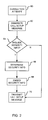
- FIG. 2 a flowchart of a method by which the originating MSS 18 inserts embedded security information into a setup message according to one embodiment of the invention is shown.
- the method is triggered by a Layer-3 SPVC connection attempt through the originating MSS 18 at step 60.
- the call control within the originating MSS 18 generates a call setup message for establishing a Layer-3 SPVC to the terminating MSS 24.
- the call control determines at step 64 whether security information is to be embedded in the call setup message. This determination may be made in any of a number of ways, depending on configuration.
- the call control may determine that all Layer-3 SPVC connections originating through a particular Layer-3 interface are to contain security information. Alternatively, the call control may determine that connections originating from one of a configured set of IP addresses are to contain security information. Generally, any test can be used to determine whether security information is to be embedded in the call setup message.
- the call control determines the security information to be embedded.
- the security information to be embedded can be determined in any of a number of ways, as long as the terminating MSS 24 will be able to know what embedded security information it should be looking for.
- the security information to be embedded must therefore be associated with the connection at some level. As an example, any connection between one of a configured set of originating users and one of a configured set of destination users can be associated with particular security information.
- associations between security information and a connection are: configured originating users on the originating MSS 18 attempting to access the terminating MSS 24; any connection between specified Layer-3 endpoints at the originating MSS 18 and specified Layer-3 endpoints at the terminating MSS 24; any connection originating at the originating MSS 18 and attempting to connect to configured destination users on the terminating MSS 24; specific services on the originating MSS 18 (such as video distribution, gaming, internet access); specific services being accessed on the terminating MSS 24; and connection within a CUG and/ or correct security information.
- the call control embeds the security information within the call setup message at step 68.
- the call control also sets a flag within the call setup message to indicate that the call setup message includes embedded security information (see below with reference to step 86 of FIG. 3).
- the call control transmits the call setup message to the terminating MSS 24.
- the call control also transmits the call setup message to the terminating MSS 24 if it was determined at step 64 that no security information was to be embedded in the call setup message.
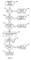
- FIG. 3 a flowchart of a method by which the terminating MSS 24 processes setup messages received from the originating MSS 18 during establishment of an SPVC according to one embodiment of the invention is shown.
- the call controller within the terminating MSS 24 receives a setup message from the originating MSS 18.
- the call controller determines whether the setup message corresponds to a Layer-3 connection by examining information elements within the setup message. If the setup message does not correspond to a Layer-3 connection, then at step 84 the call controller establishes a Layer-2 connection using conventional means.
- the call controller determines whether it is expecting security information to be embedded in the setup message. The call controller determines this in the same way as the call control within the originating MSS 18 determines whether security information is to be embedded in the call setup message, as described above with reference to step 64 of FIG. 2. Alternatively, if the call control of the originating MSS 18 sets a flag within the call setup message to indicate that the call setup message includes embedded security information, then the call controller within the terminating MSS 24 need simply determine the value of the flag. If the call controller determines that it is not expecting any embedded security information, then the call controller accepts the connection at step 88 by allocating a connection for the Layer-3 SPVC and sending a connect message to the originating MSS 18.
- the call controller determines at step 86 that it is expecting embedded security information, then at step 90 the call controller attempts to extract embedded security information, such as a CUG IC, from within the setup message. If there is no security information within the setup message, then the call controller rejects the connection at step 92. If call controller is able to extract embedded security information from the setup message, then at step 96 the call controller determines which anticipated security information relates to the setup message and retrieves the anticipated security information. The call controller determines which anticipated security information to expect based on the call scenario, using the same associations between call scenario and security information as is used by the call control within the originating MSS 18, described above with reference to step 66 of FIG. 2. For example, the call controller can determine the anticipated security information from membership of the calling user and the destination user in configured sets of users.
- embedded security information such as a CUG IC
- the call controller sends the embedded security information and the anticipated security information to the comparator.
- the comparator compares the two sets of security information, and returns a comparison result to the call controller. If at step 100 the comparison result indicates that the embedded security information corresponds to the anticipated security information, the call controller accepts the connection at step 102 by allocating a connection for the Layer-3 SPVC and sending a connect message to the originating MSS 18. Otherwise, the call controller rejects the connection at step 104.
- FIG. 4 a flowchart of a method by which the originating MSS 18 inserts embedded security information into a setup message according to another embodiment of the invention is shown.
- the method is triggered by a Layer-3 SVC attempt through the originating MSS 18 at step 110.
- the call control within the originating MSS 18 generates a call setup message for establishing a Layer-3 SVC to the terminating MSS 24.
- the call control determines at step 114 whether security information is to be embedded in the call setup message. This determination may be made in any of a number of ways, depending on configuration.
- the call control may determine that connections originating from one of a configured set of IP addresses are to contain security information. Alternatively, the call control may also determine that only connections that will terminate at one of a configured set of IP addresses are to contain security information. Generally, any test can be used to determine whether security information is to be embedded in the call setup message.
- the call control determines that security information is to be embedded in the call setup message. If the call control determines that security information is to be embedded in the call setup message, then at step 115 the call control determines the security information to be embedded. As an example, any connection between one of a configured set of originating users and one of a configured set of destination users can be associated with particular security information.
- associations between security information and a connection are: configured originating users on the originating MSS 18 attempting to access the terminating MSS 24; any connection originating at the originating MSS 18 and attempting to connect to configured destination users on the terminating MSS 24; any connection established through one of a set of configured IP interface addresses at the originating MSS; any connection established through one of a set of configured IP interface addresses at the terminating MSS; specific services on the originating MSS 18 (such as video distribution, gaming, internet access); specific services being accessed on the terminating MSS 24; and connection within a CUG.
- the security information to be embedded can be determined in any of a number of ways, as described above with reference to step 66 of FIG. 2, as long as the terminating MSS 24 will be able to know what embedded security information it should be looking for.
- the call control embeds the security information within the call setup message at step 116.
- the call control also sets a flag within the call setup message to indicate that the call setup message includes embedded security information.
- the call control transmits the call setup message to the terminating MSS 24.
- the call control also transmits the call setup message to the terminating MSS 24 if it was determined at step 114 that no security information was to be embedded in the call setup message.
- a flowchart of a method by which the terminating MSS 24 processes setup messages received from the originating MSS 18 during establishment of a Layer-3 SVC according to one embodiment of the invention is shown.
- the call controller within the terminating MSS 24 receives a setup message from the originating MSS 18.
- the call controller determines whether the setup message corresponds to a Layer-3 connection by examining information elements within the setup message. If the setup message does not correspond to a Layer-3 connection, then at step 124 the call controller establishes a Layer-2 connection using conventional means.
- the call controller determines whether it is expecting security information to be embedded in the setup message. The call controller determines this in the same way as the call control within the originating MSS 18 determines whether security information is to be embedded in the call setup message, as described above with reference to step 114 of FIG. 4. Alternatively, if the call control of the originating MSS 18 sets a flag within the call setup message to indicate that the call setup message includes embedded security information, then the call controller within the terminating MSS 24 need simply determine the value of the flag. If the call controller determines that it is not expecting any embedded security information, then the call controller accepts the connection at step 128 by allocating a connection for the Layer-3 SVC and sending a connect message to the originating MSS 18.
- the call controller determines at step 126 that it is expecting embedded security information, then at step 130 the call controller attempts to extract embedded security information, such as a CUG IC, from within the setup message. If there is no security information within the setup message, then the call controller rejects the connection at step 132. If the call controller is able to extract embedded security information, then at step 136 the call controller determines which anticipated security information relates to the setup message, and retrieves the anticipated security information. The call controller determines which anticipated security information to expect based on the call scenario, using the same associations between call scenario and security information as is used by the call control within the originating MSS 18, described above with reference to step 115 of FIG. 4. For example, the call controller can determine the anticipated security information from membership of the calling user and the destination user in configured sets of users.
- embedded security information such as a CUG IC
- the call controller sends the embedded security information and the anticipated security information to the comparator.
- the comparator compares the two sets of security information, and returns a comparison result to the call controller. If at step 140 the comparison result indicates that the embedded security information corresponds to the anticipated security information, the call controller accepts the connection at step 142 by allocating a connection and an IP interface to the SVC and sending a connect message to the originating MSS 18. Otherwise, the call controller rejects the connection at step 144.
- the methods described above with reference to FIG. 3 and FIG. 5 are combined into a single method, executed by a single set of instructions.
- the call controller determines whether the setup message is requesting a Layer-3 SPVC or a Layer-3 SVC. If the setup message is requesting a Layer-3 SPVC, then the call controller carries out the method described above with reference to steps 80 to 104 of FIG. 3. If the setup message is requesting a Layer-3 SVC, then the call controller carries out the method described above with reference to steps 120 to 144 of FIG. 5.
- the methods described above with reference to FIG. 2 and FIG. 4 can be combined in a similar manner.
- the invention has been described using Closed User Group Interlock Codes as an example of the security information used to verify whether a Layer-3 connection can be established.
- Other forms of security information can be used, as long as a correlation between the security information and the desired connection can be stored as anticipated security information.
- public/ private key protection schemes or encryption/ decryption keys may be used.
Landscapes
- Engineering & Computer Science (AREA)
- Computer Networks & Wireless Communication (AREA)
- Signal Processing (AREA)
- Computer Security & Cryptography (AREA)
- Computer Hardware Design (AREA)
- Computing Systems (AREA)
- General Engineering & Computer Science (AREA)
- Data Exchanges In Wide-Area Networks (AREA)
Abstract
Description
Claims (13)
- A method of establishing a secure Layer-3 connection across an ATM network, the Layer-3 connection having a first endpoint at an egress port of an originating multiservice switch (MSS) and a second endpoint at an ingress port of a terminating MSS, the method comprising the steps of:configuring the terminating MSS with anticipated security information;at the originating MSS, generating a setup message including embedded security information;sending the setup message to the terminating MSS;at the terminating MSS, extracting the embedded security information from the setup message;determining whether the embedded security information matches the anticipated security information; andif the embedded security information matches the anticipated security information, establishing the Layer-3 connection.
- The method of claim 1 wherein the Layer-3 connection is a Soft Permanent Virtual Circuit, and wherein the embedded security information and the anticipated security information are associated with the first endpoint.
- The method of claim 1 wherein the Layer-3 connection is a Soft Permanent Virtual Circuit, and wherein the embedded security information and the anticipated security information are associated with the second endpoint.
- The method of claim 1 wherein the embedded security information and the anticipated security information are Closed User Group Interlock Codes.
- The method of claim 1 wherein the Layer-3 connection is established by an originating user belonging to a configured set of originating users, and wherein the embedded security information and the anticipated security information are associated with the configured set of originating users.
- The method of claim 1 wherein the Layer-3 connection is established through an Internet Protocol (IP) interface address at the originating MSS belonging to a set of configured IP interface addresses, and wherein the embedded security information and the anticipated security information are associated with the configured set of IP interface addresses.
- The method of claim 1 wherein the Layer-3 connection is established to a terminating user belonging to a configured set of terminating users, and wherein the embedded security information and the anticipated security information are associated with the configured set of terminating users.
- The method of claim 1 wherein the Layer-3 connection is established through an Internet Protocol (IP) interface address at the terminating MSS belonging to a set of configured IP interface addresses, and wherein the embedded security information and the anticipated security information are associated with the configured set of IP interface addresses.
- The method of claim 1 comprising the further steps of:at the originating MSS, setting a value of a flag in the setup message to indicate that the setup message includes embedded security information;at the terminating MSS, reading the value of the flag before extracting the embedded security information.
- An originating multiservice switch (MSS) for establishing a secure Layer-3 connection across an ATM network to a terminating MSS, comprising a call control for generating a Layer-3 connection setup message including embedded security information, and for sending the setup message to the terminating MSS.
- A computer-readable medium comprising:instructions for generating a Layer-3 connection setup message to be sent from an originating multiservice switch (MSS) to a terminating MSS; andinstructions for embedding security information within the setup message.
- A terminating multiservice switch (MSS) for establishing a secure Layer-3 connection across an ATM network from an originating MSS, comprising:stored anticipated security information;means for querying a comparator of two pieces of security information; anda call controller for receiving a Layer-3 connection setup message, for extracting embedded security information from the setup message, for querying the comparator to determine whether the embedded security information corresponds to the anticipated security information, and for establishing the Layer-3 connection in the event that the embedded security information corresponds to the anticipated security information.
- A computer-readable medium comprising:instructions for receiving a Layer-3 connection setup message received from an originating multiservice switch;instructions for extracting embedded security information from the setup message;instructions for retrieving anticipated security information;instructions for determining whether the embedded security information corresponds to the anticipated security information; andinstructions for establishing a Layer-3 connection in the event that the embedded security information corresponds to the anticipated security information.
Applications Claiming Priority (2)
| Application Number | Priority Date | Filing Date | Title |
|---|---|---|---|
| US814330 | 1985-12-30 | ||
| US10/814,330 US7978707B2 (en) | 2004-04-01 | 2004-04-01 | Method and apparatus for securely establishing L3-SVC connections |
Publications (2)
| Publication Number | Publication Date |
|---|---|
| EP1598999A2 true EP1598999A2 (en) | 2005-11-23 |
| EP1598999A3 EP1598999A3 (en) | 2005-12-28 |
Family
ID=34980155
Family Applications (1)
| Application Number | Title | Priority Date | Filing Date |
|---|---|---|---|
| EP05300236A Withdrawn EP1598999A3 (en) | 2004-04-01 | 2005-03-31 | Method and apparatus for securely establishing L3-SVC connections |
Country Status (2)
| Country | Link |
|---|---|
| US (3) | US7978707B2 (en) |
| EP (1) | EP1598999A3 (en) |
Cited By (1)
| Publication number | Priority date | Publication date | Assignee | Title |
|---|---|---|---|---|
| US4946269A (en) * | 1987-06-23 | 1990-08-07 | Med Optics Corporation | Colored contact lens |
Families Citing this family (3)
| Publication number | Priority date | Publication date | Assignee | Title |
|---|---|---|---|---|
| US7978707B2 (en) * | 2004-04-01 | 2011-07-12 | Alcatel Lucent | Method and apparatus for securely establishing L3-SVC connections |
| US9787607B2 (en) * | 2011-04-04 | 2017-10-10 | Infinera Corporation | End-to-end provisioning of Ethernet Virtual Circuits |
| US9155120B2 (en) * | 2013-09-13 | 2015-10-06 | Nvidia Corporation | Call establishment |
Family Cites Families (16)
| Publication number | Priority date | Publication date | Assignee | Title |
|---|---|---|---|---|
| SE508844C2 (en) * | 1997-02-19 | 1998-11-09 | Postgirot Bank Ab | Procedure for access control with SIM card |
| US5987520A (en) * | 1997-09-18 | 1999-11-16 | Ascend Communications, Inc. | Closed user group preprocessing decision for efficient call security validation |
| US7227837B1 (en) * | 1998-04-30 | 2007-06-05 | At&T Labs, Inc. | Fault tolerant virtual tandem switch |
| US6829242B2 (en) * | 1998-06-30 | 2004-12-07 | Cisco Technology, Inc. | Method and apparatus for associating PVC identifiers with domain names of home gateways |
| AU2001231039A1 (en) * | 2000-01-20 | 2001-07-31 | Mci Worldcom, Inc. | Intelligent network and method for providing voice telephony over atm and alias addressing |
| US20020003776A1 (en) * | 2000-04-28 | 2002-01-10 | Gokhale Dilip S. | Interworking unit for integrating terrestrial ATM switches with broadband satellite networks |
| US6748471B1 (en) * | 2000-10-16 | 2004-06-08 | Electronics For Imaging, Inc. | Methods and apparatus for requesting and receiving a print job via a printer polling device associated with a printer |
| AU2002214691A1 (en) | 2000-11-06 | 2002-05-15 | Sbc Technology Resources, Inc. | Secure atm-based distributed virtual tandem switching system and method |
| JP3546954B2 (en) * | 2000-11-27 | 2004-07-28 | 日本電気株式会社 | Routing S-PVC setting system in PNNI-operated ATM exchange network |
| US7224801B2 (en) * | 2000-12-27 | 2007-05-29 | Logitech Europe S.A. | Wireless secure device |
| WO2002076027A1 (en) | 2001-03-21 | 2002-09-26 | Corecess Inc. | Adsl access multiplexer connected to ethernet and adsl network system using the same |
| US7187678B2 (en) * | 2001-08-13 | 2007-03-06 | At&T Labs, Inc. | Authentication for use of high speed network resources |
| US7701953B2 (en) * | 2002-11-04 | 2010-04-20 | At&T Intellectual Property I, L.P. | Client server SVC-based DSL service |
| US7602788B2 (en) * | 2002-11-04 | 2009-10-13 | At&T Intellectual Property I, L.P. | Peer to peer SVC-based DSL service |
| US8046463B1 (en) * | 2003-08-27 | 2011-10-25 | Cisco Technology, Inc. | Method and apparatus for controlling double-ended soft permanent virtual circuit/path connections |
| US7978707B2 (en) * | 2004-04-01 | 2011-07-12 | Alcatel Lucent | Method and apparatus for securely establishing L3-SVC connections |
-
2004
- 2004-04-01 US US10/814,330 patent/US7978707B2/en not_active Expired - Fee Related
-
2005
- 2005-03-31 EP EP05300236A patent/EP1598999A3/en not_active Withdrawn
-
2011
- 2011-05-24 US US13/114,682 patent/US8837489B2/en not_active Expired - Fee Related
-
2014
- 2014-09-12 US US14/484,926 patent/US20150046694A1/en not_active Abandoned
Cited By (1)
| Publication number | Priority date | Publication date | Assignee | Title |
|---|---|---|---|---|
| US4946269A (en) * | 1987-06-23 | 1990-08-07 | Med Optics Corporation | Colored contact lens |
Also Published As
| Publication number | Publication date |
|---|---|
| US20150046694A1 (en) | 2015-02-12 |
| US8837489B2 (en) | 2014-09-16 |
| EP1598999A3 (en) | 2005-12-28 |
| US20050220119A1 (en) | 2005-10-06 |
| US20110222546A1 (en) | 2011-09-15 |
| US7978707B2 (en) | 2011-07-12 |
Similar Documents
| Publication | Publication Date | Title |
|---|---|---|
| US8483225B2 (en) | Intelligent policy server system and method for bandwidth control in an ATM network | |
| US7382785B2 (en) | Extended virtual user-to-network interface with ATM network | |
| US7263557B2 (en) | Method and apparatus to detect configuration information for a digital subscriber line device | |
| US8199760B2 (en) | Peer to peer SVC-based DSL service | |
| US7864773B2 (en) | Virtual circuit auto-configuration for customer premises equipment | |
| US20090003341A1 (en) | Controlled transmissions across packet networks | |
| US6785228B1 (en) | Subscriber permissions and restrictions for switched connections in a communications network | |
| CN101047618B (en) | Method and system for acquiring network route information | |
| US6353856B1 (en) | Firewall system and method | |
| US6990110B2 (en) | Automatic permanent virtual circuit connection activation for connection oriented networks | |
| US5999524A (en) | Dial access switching interface for frame relay | |
| US20150046694A1 (en) | Method and apparatus for securely establishing l3-svc connections | |
| US6661795B1 (en) | Method and apparatus for efficient signaling in an ATM environment | |
| EP1404081A1 (en) | Method for establishing a connection between subscribers and service providers granted by an authentication server | |
| JP2001036561A (en) | TCP / IP network system | |
| US7046675B2 (en) | Method and apparatus to configure a digital subscriber line device | |
| US7289488B2 (en) | Method for automatically configuring a DSLAM to recognize customer premises equipment | |
| US6917619B1 (en) | System and method for interconnecting ATM systems over an intermediate ATM network using switch virtual connections | |
| KR100462896B1 (en) | Dsl access multiplexor and network system using it | |
| Venieris et al. | DQDB MAN as a Transit Network for ATM CPNs | |
| Laurent | Security flows analysis of the atm emulated lan architecture | |
| JPH1188336A (en) | Communication management method and device | |
| Guide | APX 8000™/MAX TNT®/DSLTNT™ | |
| US20060072601A1 (en) | Virtual IP interface | |
| Shankaran | Asynchronous transfer mode security |
Legal Events
| Date | Code | Title | Description |
|---|---|---|---|
| PUAI | Public reference made under article 153(3) epc to a published international application that has entered the european phase |
Free format text: ORIGINAL CODE: 0009012 |
|
| PUAL | Search report despatched |
Free format text: ORIGINAL CODE: 0009013 |
|
| AK | Designated contracting states |
Kind code of ref document: A2 Designated state(s): AT BE BG CH CY CZ DE DK EE ES FI FR GB GR HU IE IS IT LI LT LU MC NL PL PT RO SE SI SK TR |
|
| AX | Request for extension of the european patent |
Extension state: AL BA HR LV MK YU |
|
| AK | Designated contracting states |
Kind code of ref document: A3 Designated state(s): AT BE BG CH CY CZ DE DK EE ES FI FR GB GR HU IE IS IT LI LT LU MC NL PL PT RO SE SI SK TR |
|
| AX | Request for extension of the european patent |
Extension state: AL BA HR LV MK YU |
|
| RIC1 | Information provided on ipc code assigned before grant |
Ipc: 7H 04L 29/06 B Ipc: 7H 04L 12/56 A |
|
| 17P | Request for examination filed |
Effective date: 20060628 |
|
| 17Q | First examination report despatched |
Effective date: 20060720 |
|
| AKX | Designation fees paid |
Designated state(s): AT BE BG CH CY CZ DE DK EE ES FI FR GB GR HU IE IS IT LI LT LU MC NL PL PT RO SE SI SK TR |
|
| RAP1 | Party data changed (applicant data changed or rights of an application transferred) |
Owner name: ALCATEL LUCENT |
|
| 17Q | First examination report despatched |
Effective date: 20060720 |
|
| STAA | Information on the status of an ep patent application or granted ep patent |
Free format text: STATUS: THE APPLICATION IS DEEMED TO BE WITHDRAWN |
|
| 18D | Application deemed to be withdrawn |
Effective date: 20071016 |