EP1598963A1 - Multi-wavelength CD and PMD compensator - Google Patents
Multi-wavelength CD and PMD compensator Download PDFInfo
- Publication number
- EP1598963A1 EP1598963A1 EP04292626A EP04292626A EP1598963A1 EP 1598963 A1 EP1598963 A1 EP 1598963A1 EP 04292626 A EP04292626 A EP 04292626A EP 04292626 A EP04292626 A EP 04292626A EP 1598963 A1 EP1598963 A1 EP 1598963A1
- Authority
- EP
- European Patent Office
- Prior art keywords
- dispersion
- polarization
- optical
- parallel
- different wavelength
- Prior art date
- Legal status (The legal status is an assumption and is not a legal conclusion. Google has not performed a legal analysis and makes no representation as to the accuracy of the status listed.)
- Granted
Links
- 239000006185 dispersion Substances 0.000 claims abstract description 74
- 230000010287 polarization Effects 0.000 claims abstract description 71
- 230000003287 optical effect Effects 0.000 claims abstract description 70
- 238000000034 method Methods 0.000 claims abstract description 22
- 230000005540 biological transmission Effects 0.000 claims abstract description 17
- 238000013213 extrapolation Methods 0.000 claims abstract 2
- 238000004590 computer program Methods 0.000 claims description 9
- 230000003595 spectral effect Effects 0.000 claims description 3
- 238000001228 spectrum Methods 0.000 description 13
- 230000006978 adaptation Effects 0.000 description 11
- 239000000835 fiber Substances 0.000 description 10
- 238000012545 processing Methods 0.000 description 8
- 238000004422 calculation algorithm Methods 0.000 description 6
- 239000013307 optical fiber Substances 0.000 description 5
- 238000010586 diagram Methods 0.000 description 4
- 239000011159 matrix material Substances 0.000 description 4
- 238000005259 measurement Methods 0.000 description 4
- 238000012546 transfer Methods 0.000 description 4
- 230000000694 effects Effects 0.000 description 2
- 230000000116 mitigating effect Effects 0.000 description 2
- VYZAMTAEIAYCRO-UHFFFAOYSA-N Chromium Chemical compound [Cr] VYZAMTAEIAYCRO-UHFFFAOYSA-N 0.000 description 1
- 230000018199 S phase Effects 0.000 description 1
- 238000013459 approach Methods 0.000 description 1
- 230000008901 benefit Effects 0.000 description 1
- 238000004364 calculation method Methods 0.000 description 1
- 230000015556 catabolic process Effects 0.000 description 1
- 230000008859 change Effects 0.000 description 1
- 238000005253 cladding Methods 0.000 description 1
- 238000004891 communication Methods 0.000 description 1
- 238000012937 correction Methods 0.000 description 1
- 239000013078 crystal Substances 0.000 description 1
- 230000007423 decrease Effects 0.000 description 1
- 238000006731 degradation reaction Methods 0.000 description 1
- 230000001934 delay Effects 0.000 description 1
- 230000001419 dependent effect Effects 0.000 description 1
- 238000001514 detection method Methods 0.000 description 1
- 238000011161 development Methods 0.000 description 1
- 230000018109 developmental process Effects 0.000 description 1
- 238000005516 engineering process Methods 0.000 description 1
- 238000002474 experimental method Methods 0.000 description 1
- 230000007274 generation of a signal involved in cell-cell signaling Effects 0.000 description 1
- 230000006872 improvement Effects 0.000 description 1
- 238000012804 iterative process Methods 0.000 description 1
- 239000004973 liquid crystal related substance Substances 0.000 description 1
- 239000000203 mixture Substances 0.000 description 1
- 230000003094 perturbing effect Effects 0.000 description 1
- 238000004088 simulation Methods 0.000 description 1
- 230000007480 spreading Effects 0.000 description 1
Images


Classifications
-
- H—ELECTRICITY
- H04—ELECTRIC COMMUNICATION TECHNIQUE
- H04B—TRANSMISSION
- H04B10/00—Transmission systems employing electromagnetic waves other than radio-waves, e.g. infrared, visible or ultraviolet light, or employing corpuscular radiation, e.g. quantum communication
- H04B10/25—Arrangements specific to fibre transmission
- H04B10/2507—Arrangements specific to fibre transmission for the reduction or elimination of distortion or dispersion
- H04B10/2572—Arrangements specific to fibre transmission for the reduction or elimination of distortion or dispersion due to forms of polarisation-dependent distortion other than PMD
-
- H—ELECTRICITY
- H04—ELECTRIC COMMUNICATION TECHNIQUE
- H04B—TRANSMISSION
- H04B10/00—Transmission systems employing electromagnetic waves other than radio-waves, e.g. infrared, visible or ultraviolet light, or employing corpuscular radiation, e.g. quantum communication
- H04B10/25—Arrangements specific to fibre transmission
- H04B10/2507—Arrangements specific to fibre transmission for the reduction or elimination of distortion or dispersion
- H04B10/2513—Arrangements specific to fibre transmission for the reduction or elimination of distortion or dispersion due to chromatic dispersion
Definitions
- the present invention relates to a method for performing optical dispersion compensation of wavelength division multiplexed WDM optical signals providing a compensation stage with an optical transmission medium to be used as parallel operating cascade of polarization controllers and optical birefringent elements to compensate dispersion of WDM optical signals when being transmitted spectrally dispersed into the different wavelengths channels in parallel through the polarization controller. Furthermore, it is related to a computer readable medium having a computer program recorded thereon, the computer program comprising codes adapted to perform a procedure when said computer program is run on a control unit for an optical transmission medium to be used as polarization controllers to compensate dispersion of wavelength division multiplexed WDM optical signals.
- the input data stream of an optical transmission system may be viewed as a series of light pulses representing digital bits.
- the bit rate of current optical transmission systems generally range from 10 Gbit/s to 40 Gbit/s resulting in light pulses (or bit periods) that are, respectively, 100 to 25 picoseconds (psecs) wide.
- Receivers in an optical transmission system convert each bit period in the data stream into digital ones or zeros by determining, for each bit period, whether a light pulse has been received (digital one) or not (digital zero).
- Polarization mode dispersion is a phenomenon that may distort the light pulses of the data stream and thus impair the ability of a receiver to determine whether a bit period should be converted into a one or zero.
- PMD limits the transmission accuracy and capacity of optical transmission systems and therefore is a critical parameter in optical communications.
- the fundamental mode of a single mode optical fiber is the solution to the wave equation that satisfies the boundary conditions at the core-cladding interface. Although this appears to be counter-intuitive, there are two solutions to the wave equation that correspond to the fundamental mode. The fiber is deemed to be a single mode fiber because both solutions have the same propagation constant. The two solutions are referred to as the polarization modes. These polarization components are mutually orthogonal.
- the state of polarization refers to the distribution of light energy between the two polarization modes.
- the two polarization modes have slightly different propagation constants that give rise to pulse spreading.
- One polarization mode is referred to as the "fast-mode”
- the other polarization mode is known as the "slow-mode”.
- the fast mode and the slow mode mix as they travel down the fiber, becoming indistinguishable.
- the resulting difference in propagation time between polarization modes is known as the differential group delay.
- Optical signal transmitted through an optical fiber are subjected also to another physical dispersion known as chromatic dispersion (CD).
- CD chromatic dispersion
- each wavelength of the optical signals travels through a given medium, such as an optical fiber, at a different speed. Since the various wavelengths of light have different velocities, a given wavelength of light will arrive at a receiver disposed at the end of a transmission fiber before another wavelength of light will arrive at that receiver. The time delay between different wavelengths of light leads to pulse broadening.
- Chromatic dispersion is obtained in an optical fiber by measuring fiber group delays in the time domain. Chromatic dispersion is a relatively stable phenomenon. It can be in the range of 300-500psec in a 10Gb/s system before incurring a 1dB power penalty. In a 40Gb/s system, the range decreases to 18-25psec.
- CD can be time variant as a result of changes with temperature or stress, but typically, the time variance of CD is not particularly strong.
- PMD is very time variant, and thus, compensation should track with time. PMD describes the statistical broadening of optical pulses within an optical fiber caused by polarization effects. This broadening effect, similar to pulse broadening from chromatic dispersion, ultimately prevents the correct detection of the waveform at the receiver.
- WO 03/040777 is described an integrated system for performing dispersion compensation on wavelength channels in WDM or DWDM transmissions (D for dense).
- the system includes a tunable integrated dispersion compensation module that performs chromatic dispersion compensation and polarization mode dispersion compensation on each of the wavelength channels in the transmission. Feedback is used to adjust the tunable integrated dispersion compensation module until receiver performance is optimized.
- Such an integrated system as described in WO 03/040777 has the big disadvantage to require a specific dispersion compensation module for each different wavelength channels of the optical signals. A dispersion compensation using such solution will imply high costs and therefore can not be really efficient.
- WO 02/080411 a method and apparatus for compensation for polarization mode dispersion (PMD) in an optical transmission system without perturbing the laser source.
- PMD polarization mode dispersion
- Such optical PMD compensator is rather attractive for bit rates from 10GHz to 40GHz WDM optical transmission system.
- the approach is cost-effective due to parallel processing of many channels within one hardware (Liquid crystal display array for polarization controllers) and one birefringent crystal (polarization maintaining fiber) for all parallel wavelength channels.
- only one wavelength scanning polarimeter (feedback signal) is shared among all channels.
- fastfeed-forward adaptation which avoids time consuming dither techniques i.e. consecutive variations of polarization controller tuning parameters into the direction of an optimized feedback signal.
- the method comprise the steps of providing a compensation stage with an optical transmission medium to be used as parallel operating cascade of polarization controllers and optical birefringent elements to compensate dispersion of the WDM optical signals when being transmitted spectrally dispersed into the different wavelength channels in parallel through the parallel cascades.
- the polarization states of the different wavelength components of each channel (polarization spectrum of each channel) of the whole optical signals has to be determined to define accordingly a signal for each channel (here referred to as PMD feedback signal) required for time efficient setting of the polarization controllers in one step when compensating in parallel the polarization mode dispersion at each different wavelength channel by parallel arranged polarization controller and birefringent element cascades.
- the method is characterized by the further steps of determining the chromatic dispersion of the optical signals at one or few different wavelength channels in addition. Such measurement of the chromatic dispersion can be used possibly to extrapolate the chromatic dispersion occurring at the other wavelength channels.
- a feedback signal (here referred to as feedback signal 2 or CD feedback signal) has to be defined accordingly as required when compensating in parallel the chromatic dispersion at each different wavelength channel.
- the polarization controller setting per wavelength channel is calculated using feedback signals from both polarization mode dispersion (PMD feedback signal) and chromatic dispersion (CD feedback signal). And finally, the respective setting are applied in parallel on the polarization controllers to compensate optical dispersion of the WDM optical signals at each different wavelength channel.
- a computer readable medium having a computer program recorded thereon, the computer program comprising codes adapted to perform a procedure when said computer program is run on a control unit for an optical transmission medium to be used as polarization controllers to compensate dispersion of wavelength division multiplexed WDM optical signals.
- Such procedure corresponds to an adaptation algorithm performing a step of collecting feedback signal (PMD feedback signal) required for the polarization controllers setting when compensating in parallel the polarization mode dispersion at each different wavelength channel of the WDM optical signals when being transmitted spectrally dispersed into the different wavelength channels through the polarization controller.
- PMD feedback signal feedback signal
- That procedure is characterized by collecting feedback signal (CD feedback signal) required when compensating in parallel the chromatic dispersion at each different wavelength channel. Then, the polarization controller setting per wavelength channel is calculated using feedback signals from both polarization mode dispersion and chromatic dispersion. Finally, the control unit provides in parallel the respective setting on the polarization controllers to compensate optical dispersion of the WDM optical signals at each different wavelength channel.
- CD feedback signal feedback signal
- the polarization controller setting per wavelength channel is calculated using feedback signals from both polarization mode dispersion and chromatic dispersion.
- the structure of a multi-channel dispersion compensator is shown on figure 1. It is similar to a multi-channel PMD compensator except the at least one further feedback signal sensitive for CD variation (FB, FB1, FB2,%) for the new control algorithm which work even in the absence of PMD determining the optimum compensation for chromatic dispersion.
- Such control algorithm is adapted to determine the optimum setting mitigating both distortions coming from CD and PMD.
- the structure works as follows: A wavelength demux distributes each channel at an individual cascade of polarization controller PC and birefringent element polarization maintaining fiber (PMF). A cascade of two is shown, but more would be conceivable. At the output, the signals of all parallel operating cascades are concentrated again in one fiber by a wavelength mux.
- a spectral polarimeter determines the polarization spectrum of each channel; this could be performed by a scanning optical filter followed by a polarimeter. From the extracted polarization information (e.g. polarization describing Stokes vector S vs. optical frequency ⁇ , the optimum setting of the PCs to minimize the distortion (leading to a penalty) is calculated and commanded to the PCs.
- polarization information e.g. polarization describing Stokes vector S vs. optical frequency ⁇
- a feedback signal for the CD mitigation is added according to the invention.
- Two alternatives of positioning the feedback signal generation unit are sketched out in Fig. 1. Additional alternatives are shown in Fig. 2:
- the adaptation algorithm is implemented in the control unit for a simultaneous PMD and CD compensation depending on the feedback signal. Nevertheless, parallel to the CD adaptation and compensation based on the observation of the CD relevant feedback signals, the PMD compensation is applied by the feed-forward adaptation scheme. In general PMD compensation operates on a different time scale (faster).
- the CD adaptations differs fort the different feedback signals FB:
- the states of polarization SOP at different spectral positions can be described by the real 3-dimensional Stokes vector S( ⁇ ) or by the complex 2-dimensional Jones vector a(m).
- the output SOP (state-of-polarization) is measured by a wavelength scanning polarimeter.
- a state-of-the-art realization is shown in fig.4.
- a tunable narrowband optical filter selects a subband of the optical signal spectrum.
- the wavelength is commanded by the adaptation control.
- the output is launched into a standard polarimeter setup which determines the relative optical power of differently polarized components of the signal, selected by polarizers with different polarization pass axes by photo diodes.
- I1., I2 and I3 are the photo currents for linear 0 degree, linear 45 degree, and left hand circular polarized components. 10 is the total power of the signal.
- the Stokes vector (point on the Poincaré sphere) is given by
- FIG.4 An alternative realization of the wavelength scanning polarimeter is shown in fig.4, where two polarimeters are operating in parallel.
- the signal launched into the lower one is pre-processed by an optical birefringent element.
- This element could improve the chromatic dispersion compensation at positions, where the optical signal processing in fig.1 or 2, the PC and PMF cascade, is not in a position to efficiently transfer the signal's phase distortion (due to chromatic dispersion) into a polarization variation within the signal spectrum.
- the known birefringence will serve as discriminating element.
- the PC setting can be calculated as follows:
- the input field (cf. fig.1 or 2) can be described by a Jones vector ⁇ in ( ⁇ ) , which is wavelength independent in the case of no PMD, a scalar amplitude spectrum b( ⁇ ) and a phase spectrum ⁇ ( ⁇ ).
- E in ( ⁇ ) a in ( ⁇ )e j ⁇ in( ⁇ ) ⁇ b( ⁇ ) ⁇ E 0
- W is decomposed into factors Fk and Mk . They describe the matrices of the birefringence PMFk and the polarization controller PCk, respectively.
- the setting parameters of the PC which are controlled by the adaptation control unit, are p k,i .
- PC with a different Jones matrix and different setting parameters pi are also possible.
- the choice is mainly determined by the technology.
- a cascade of differently oriented wave plates and tunable Faraday rotators might by suitable for an advantageous realization.
Landscapes
- Physics & Mathematics (AREA)
- Electromagnetism (AREA)
- Engineering & Computer Science (AREA)
- Computer Networks & Wireless Communication (AREA)
- Signal Processing (AREA)
- Optical Communication System (AREA)
Abstract
Description
- The present invention relates to a method for performing optical dispersion compensation of wavelength division multiplexed WDM optical signals providing a compensation stage with an optical transmission medium to be used as parallel operating cascade of polarization controllers and optical birefringent elements to compensate dispersion of WDM optical signals when being transmitted spectrally dispersed into the different wavelengths channels in parallel through the polarization controller. Furthermore, it is related to a computer readable medium having a computer program recorded thereon, the computer program comprising codes adapted to perform a procedure when said computer program is run on a control unit for an optical transmission medium to be used as polarization controllers to compensate dispersion of wavelength division multiplexed WDM optical signals.
- The input data stream of an optical transmission system may be viewed as a series of light pulses representing digital bits. The bit rate of current optical transmission systems generally range from 10 Gbit/s to 40 Gbit/s resulting in light pulses (or bit periods) that are, respectively, 100 to 25 picoseconds (psecs) wide. Receivers in an optical transmission system convert each bit period in the data stream into digital ones or zeros by determining, for each bit period, whether a light pulse has been received (digital one) or not (digital zero).
- Polarization mode dispersion (PMD) is a phenomenon that may distort the light pulses of the data stream and thus impair the ability of a receiver to determine whether a bit period should be converted into a one or zero. As a result, PMD limits the transmission accuracy and capacity of optical transmission systems and therefore is a critical parameter in optical communications. The fundamental mode of a single mode optical fiber is the solution to the wave equation that satisfies the boundary conditions at the core-cladding interface. Although this appears to be counter-intuitive, there are two solutions to the wave equation that correspond to the fundamental mode. The fiber is deemed to be a single mode fiber because both solutions have the same propagation constant. The two solutions are referred to as the polarization modes. These polarization components are mutually orthogonal. The state of polarization refers to the distribution of light energy between the two polarization modes. In practice, since the cross-sectional area of a fiber is not perfectly circular, the two polarization modes have slightly different propagation constants that give rise to pulse spreading. One polarization mode is referred to as the "fast-mode", and the other polarization mode is known as the "slow-mode". The fast mode and the slow mode mix as they travel down the fiber, becoming indistinguishable. The resulting difference in propagation time between polarization modes is known as the differential group delay.
- Optical signal transmitted through an optical fiber are subjected also to another physical dispersion known as chromatic dispersion (CD). This occurs because each wavelength of the optical signals travels through a given medium, such as an optical fiber, at a different speed. Since the various wavelengths of light have different velocities, a given wavelength of light will arrive at a receiver disposed at the end of a transmission fiber before another wavelength of light will arrive at that receiver. The time delay between different wavelengths of light leads to pulse broadening. Chromatic dispersion is obtained in an optical fiber by measuring fiber group delays in the time domain. Chromatic dispersion is a relatively stable phenomenon. It can be in the range of 300-500psec in a 10Gb/s system before incurring a 1dB power penalty. In a 40Gb/s system, the range decreases to 18-25psec.
- CD can be time variant as a result of changes with temperature or stress, but typically, the time variance of CD is not particularly strong. PMD, on the other hand, is very time variant, and thus, compensation should track with time. PMD describes the statistical broadening of optical pulses within an optical fiber caused by polarization effects. This broadening effect, similar to pulse broadening from chromatic dispersion, ultimately prevents the correct detection of the waveform at the receiver.
- In WO 03/040777 is described an integrated system for performing dispersion compensation on wavelength channels in WDM or DWDM transmissions (D for dense). The system includes a tunable integrated dispersion compensation module that performs chromatic dispersion compensation and polarization mode dispersion compensation on each of the wavelength channels in the transmission. Feedback is used to adjust the tunable integrated dispersion compensation module until receiver performance is optimized. Such an integrated system as described in WO 03/040777 has the big disadvantage to require a specific dispersion compensation module for each different wavelength channels of the optical signals. A dispersion compensation using such solution will imply high costs and therefore can not be really efficient.
- In WO 02/080411 is described a method and apparatus for compensation for polarization mode dispersion (PMD) in an optical transmission system without perturbing the laser source. Such optical PMD compensator is rather attractive for bit rates from 10GHz to 40GHz WDM optical transmission system. Indeed, the approach is cost-effective due to parallel processing of many channels within one hardware (Liquid crystal display array for polarization controllers) and one birefringent crystal (polarization maintaining fiber) for all parallel wavelength channels. Also only one wavelength scanning polarimeter (feedback signal) is shared among all channels. Furthermore, it is taken advantage of the use of fastfeed-forward adaptation which avoids time consuming dither techniques i.e. consecutive variations of polarization controller tuning parameters into the direction of an optimized feedback signal.
- Nevertheless, a solution as proposed in WO 02/080411 has still the big drawback that neither chromatic dispersion (CD) or transmitter shirp nor self-phase modulation (SPM) can be compensated.
- In view of the above, it is an object of the present invention to provide a method for perfuming optical dispersion compensation of wavelength division multiplexed optical signals based not only on polarization mode dispersion but also on chromatic dispersion in a cost effective way.
- This object is achieved in accordance with the invention by applying a method for performing optical dispersion compensation of wavelength division multiplexed (WDM) optical signals. The method comprise the steps of providing a compensation stage with an optical transmission medium to be used as parallel operating cascade of polarization controllers and optical birefringent elements to compensate dispersion of the WDM optical signals when being transmitted spectrally dispersed into the different wavelength channels in parallel through the parallel cascades. The polarization states of the different wavelength components of each channel (polarization spectrum of each channel) of the whole optical signals has to be determined to define accordingly a signal for each channel (here referred to as PMD feedback signal) required for time efficient setting of the polarization controllers in one step when compensating in parallel the polarization mode dispersion at each different wavelength channel by parallel arranged polarization controller and birefringent element cascades. The method is characterized by the further steps of determining the chromatic dispersion of the optical signals at one or few different wavelength channels in addition. Such measurement of the chromatic dispersion can be used possibly to extrapolate the chromatic dispersion occurring at the other wavelength channels. Then, a feedback signal (here referred to as feedback signal 2 or CD feedback signal) has to be defined accordingly as required when compensating in parallel the chromatic dispersion at each different wavelength channel. The polarization controller setting per wavelength channel is calculated using feedback signals from both polarization mode dispersion (PMD feedback signal) and chromatic dispersion (CD feedback signal). And finally, the respective setting are applied in parallel on the polarization controllers to compensate optical dispersion of the WDM optical signals at each different wavelength channel.
- In accordance with another aspect of the invention, its object is achieved by a computer readable medium having a computer program recorded thereon, the computer program comprising codes adapted to perform a procedure when said computer program is run on a control unit for an optical transmission medium to be used as polarization controllers to compensate dispersion of wavelength division multiplexed WDM optical signals. Such procedure corresponds to an adaptation algorithm performing a step of collecting feedback signal (PMD feedback signal) required for the polarization controllers setting when compensating in parallel the polarization mode dispersion at each different wavelength channel of the WDM optical signals when being transmitted spectrally dispersed into the different wavelength channels through the polarization controller. That procedure is characterized by collecting feedback signal (CD feedback signal) required when compensating in parallel the chromatic dispersion at each different wavelength channel. Then, the polarization controller setting per wavelength channel is calculated using feedback signals from both polarization mode dispersion and chromatic dispersion. Finally, the control unit provides in parallel the respective setting on the polarization controllers to compensate optical dispersion of the WDM optical signals at each different wavelength channel.
- Advantageous developments of the invention are described in the dependent claims, the following description and the drawings.
- An exemplary embodiment of the invention will now be explained further with the reference to the attached drawings in which:
- Fig. 1
- is a diagram of a compensation stage according to the invention;
- Fig. 2
- is a diagram of a similar compensation stage showing different possible origin for the used feedback signal;
- Fig. 3
- is a diagram of a wavelength scanning polarimeter;
- Fig. 4
- is a diagram of an alternative polarization of the wavelength scanning polarimeter
- The structure of a multi-channel dispersion compensator is shown on figure 1. It is similar to a multi-channel PMD compensator except the at least one further feedback signal sensitive for CD variation (FB, FB1, FB2,...) for the new control algorithm which work even in the absence of PMD determining the optimum compensation for chromatic dispersion. Such control algorithm is adapted to determine the optimum setting mitigating both distortions coming from CD and PMD. In detail, the structure works as follows: A wavelength demux distributes each channel at an individual cascade of polarization controller PC and birefringent element polarization maintaining fiber (PMF). A cascade of two is shown, but more would be conceivable. At the output, the signals of all parallel operating cascades are concentrated again in one fiber by a wavelength mux. At the output of the mux a spectral polarimeter determines the polarization spectrum of each channel; this could be performed by a scanning optical filter followed by a polarimeter. From the extracted polarization information (e.g. polarization describing Stokes vector S vs. optical frequency ω, the optimum setting of the PCs to minimize the distortion (leading to a penalty) is calculated and commanded to the PCs.
- Compared to the state-of-the-art, a feedback signal for the CD mitigation is added according to the invention. Two alternatives of positioning the feedback signal generation unit are sketched out in Fig. 1. Additional alternatives are shown in Fig. 2:
- At the common output of the signal processing unit an optical channel filter selects a channel, which generates the feedback signal FB (PMD feedback signal) for the adaptation control unit.
- The feedback signal FB2 (CD feedback signal) is extracted from a single channel path within the signal processing (see Fig. 1 and Fig. 2).
- Alternatively, a feedback signal can be extracted at the signal processing input, as for FB4 (CD feedback signal) shown in Fig. 2 or with an optical filter as FB1 (PMD feedback signal) in Fig. 2, but at the common input port.
- A feedback signal FB3 (see Fig. 2) from an external unit can also be applied. It is directly related to the forward error correction (FEC) error count which is extracted from the FEC circuit in a receiver for one channel.
- Two different kinds of feedback signal for the CD compensation can be applied:
- i. A scalar signal which has to be maximized (or minimized) such as eye monitor feedback (eye opening, Q-factor estimate); but also FEC error count, which has to be minimized, belongs to this group. These FB signals are sensitive to any signal degradation, hence also to a non-compensated PMD compensation. Therefore they can only be extracted from the output side of the compensator (FB1, FB2, FB3 of Fig.2).
- ii. A signal which is a direct measure of the chromatic dispersion. It is not applicable for all modulation formats. It splits upper and lower side-band from the optical channel, detects them separately in two receivers, and compares the clock phase difference between the two receivers. This difference is a direct measure for the CD. Since it is blind for PMD distortion, it can be extracted at both sides of the compensator, i.e. FB4 (then it measures the link CD) or also FB2 and FB3 (then it measures the link + actually set compensator CD).
-
- The adaptation algorithm is implemented in the control unit for a simultaneous PMD and CD compensation depending on the feedback signal. Nevertheless, parallel to the CD adaptation and compensation based on the observation of the CD relevant feedback signals, the PMD compensation is applied by the feed-forward adaptation scheme. In general PMD compensation operates on a different time scale (faster).
- With help of the wavelength scanning polarimeter measurement of each channel, the link PMD-compensating polarization transfer function W (explained below) is determined by the control unit.
- Then the chrom. dispersion CDC is determined on basis of the CD feedback signals, which has to be generated by the signal processing to mitigate also the CD of the link.
- Then the setting pik of the PCs in the signal processing for each channel is calculated to mitigate both, PMD and CD.
- The CD adaptations differs fort the different feedback signals FB:
- i. For a scalar FB signal a dither adaptation scheme is applied, which relies
on detuning the generated compensator dispersion CDC to a new value
CDC + Δ of the respective channel from which the feedback signal is extracted.
An example of dither algorithm might look as follows: If the feedback signal FB reports an improvement, the signal processing (PC+PMF cascade) of all channels (within the wavelength band of this dither channel) are moved to CDC + Δ or a related value. Otherwise the other direction, namely CDC - Δ is tested. Finally the optimum new CDC= CDC ± Δ is applied (together with the right PMD compensating W). - ii. For the bipolar FB signal which is a direct measure of the CD, the compensator dispersion CDC can directly be deduced and inputted for the calculation of the PC settings together with the PMD compensating polarization transfer function W. CDC should compensate the link dispersion CDlin, hence CDC= -CDlink. If the measured CDm is extracted from the output side (FB1), then this value is the sum of the link CD (to be compensated) plus the compensator CD: CDm= CDlink+CDC . When measured at the input side (FB4), then the link CD is measured: CDm= CDlink.
-
- The states of polarization SOP at different spectral positions can be described by the real 3-dimensional Stokes vector S(ω) or by the complex 2-dimensional Jones vector a(m).
- The mathematical calculus is explained in more detail below:
For PMD compensation, the output SOP (state-of-polarization) is measured by a wavelength scanning polarimeter. A state-of-the-art realization is shown in fig.4. A tunable narrowband optical filter selects a subband of the optical signal spectrum. The wavelength is commanded by the adaptation control. The output is launched into a standard polarimeter setup which determines the relative optical power of differently polarized components of the signal, selected by polarizers with different polarization pass axes by photo diodes. As shown in the fig.4, I1., I2 and I3 are the photo currents for linear 0 degree, linear 45 degree, and left hand circular polarized components. 10 is the total power of the signal. The Stokes vector (point on the Poincaré sphere) is given by
- The relation between the Stokes vector representation of the SOP and the Jones vector presentationis
 with the primed a vector denoting the conjugated complex vector. In a and describe amplitude of the both axes and mutual phase difference, respectively.
- An alternative realization of the wavelength scanning polarimeter is shown in fig.4, where two polarimeters are operating in parallel. The signal launched into the lower one is pre-processed by an optical birefringent element. This element could improve the chromatic dispersion compensation at positions, where the optical signal processing in fig.1 or 2, the PC and PMF cascade, is not in a position to efficiently transfer the signal's phase distortion (due to chromatic dispersion) into a polarization variation within the signal spectrum. In this case the known birefringence will serve as discriminating element.
- The PC setting can be calculated as follows:
The input field (cf. fig.1 or 2) can be described by a Jones vector αin(ω) , which is wavelength independent in the case of no PMD, a scalar amplitude spectrum b(ω) and a phase spectrum ϕ(ω). - The phase spectrum ϕ(ω) has quadratic and higher-order components in the case of a chromatic dispersion distortion:
- Here a constant chromatic dispersion was assumed with CD describing the dispersion of the fiber in ps/nm of the link.
- At the output of the compensator the optical field can be written in a similar form:
- From the measured polarization spectrum α(ω) the PMD of the link (if the polarimeter is placed at the input) or of link plus compensator (if the polarimeter is placed at the output, as shown by fig.1 or 2) can be calculated. This is possible since the polarization transfer through the PC-PMF cascade is known by the applied settings pik.:with the Jones matrix W describing the polarization change and Δϕ the chromatic dispersion generated by the compensator. ϕin+Δϕ= ϕ is the output phase spectrum.


- W is decomposed into factors Fk and Mk . They describe the matrices of the birefringence PMFk and the polarization controller PCk, respectively. The setting parameters of the PC, which are controlled by the adaptation control unit, are pk,i. For a specific relization of the PC, these might be two parameters p1 = ξ and p2 = , the matrix might be written as follows:

- Other realization of PC with a different Jones matrix and different setting parameters pi are also possible. The choice is mainly determined by the technology. Thus, for the PC a cascade of differently oriented wave plates and tunable Faraday rotators might by suitable for an advantageous realization.
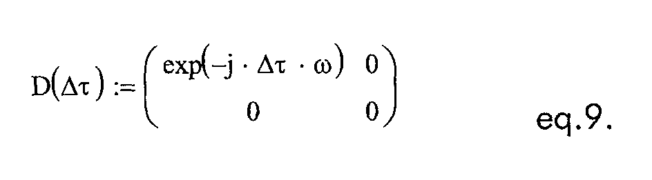
The birefringence PMF with a differential group delay Δτ (e.g. 50ps for 10Gb/s signals) and an angel of the principal polarization state has a Jones matrix :
- Two ways are possible for finding the appropriate PC parameters pik which minimize the CD and the PMD distortion:
- i) With the input signal CD and PMD calculated in conjunction with the feedback signal measurements, the setting pik of the PCs can be commanded via a look-up table, which has been generated by simulation or by experiments. This might only be applicable for pure CD compensation.
- ii) With the input signal CD and PMD calculated in conjunction with the feedback
signal measurements, the setting pik of the PCs can be found in by numerical iteration.
An example is explained below:
- With input PMD and CD the parameters αin(ω) and ϕin(ω) are known.
- With these values for every PC setting pik the output values α'(ω,p) and ϕ'(ω,p) can be calculated (Eq. 4+5).
- Moreover, with a target CD (given by the CD adaptation algorithm) and minimum PMD of the signal at the output, also target values of the polarization spectrum and phase spectrum can be calculated: αC(ω) and ϕC(ω).
- The setting of the compensator pik can be varied in an iterative process to minimize the differences simultaneously: |αC(ω)-α'(ω,p) | and |ϕC(ω) - ϕ'(ω,p)|. It might be advantageous to weight the differences by the amplitude spectrum or the power spectrum |b(ω)| or b2(ω), respectively. These values can be measured or estimated for the signal.
-
Claims (4)
- A method for performing optical dispersion compensation of wavelength division multiplexed WDM optical signals, the method comprising the steps of:the method being characterized by the further steps of:providing a compensation stage with an optical transmission medium used as parallel operating cascade of polarization controllers and optical birefringent elements to compensate dispersion of the WDM optical signals when being transmitted spectrally dispersed into the different wavelength channels through the parallel arranged polarization controllers;determining the polarization states of each wavelength channel's different spectral components of the optical signals at all the different wavelength channel;defining accordingly a feedback signal (FB(ch), FB1(ch)) required for the polarization controllers setting when compensating in parallel the polarization mode dispersion at each different wavelength channel;determining the chromatic dispersion of the optical signals at one or few different wavelength channels allowing an extrapolation of the chromatic dispersion to the other wavelength channels;defining accordingly a feedback signal (FB2, FB4) required when compensating in parallel the chromatic dispersion at each different wavelength channel;calculating the polarization controller setting per wavelength channel using feedback signals obtained from both polarization mode dispersion (FB(ch), FB1(ch)) and chromatic dispersion (FB2, FB4);applying in parallel the respective setting on the polarization controllers to compensate optical dispersion of the WDM optical signals at each different wavelength channel.
- The method for performing optical dispersion compensation according to claim 1 characterized by determining the chromatic dispersion with the measure of some WDM optical signals quality at one of few different wavelength channels.
- The method for performing optical dispersion compensation according to claim 2 characterized by varying the polarization controller setting per wavelength channel using the chromatic dispersion feedback signal (FB2, FB4) such to obtain an improved signal quality while keeping the polarization mode dispersion compensation property of the WDM optical signal almost to an optimum value.
- A computer readable medium having a computer program recorded thereon, the computer program comprising codes adapted to perform a procedure when said computer program is run on a control unit for an optical transmission medium to be used as polarization controllers to compensate dispersion of wavelength division multiplexed WDM optical signals, while the procedure performing the step of:the procedure being characterized by the further steps of:collecting feedback signal (FB(ch), FB1(ch)) required for the polarization controllers setting when compensating in parallel the polarization mode dispersion at each different wavelength channel of the WDM optical signals when being transmitted spectrally dispersed into the different wavelength channels through the parallel arranged polarization controllers;collecting feedback signal (FB2, FB4) required when compensating in parallel the chromatic dispersion at each different wavelength channel;calculating the polarization controller setting per wavelength channel using feedback signals obtained from both polarization mode dispersion (FB(ch), FB1(ch)) and chromatic dispersion (FB2, FB4);applying in parallel the respective setting on the polarization controllers to compensate optical dispersion of the WDM optical signals at each different wavelength channel.
Priority Applications (5)
| Application Number | Priority Date | Filing Date | Title |
|---|---|---|---|
| EP04292626A EP1598963B1 (en) | 2004-05-17 | 2004-11-05 | Multi-wavelength CD and PMD compensator |
| US11/097,325 US7257290B2 (en) | 2004-05-17 | 2005-04-04 | Multi-wavelength CD and PMD compensator |
| RU2005141140/09A RU2005141140A (en) | 2004-05-17 | 2005-05-12 | MULTI-WAVE CD AND PMD COMPENSATOR |
| MXPA05013258A MXPA05013258A (en) | 2004-05-17 | 2005-05-12 | Multi-wavelength cd and pmd compensator. |
| PCT/EP2005/052172 WO2005112310A1 (en) | 2004-05-17 | 2005-05-12 | Multi-wavelength cd and pmd compensator |
Applications Claiming Priority (3)
| Application Number | Priority Date | Filing Date | Title |
|---|---|---|---|
| EP04291260 | 2004-05-17 | ||
| EP04291260 | 2004-05-17 | ||
| EP04292626A EP1598963B1 (en) | 2004-05-17 | 2004-11-05 | Multi-wavelength CD and PMD compensator |
Publications (2)
| Publication Number | Publication Date |
|---|---|
| EP1598963A1 true EP1598963A1 (en) | 2005-11-23 |
| EP1598963B1 EP1598963B1 (en) | 2006-09-27 |
Family
ID=34967781
Family Applications (1)
| Application Number | Title | Priority Date | Filing Date |
|---|---|---|---|
| EP04292626A Expired - Lifetime EP1598963B1 (en) | 2004-05-17 | 2004-11-05 | Multi-wavelength CD and PMD compensator |
Country Status (5)
| Country | Link |
|---|---|
| US (1) | US7257290B2 (en) |
| EP (1) | EP1598963B1 (en) |
| MX (1) | MXPA05013258A (en) |
| RU (1) | RU2005141140A (en) |
| WO (1) | WO2005112310A1 (en) |
Families Citing this family (9)
| Publication number | Priority date | Publication date | Assignee | Title |
|---|---|---|---|---|
| ITMI20040446A1 (en) * | 2004-03-09 | 2004-06-09 | Marconi Comm Spa | METHOD AND APPARATUS SYSTEM FOR COMPENSATION OF PMD AND CONTEMPORARY DEMULTIPLATION OF PAIRS OF MULTIPLE SIGNALS ION POLARIZATION |
| DE602004020595D1 (en) * | 2004-05-19 | 2009-05-28 | Alcatel Lucent | Method for controlling an optical transmission and reception system with bit-wise alternating polarization of a bit stream |
| EP2005621A1 (en) * | 2005-12-29 | 2008-12-24 | Ericsson Telecomunicaçoes S.A. | Method and arrangement for polarization mode dispersion mitigation |
| DE102006045133A1 (en) * | 2006-09-25 | 2008-04-10 | Nokia Siemens Networks Gmbh & Co.Kg | Arrangement for setting and compensating polarization mode dispersion of first and second order |
| US8073326B2 (en) * | 2006-12-06 | 2011-12-06 | General Photonics Corporation | Optical polarization division multiplexing in optical communication |
| US20090067783A1 (en) * | 2007-09-07 | 2009-03-12 | Azea Networks Limited | Method of tuning an adjustable dispersion compensator |
| US8463141B2 (en) * | 2007-09-14 | 2013-06-11 | Alcatel Lucent | Reconstruction and restoration of two polarization components of an optical signal field |
| JP6878979B2 (en) * | 2017-03-22 | 2021-06-02 | 富士通株式会社 | Communication device and transmission signal control method |
| US11095390B2 (en) * | 2018-08-23 | 2021-08-17 | International Business Machines Corporation | Polarization-insensitive optical link |
Citations (4)
| Publication number | Priority date | Publication date | Assignee | Title |
|---|---|---|---|---|
| WO2002080411A1 (en) * | 2001-03-19 | 2002-10-10 | Terapulse, Inc. | Polarization mode dispersion compensation in optical transmission media |
| WO2003040777A2 (en) * | 2001-11-02 | 2003-05-15 | Worldcom, Inc. | Integrated adaptive chromatic dispersion/polarization mode dispersion compensation system |
| US20030223056A1 (en) * | 2002-05-31 | 2003-12-04 | Xiaoli Fu | Optical circuits for tunable second order PMD compensation and tunable dispersion compensation |
| US6710904B1 (en) * | 1999-07-08 | 2004-03-23 | Alcatel | System for compensating polarization dispersion in an optical transmission system |
Family Cites Families (2)
| Publication number | Priority date | Publication date | Assignee | Title |
|---|---|---|---|---|
| FR2791835B1 (en) * | 1999-03-31 | 2001-06-29 | Cit Alcatel | DEVICE AND METHOD FOR COMPENSATING FOR POLARIZATION DISPERSION IN AN OPTICAL TRANSMISSION SYSTEM |
| US6778782B1 (en) * | 2000-09-27 | 2004-08-17 | Nortel Networks Limited | Dispersion compensation |
-
2004
- 2004-11-05 EP EP04292626A patent/EP1598963B1/en not_active Expired - Lifetime
-
2005
- 2005-04-04 US US11/097,325 patent/US7257290B2/en not_active Expired - Fee Related
- 2005-05-12 RU RU2005141140/09A patent/RU2005141140A/en not_active Application Discontinuation
- 2005-05-12 MX MXPA05013258A patent/MXPA05013258A/en unknown
- 2005-05-12 WO PCT/EP2005/052172 patent/WO2005112310A1/en not_active Ceased
Patent Citations (4)
| Publication number | Priority date | Publication date | Assignee | Title |
|---|---|---|---|---|
| US6710904B1 (en) * | 1999-07-08 | 2004-03-23 | Alcatel | System for compensating polarization dispersion in an optical transmission system |
| WO2002080411A1 (en) * | 2001-03-19 | 2002-10-10 | Terapulse, Inc. | Polarization mode dispersion compensation in optical transmission media |
| WO2003040777A2 (en) * | 2001-11-02 | 2003-05-15 | Worldcom, Inc. | Integrated adaptive chromatic dispersion/polarization mode dispersion compensation system |
| US20030223056A1 (en) * | 2002-05-31 | 2003-12-04 | Xiaoli Fu | Optical circuits for tunable second order PMD compensation and tunable dispersion compensation |
Also Published As
| Publication number | Publication date |
|---|---|
| MXPA05013258A (en) | 2006-03-09 |
| EP1598963B1 (en) | 2006-09-27 |
| US20050254749A1 (en) | 2005-11-17 |
| US7257290B2 (en) | 2007-08-14 |
| RU2005141140A (en) | 2007-07-10 |
| WO2005112310A1 (en) | 2005-11-24 |
Similar Documents
| Publication | Publication Date | Title |
|---|---|---|
| US8260092B2 (en) | Systems and methods for polarization mode dispersion mitigation | |
| CA2362893A1 (en) | Method and apparatus for providing high-order polarization mode dispersion compensation using temporal imaging | |
| US6765670B2 (en) | Spectrometer module and applications thereof | |
| US20080159739A1 (en) | Polarization mode dispersion compensator, polarization mode dispersion compensating method, and its application to optical communication system | |
| US6646774B1 (en) | Intra-bit polarization diversity modulation | |
| US7106979B1 (en) | Polarization mode dispersion compensating apparatus, system, and method | |
| EP1598963B1 (en) | Multi-wavelength CD and PMD compensator | |
| Rasmussen et al. | Automatic compensation of polarization-mode dispersion for 40 Gb/s transmission systems | |
| US6889011B1 (en) | Integrated adaptive chromatic dispersion/polarization mode dispersion compensation system | |
| EP1530309A1 (en) | Polarization mode dispersion compensator, polarization mode dispersion compensating method, and its application to optical communication system | |
| US20060013592A1 (en) | Polarization mode dispersion compensation apparatus and method thereof in light wavelength division multiplexing transmission system | |
| CN100435504C (en) | Multi-wavelength Chromatic Dispersion (CD) and Polarization Mode Dispersion (PMD) Compensation Method | |
| JP4067527B2 (en) | Method and apparatus for providing controllable second-order polarization mode dispersion | |
| CN100592666C (en) | Methods for Higher Order Dispersion Compensation | |
| US6707587B1 (en) | Method and apparatus for providing tunable second-order polarization mode dispersion with constant mean first-order differential group delay | |
| Mimura et al. | PMD compensator and PMD emulator | |
| CN1322690C (en) | A method of polarization mode dispersion compensation | |
| Yi et al. | Optical device for PMD compensation by using high-birefringence linear chirped grating | |
| Wang et al. | Non-intrusive estimation of PMD-induced penalty via high speed, high resolution spectral polarimeter | |
| Pilichi | PMD impairments in optical fiber transmission at 10 Gbps and 40 Gbps | |
| Targove et al. | Multichannel optical PMD compensator | |
| JP2004271277A (en) | Polarization dispersion analysis method, apparatus thereof, and polarization dispersion compensating apparatus | |
| Boehm et al. | Methods for in-service measurement of polarization mode dispersion | |
| Simões et al. | Dynamic monochannel first-order polarization mode dispersion compensation through downhill simplex optimization | |
| Yaffe et al. | Important advances in PMD tolerance quantification for next-generation lightwave systems |
Legal Events
| Date | Code | Title | Description |
|---|---|---|---|
| PUAI | Public reference made under article 153(3) epc to a published international application that has entered the european phase |
Free format text: ORIGINAL CODE: 0009012 |
|
| 17P | Request for examination filed |
Effective date: 20050809 |
|
| AK | Designated contracting states |
Kind code of ref document: A1 Designated state(s): AT BE BG CH CY CZ DE DK EE ES FI FR GB GR HU IE IS IT LI LU MC NL PL PT RO SE SI SK TR |
|
| AX | Request for extension of the european patent |
Extension state: AL HR LT LV MK YU |
|
| GRAP | Despatch of communication of intention to grant a patent |
Free format text: ORIGINAL CODE: EPIDOSNIGR1 |
|
| GRAS | Grant fee paid |
Free format text: ORIGINAL CODE: EPIDOSNIGR3 |
|
| AKX | Designation fees paid |
Designated state(s): AT BE BG CH CY CZ DE DK EE ES FI FR GB GR HU IE IS IT LI LU MC NL PL PT RO SE SI SK TR |
|
| GRAA | (expected) grant |
Free format text: ORIGINAL CODE: 0009210 |
|
| AK | Designated contracting states |
Kind code of ref document: B1 Designated state(s): AT BE BG CH CY CZ DE DK EE ES FI FR GB GR HU IE IS IT LI LU MC NL PL PT RO SE SI SK TR |
|
| PG25 | Lapsed in a contracting state [announced via postgrant information from national office to epo] |
Ref country code: IT Free format text: LAPSE BECAUSE OF FAILURE TO SUBMIT A TRANSLATION OF THE DESCRIPTION OR TO PAY THE FEE WITHIN THE PRESCRIBED TIME-LIMIT;WARNING: LAPSES OF ITALIAN PATENTS WITH EFFECTIVE DATE BEFORE 2007 MAY HAVE OCCURRED AT ANY TIME BEFORE 2007. THE CORRECT EFFECTIVE DATE MAY BE DIFFERENT FROM THE ONE RECORDED. Effective date: 20060927 Ref country code: AT Free format text: LAPSE BECAUSE OF FAILURE TO SUBMIT A TRANSLATION OF THE DESCRIPTION OR TO PAY THE FEE WITHIN THE PRESCRIBED TIME-LIMIT Effective date: 20060927 Ref country code: SI Free format text: LAPSE BECAUSE OF FAILURE TO SUBMIT A TRANSLATION OF THE DESCRIPTION OR TO PAY THE FEE WITHIN THE PRESCRIBED TIME-LIMIT Effective date: 20060927 Ref country code: BE Free format text: LAPSE BECAUSE OF FAILURE TO SUBMIT A TRANSLATION OF THE DESCRIPTION OR TO PAY THE FEE WITHIN THE PRESCRIBED TIME-LIMIT Effective date: 20060927 Ref country code: SK Free format text: LAPSE BECAUSE OF FAILURE TO SUBMIT A TRANSLATION OF THE DESCRIPTION OR TO PAY THE FEE WITHIN THE PRESCRIBED TIME-LIMIT Effective date: 20060927 Ref country code: NL Free format text: LAPSE BECAUSE OF FAILURE TO SUBMIT A TRANSLATION OF THE DESCRIPTION OR TO PAY THE FEE WITHIN THE PRESCRIBED TIME-LIMIT Effective date: 20060927 Ref country code: CH Free format text: LAPSE BECAUSE OF FAILURE TO SUBMIT A TRANSLATION OF THE DESCRIPTION OR TO PAY THE FEE WITHIN THE PRESCRIBED TIME-LIMIT Effective date: 20060927 Ref country code: RO Free format text: LAPSE BECAUSE OF FAILURE TO SUBMIT A TRANSLATION OF THE DESCRIPTION OR TO PAY THE FEE WITHIN THE PRESCRIBED TIME-LIMIT Effective date: 20060927 Ref country code: CZ Free format text: LAPSE BECAUSE OF FAILURE TO SUBMIT A TRANSLATION OF THE DESCRIPTION OR TO PAY THE FEE WITHIN THE PRESCRIBED TIME-LIMIT Effective date: 20060927 Ref country code: LI Free format text: LAPSE BECAUSE OF FAILURE TO SUBMIT A TRANSLATION OF THE DESCRIPTION OR TO PAY THE FEE WITHIN THE PRESCRIBED TIME-LIMIT Effective date: 20060927 Ref country code: FI Free format text: LAPSE BECAUSE OF FAILURE TO SUBMIT A TRANSLATION OF THE DESCRIPTION OR TO PAY THE FEE WITHIN THE PRESCRIBED TIME-LIMIT Effective date: 20060927 Ref country code: PL Free format text: LAPSE BECAUSE OF FAILURE TO SUBMIT A TRANSLATION OF THE DESCRIPTION OR TO PAY THE FEE WITHIN THE PRESCRIBED TIME-LIMIT Effective date: 20060927 |
|
| REG | Reference to a national code |
Ref country code: GB Ref legal event code: FG4D |
|
| REG | Reference to a national code |
Ref country code: CH Ref legal event code: EP |
|
| REG | Reference to a national code |
Ref country code: IE Ref legal event code: FG4D |
|
| PG25 | Lapsed in a contracting state [announced via postgrant information from national office to epo] |
Ref country code: IE Free format text: LAPSE BECAUSE OF NON-PAYMENT OF DUE FEES Effective date: 20061106 |
|
| REF | Corresponds to: |
Ref document number: 602004002573 Country of ref document: DE Date of ref document: 20061109 Kind code of ref document: P |
|
| PG25 | Lapsed in a contracting state [announced via postgrant information from national office to epo] |
Ref country code: MC Free format text: LAPSE BECAUSE OF NON-PAYMENT OF DUE FEES Effective date: 20061130 |
|
| PG25 | Lapsed in a contracting state [announced via postgrant information from national office to epo] |
Ref country code: DK Free format text: LAPSE BECAUSE OF FAILURE TO SUBMIT A TRANSLATION OF THE DESCRIPTION OR TO PAY THE FEE WITHIN THE PRESCRIBED TIME-LIMIT Effective date: 20061227 Ref country code: SE Free format text: LAPSE BECAUSE OF FAILURE TO SUBMIT A TRANSLATION OF THE DESCRIPTION OR TO PAY THE FEE WITHIN THE PRESCRIBED TIME-LIMIT Effective date: 20061227 Ref country code: BG Free format text: LAPSE BECAUSE OF FAILURE TO SUBMIT A TRANSLATION OF THE DESCRIPTION OR TO PAY THE FEE WITHIN THE PRESCRIBED TIME-LIMIT Effective date: 20061227 |
|
| PG25 | Lapsed in a contracting state [announced via postgrant information from national office to epo] |
Ref country code: ES Free format text: LAPSE BECAUSE OF FAILURE TO SUBMIT A TRANSLATION OF THE DESCRIPTION OR TO PAY THE FEE WITHIN THE PRESCRIBED TIME-LIMIT Effective date: 20070107 |
|
| PG25 | Lapsed in a contracting state [announced via postgrant information from national office to epo] |
Ref country code: IS Free format text: LAPSE BECAUSE OF FAILURE TO SUBMIT A TRANSLATION OF THE DESCRIPTION OR TO PAY THE FEE WITHIN THE PRESCRIBED TIME-LIMIT Effective date: 20070127 |
|
| NLV1 | Nl: lapsed or annulled due to failure to fulfill the requirements of art. 29p and 29m of the patents act | ||
| PG25 | Lapsed in a contracting state [announced via postgrant information from national office to epo] |
Ref country code: PT Free format text: LAPSE BECAUSE OF FAILURE TO SUBMIT A TRANSLATION OF THE DESCRIPTION OR TO PAY THE FEE WITHIN THE PRESCRIBED TIME-LIMIT Effective date: 20070313 |
|
| ET | Fr: translation filed | ||
| RAP2 | Party data changed (patent owner data changed or rights of a patent transferred) |
Owner name: ALCATEL LUCENT |
|
| REG | Reference to a national code |
Ref country code: CH Ref legal event code: PL |
|
| PLBE | No opposition filed within time limit |
Free format text: ORIGINAL CODE: 0009261 |
|
| STAA | Information on the status of an ep patent application or granted ep patent |
Free format text: STATUS: NO OPPOSITION FILED WITHIN TIME LIMIT |
|
| 26N | No opposition filed |
Effective date: 20070628 |
|
| PG25 | Lapsed in a contracting state [announced via postgrant information from national office to epo] |
Ref country code: GR Free format text: LAPSE BECAUSE OF FAILURE TO SUBMIT A TRANSLATION OF THE DESCRIPTION OR TO PAY THE FEE WITHIN THE PRESCRIBED TIME-LIMIT Effective date: 20061228 |
|
| PG25 | Lapsed in a contracting state [announced via postgrant information from national office to epo] |
Ref country code: EE Free format text: LAPSE BECAUSE OF FAILURE TO SUBMIT A TRANSLATION OF THE DESCRIPTION OR TO PAY THE FEE WITHIN THE PRESCRIBED TIME-LIMIT Effective date: 20060927 |
|
| PG25 | Lapsed in a contracting state [announced via postgrant information from national office to epo] |
Ref country code: TR Free format text: LAPSE BECAUSE OF FAILURE TO SUBMIT A TRANSLATION OF THE DESCRIPTION OR TO PAY THE FEE WITHIN THE PRESCRIBED TIME-LIMIT Effective date: 20060927 Ref country code: HU Free format text: LAPSE BECAUSE OF FAILURE TO SUBMIT A TRANSLATION OF THE DESCRIPTION OR TO PAY THE FEE WITHIN THE PRESCRIBED TIME-LIMIT Effective date: 20070328 Ref country code: LU Free format text: LAPSE BECAUSE OF NON-PAYMENT OF DUE FEES Effective date: 20061105 |
|
| PG25 | Lapsed in a contracting state [announced via postgrant information from national office to epo] |
Ref country code: CY Free format text: LAPSE BECAUSE OF FAILURE TO SUBMIT A TRANSLATION OF THE DESCRIPTION OR TO PAY THE FEE WITHIN THE PRESCRIBED TIME-LIMIT Effective date: 20060927 |
|
| PGFP | Annual fee paid to national office [announced via postgrant information from national office to epo] |
Ref country code: IT Payment date: 20101125 Year of fee payment: 7 |
|
| PG25 | Lapsed in a contracting state [announced via postgrant information from national office to epo] |
Ref country code: IT Free format text: LAPSE BECAUSE OF NON-PAYMENT OF DUE FEES Effective date: 20111105 |
|
| REG | Reference to a national code |
Ref country code: FR Ref legal event code: GC Effective date: 20140717 |
|
| REG | Reference to a national code |
Ref country code: FR Ref legal event code: RG Effective date: 20141016 |
|
| PGFP | Annual fee paid to national office [announced via postgrant information from national office to epo] |
Ref country code: GB Payment date: 20141119 Year of fee payment: 11 Ref country code: DE Payment date: 20141119 Year of fee payment: 11 Ref country code: FR Payment date: 20141119 Year of fee payment: 11 |
|
| REG | Reference to a national code |
Ref country code: FR Ref legal event code: CA Effective date: 20150521 |
|
| REG | Reference to a national code |
Ref country code: FR Ref legal event code: CA Effective date: 20150521 |
|
| REG | Reference to a national code |
Ref country code: DE Ref legal event code: R119 Ref document number: 602004002573 Country of ref document: DE |
|
| GBPC | Gb: european patent ceased through non-payment of renewal fee |
Effective date: 20151105 |
|
| REG | Reference to a national code |
Ref country code: FR Ref legal event code: ST Effective date: 20160729 |
|
| PG25 | Lapsed in a contracting state [announced via postgrant information from national office to epo] |
Ref country code: DE Free format text: LAPSE BECAUSE OF NON-PAYMENT OF DUE FEES Effective date: 20160601 Ref country code: GB Free format text: LAPSE BECAUSE OF NON-PAYMENT OF DUE FEES Effective date: 20151105 |
|
| PG25 | Lapsed in a contracting state [announced via postgrant information from national office to epo] |
Ref country code: FR Free format text: LAPSE BECAUSE OF NON-PAYMENT OF DUE FEES Effective date: 20151130 |