EP1598949A2 - Electronic security system - Google Patents
Electronic security system Download PDFInfo
- Publication number
- EP1598949A2 EP1598949A2 EP05253011A EP05253011A EP1598949A2 EP 1598949 A2 EP1598949 A2 EP 1598949A2 EP 05253011 A EP05253011 A EP 05253011A EP 05253011 A EP05253011 A EP 05253011A EP 1598949 A2 EP1598949 A2 EP 1598949A2
- Authority
- EP
- European Patent Office
- Prior art keywords
- power supply
- electronic security
- psm
- supply module
- devices
- Prior art date
- Legal status (The legal status is an assumption and is not a legal conclusion. Google has not performed a legal analysis and makes no representation as to the accuracy of the status listed.)
- Withdrawn
Links
- 238000000034 method Methods 0.000 claims description 22
- 238000004891 communication Methods 0.000 claims description 15
- 230000008878 coupling Effects 0.000 claims description 8
- 238000010168 coupling process Methods 0.000 claims description 8
- 238000005859 coupling reaction Methods 0.000 claims description 8
- 230000002093 peripheral effect Effects 0.000 claims description 5
- 229920003259 poly(silylenemethylene) Polymers 0.000 description 122
- 238000002345 optical interference microscopy Methods 0.000 description 106
- 230000008569 process Effects 0.000 description 11
- 230000009471 action Effects 0.000 description 9
- 230000006870 function Effects 0.000 description 9
- 238000010586 diagram Methods 0.000 description 8
- 238000012360 testing method Methods 0.000 description 8
- 238000013507 mapping Methods 0.000 description 7
- 238000012546 transfer Methods 0.000 description 6
- 239000000872 buffer Substances 0.000 description 4
- 238000001914 filtration Methods 0.000 description 4
- 238000013024 troubleshooting Methods 0.000 description 4
- YJWDKWRVFJZBCJ-QVJDATKISA-N (4r,4as,7ar,12bs)-4a,9-dihydroxy-3-methylspiro[1,2,4,5,7a,13-hexahydro-4,12-methanobenzofuro[3,2-e]isoquinoline-6,2'-1,3-dihydroindene]-7-one Chemical compound C1C2=CC=CC=C2CC1(C([C@@H]1O2)=O)C[C@@]3(O)[C@H]4CC5=CC=C(O)C2=C5[C@@]13CCN4C YJWDKWRVFJZBCJ-QVJDATKISA-N 0.000 description 3
- 230000003321 amplification Effects 0.000 description 3
- 238000001514 detection method Methods 0.000 description 3
- 238000003199 nucleic acid amplification method Methods 0.000 description 3
- 238000013461 design Methods 0.000 description 2
- 238000009434 installation Methods 0.000 description 2
- 238000007726 management method Methods 0.000 description 2
- 230000004044 response Effects 0.000 description 2
- 230000000007 visual effect Effects 0.000 description 2
- 241000904454 Thespis Species 0.000 description 1
- 239000008186 active pharmaceutical agent Substances 0.000 description 1
- 238000012550 audit Methods 0.000 description 1
- 230000005540 biological transmission Effects 0.000 description 1
- 230000008859 change Effects 0.000 description 1
- 230000000694 effects Effects 0.000 description 1
- 238000004519 manufacturing process Methods 0.000 description 1
- 238000011022 operating instruction Methods 0.000 description 1
- 230000000737 periodic effect Effects 0.000 description 1
- 238000012545 processing Methods 0.000 description 1
- 230000001105 regulatory effect Effects 0.000 description 1
- 238000010187 selection method Methods 0.000 description 1
Images


Classifications
-
- H—ELECTRICITY
- H04—ELECTRIC COMMUNICATION TECHNIQUE
- H04B—TRANSMISSION
- H04B3/00—Line transmission systems
- H04B3/54—Systems for transmission via power distribution lines
-
- H—ELECTRICITY
- H04—ELECTRIC COMMUNICATION TECHNIQUE
- H04B—TRANSMISSION
- H04B2203/00—Indexing scheme relating to line transmission systems
- H04B2203/54—Aspects of powerline communications not already covered by H04B3/54 and its subgroups
- H04B2203/5429—Applications for powerline communications
- H04B2203/5458—Monitor sensor; Alarm systems
Definitions
- the present invention relates to electronic security systems and particularly to security systems that use electronic locks and other security devices to secure a building.
- Common functions of typical electronic security systems include sounding alarms on forced entry, limiting access to those who possess the appropriate credentials, and sounding alarms if doors are held open too long or do not close properly.
- Other common electronic security system functions include limiting the number of doors that can be opened at a given time (interlocks), and applying timing values to particular operations to hold occupants in a building for a selected time or lock or unlock doors from a remote location.
- the conventional electronic architectural products that perform these functions can have many wires or connection points. Understanding these components and how they are to be wired to perform the desired functionality adds to the complexity of conventional systems. As mentioned, complex issues arise again if it is ever desired to reconfigure the system.
- the present invention provides for an electronic security system which includes a plurality of security devices electrically linked to a power supply over a series of power lines. Each device is coupled to the power lines with two wires. The devices and power supply also utilize the power lines to send and receive communication signals.
- an electronic security system comprising a plurality of electronic security devices, each including an input/output module, which receives and decodes electronic signals and governs the functionality of the electronic security device; and a power supply, which sends electrical power to the plurality of electronic security devices over power lines, the power supply including a power supply module, which contains a program dictating the functionality of the system, the power supply module sending signals to and receiving signals from the input/output modules over the power lines.
- an electronic security system comprising a power supply having exactly two power supply terminals; a plurality of electronic security devices, each having exactly two security device terminals; a first wire coupling together one of the terminals of the power supply and one of the terminals of each of the plurality of electronic security devices; and a second wire coupling together the other of the terminals of the power supply and the other of the terminals of each of the plurality of electronic security devices.
- a method of establishing an electronic security system comprising the steps of establishing a power supply having a power supply module; electrically connecting exactly two terminals of a first electronic security device to the power supply; electrically connecting exactly two terminals of a second electronic security device to the power supply; and uploading a program onto the power supply module to configure the functionality of the first and second electronic security devices.
- a method of establishing a programmable electronic security system comprising the steps of electrically connecting a configuration tool to an electronic security device of a first programmable electronic security system and downloading a functionality program from the first programmable electronic security system onto the configuration tool; disconnecting the configuration tool from the electronic security device; and uploading the first programmable electronic security system functionality program from the configuration tool onto a second programmable electronic security system.
- each security device includes an input/output module ("I/O module”), which controls the device.
- the power supply includes a power supply module ("PSM”) which receives the master functionality program for the system. Once the PSM is programmed with the desired functionality for the system, it sends signals over the power lines to the I/O modules of the various security devices, programming them according to the desired functionality.
- a bus through which the power lines to each device run, controls the communication signals between the devices.
- the devices of the electronic security system can be configured in a star pattern, wherein each device is tied into a central connection point, in a daisy chain arrangement, wherein the devices are strung together, or a combination of both arrangements.
- FIG. 1 shows a block diagram view of an example of a 2-wire electronic security system 100.
- the 2-wire electronic security system 100 includes a 2-wire power supply (“PS") 104 coupled to a plurality of input output modules (“IOMs") 120 via a 2-wire bus 116.
- a programming tool, or a configuration tool 132 in the form of a computer, a personal pocket computer, or a handheld computer can be also coupled to the PS 104 either directly via a serial link 130, or indirectly through a 2-wire interface 133 and the bus 116.
- the IOMs 120 are further coupled to a plurality of architectural devices or electronic security devices 108.
- security devices 108 include sensors, horns, shear locks, magnetic locks, electric strikes, actuators, buttons, motion sensors, door positioning switches, electric locks, exit devices, desk consoles, monitor strikes, magnetic switch, key switches, keypads, card readers and the like.
- devices 108 are existing non-2-wire devices.
- external IOMs 120 provide linkages between the devices 108 and the bus 116, thus allowing exchange of data between the PS 104 and the devices 108.
- Devices 110 are shown as 2-wire devices that are to be coupled to the bus 116 directly. That is, devices 110 are generally manufactured specifically for use in a 2-wire system such as system 100. These devices 110 generally have an internal IOM 120 such as shown in FIG. 3.
- the PS 104 also includes a power supply module (“PSM”) 112 configured to manage the operation of the system 100.
- the PS 104 includes a power supply PLC modem or a power supply module (“PSM”) 112 that manages and communicates with the IOMs 120 via the 2-wire bus 116.
- the 2-wire bus 116 In addition to carrying configuration signals or instructions, the 2-wire bus 116 also carries power from the PS 104 to the IOMs 120 in the system 100.
- the PSM 112 is also equipped with a timing circuit that can be used as a time reference by the rest of the system 100, and an application-specific integrated circuit ("ASIC") 260 that includes a power failure detection circuit 264.
- ASIC application-specific integrated circuit
- the power failure detection circuit 264 senses or monitors an incoming supply voltage level. If the incoming supply voltage level falls below a predetermined value, the ASIC 260 will generate a warning signal indicating an impending power failure.
- the ASIC 260 also accesses an internal memory 252 or an external memory 262 for a configuration that governs the system 100.
- the ASIC 260 first decodes the configuration from the memory 252 or 262, processes and modulates the power with the configuration using schemes such as frequency shift keying modulation.
- the ASIC 260 then amplifies and buffers the configuration modulated signal to prepare for outputting to the 2-wire bus 116.
- the ASIC 260 then transmits the signal to the IOMs 120 via the 2-wire bus 116.
- other sequences of transmission are also possible.
- the PSM 112 also includes a 2-wire bus switching circuit 263 that is controlled by the ASIC 260.
- the ASIC 260 controls the power present on the bus 116 via the 2-wire bus switching circuit 263.
- the 2-wire bus switching circuit 263 is turned off by the ASIC 260, such that the relay is open.
- the 2-wire bus switching circuit 263 will be turned on when the ASIC 260 outputs the power in conjunction with the signal.
- the system 100 also allows other external processors and other peripherals to be coupled to the PSM 112 for special purposes, such as additional processing power and special input output (“I/O") combinations.
- the PS 104 has a plurality of serial peripheral interface ("SPI") ports 124. Each port 124 is separately selected by a select signal from the ASIC 260.
- the PS 104 is also configured to be able to provide the external peripherals with different current voltage signals, and different data transfer rates.
- One of the SPI ports 124 includes a PSM-to-PSM communication interface port 232 that is configured to allow communications between a plurality of PSMs 104, or PSM-to-PSM communications via a twisted pair wiring network.
- the ASIC 260 of one system can be coupled to the ASIC 260 of another system via the PSM-to-PSM communication port 232 of the SPI ports 124 to allow relatively fast transfer of information between the PSMs 112.
- the PSM-to-PSM communication interface port 232 also provides the necessary power amplification to drive any low-impedance load that can appear on the PSM-to-PSM communication interface port bus.
- the ASIC 260 can be programmed either via a serial TTL RS-232 port 130 of the PS 104, or can be programmed in the manufacturing process. Once a program has been programmed in the ASIC 260, it may be upgraded via the 2-wire bus 116 or the serial port 130.
- the programming of the PSM 112, and in particular, the ASIC 260 is detailed hereinafter.
- a plurality of input filters 266 are coupled to the ASIC 260 and the SPI interface ports 124 including the PSM-to-PSM communication interface port 236.
- the input filters 266 increase a signal-to-noise ratio at the inputs of the ASIC 260 by filtering out anything outside a predetermined frequency range, for example, between 110 kHz to 130 kHz.
- the input filters 266 are generally Chebyshev type passive filters of the 4th order, with less than 1dB ripple at its output and about 6dB attenuation. However, filters such as the Butterworth filters that satisfy the filtering characteristics can also be used.
- a coupling circuit 268 bridges between the interface ports 124, 232 and the ASIC 260 to allow non-polarisation of the SPI interface ports 124.
- devices 108, 110 are generally configured by the PSM 112 (detailed hereinafter), or by the programming tool 132.
- PSM 112 the programming tool
- other PSMs, or programming tools can access the PSM 112 via the SPIs 124. Once access is permitted, system configuration stored in the PSM 112 and other system diagnostic operations can be updated and performed.
- the system 100 also allows for adding devices 108 or 110 into the system 100 without the need for any programming tools.
- the PSM 112 automatically detects the presence of a new device (for example, device 110), and configures the new device.
- the power supply 104 incorporating the PSM 112 provides functions such as detecting the presence of new devices and configuring the new device according to a particular functionality desired by the user.
- the PS 104 includes an alternating current ("AC") input port 204, and a plurality of main output ports configured to communicate with various devices (e.g., devices 108 and 110 in FIG. 1) and other power supplies (as discussed below with reference to FIG. 4).
- the PS 104 provides a 2-wire output port 212 through which the PSM 112 is coupled to the bus 116 (FIG. 1). More specifically, the 2-wire output port 212 includes exactly two terminals. Each terminal is coupled to an input terminal of the devices 108 via IOM 120, and 110.
- the remaining SPI communication port 124 is configured to couple the PS 104 to other networks, while a pocket personal computer (“ppc") port 244 is configured to couple the PS 104 to a handheld device such as a ppc.
- ppc port 244 provides a route other than the serial port 130 through which serial data or programming instructions can be entered.
- the PSM 112 also includes a memory area 252 that stores information regarding what devices 108, 110 and IOMs 120 are present in the system 100.
- an AC input LED 220 is lit indicating the PS 104 is powered.
- a transformer 224 is coupled to the AC input port 204, and provides multiple outputs. Each of the transformer outputs provides a particular AC voltage. The AC voltages are thereafter further rectified to obtain a plurality of direct current (“DC") voltages, which are supplied to the rest of the power supply 104.
- a battery board 228 continuously monitors the AC power input while a chargeable battery thereon is being charged. The battery board 228 via the chargeable battery supplies power to the PSM 112 in the event the AC power input is interrupted.
- the PSM 112 is also capable of data logging.
- Each PSM 112 has a segment of the memory 252 or 262 reserved for timed logging system data.
- Types of data to be logged include input changes, output changes, password changes, PSM resets, failures, etc.
- data such as a time of the day, the corresponding year, the device serial number, and the new input value are logged in the reserved memory.
- a password is changed (i.e., a password for a particular device, the overall network password, etc.), data such as the time of the day when the password is changed, the corresponding year, and the password is stored in the memory 252 or 262.
- the reserved memory also stores a cause of the PSM reset. As will be readily apparent, other data may also be logged if desired.
- IOM 120 Several types are used in the system 100, for example, a standard IOM (“SIOM”) and a high current IOM (“HIOM").
- SIOM standard IOM
- HIOM high current IOM
- FIG. 3 A generic IOM system block diagram 300 that describes installations such as SIOM and HIOM, is shown in FIG. 3.
- the generic IOM system 300 can either be a self-contained IOM configured to couple to a preexisting device 108, or internal to a device 110 specifically developed for the system 100.
- the IOM 120 has a plurality of input terminals 304 and output terminals 308.
- the inputs 304 are generally linked to security devices such as sensors, actuators, buttons, motion sensors, door positioning switches, or the like.
- the standard module (SIOM) will serve as the IOM and be configured to couple the device to the 2-wire bus 116.
- the high power module (HIOM), which supports a 16 Amp inrush current, will be used as the IOM to drive certain high current devices.
- Other types of IOM devices supported by the system 100 include high quantity IOM that provides a high number of inputs and outputs.
- the IOM 120 receives its power and programming signals via the 2-wire bus 116 and 2-wire power lines or 2-wire input terminals 334.
- Every IOM 120 in the system 100 has an internal timer. Upon powering up, each IOM 120 sends a time request command to the PSM 112. In response to the time request command, the PSM 112 sends out a time broadcast addressed to the IOM 120. In addition, the PSM 112 sends out a periodic time broadcast to all the IOMs 120 in the network to update the time being kept at the IOMs 120.
- the IOM system block diagram 300 also includes a second ASIC 316 that indirectly communicates with the 2-wire bus 116 via an IOM power supply 352 and an interface 332.
- the interface 332 is configured to modulate the output signals of the second ASIC 316, and to receive signals and instruction from other components in the system 100.
- the interface 332 also includes an output amplifier that provides power amplification to drive any low impedance loads that appear on the 2-wire bus 116. When it is not transmitting information, the amplifier is in low power mode.
- the amplifier further includes an input filter that increases the signal-to-noise ratio at the ASIC 316. The input filter filters out any signal that is outside a predefined frequency band.
- the filter does not attenuate the signal by more than a predefined amount in the desired bandwidth, and generally has a constant group delay.
- the amplifier also includes an output impedance control switch that isolates an output stage from the input filter when the amplifier is receiving.
- a bi-directional coupling circuit 344 bridges the interface 332 and the 2-wire bus 116.
- the second ASIC 316 can be programmed in a variety of ways via the 2-wire bus 116 and a SPI port 232. Once the ASIC 316 recognises that there is a programming signal, the ASIC 316 enters a programming mode, and awaits to receive data and instructions. When the programming signal is reset, the ASIC 316 terminates the data and instructions reception, and operates normally.
- the PSM 112 is also configured to manage the topology of the system 100.
- the PSM 112 has the attribute addresses to the devices, such as 108 and 110.
- a device list is located in the memory 252 or 262 of the PSM 112. For example, if a LOCK uses address 0xA0, the device list's 0xA0 entry will contain LOCK as a device type. The device list is very useful to rapidly discover every device on the system 100.
- every input and output (“I/O") in the system 100 has a unique identifier that is specified by an instance or an address.
- the PSM 112 assigns an address to the IOM 120
- the PSM 112 also assigns a unique instance for each input 304 and output 308.
- the I/O instance list of the PSM 120 can be used to associate devices and instances. Specifically, there is an entry in these lists for the input and output instances. The first element of the list is instance 1 and the last entry is the maximum number of instances allowed or available. For example, if an IOM 120 with address 0xA0 has 2 inputs, instance 1 and instance 2, the first two entries on the I/O instance list will be 0xA0 and 0 ⁇ A0.
- the PSM 112 assigns instances 3 and 4 to the IOM 120 with instance 0xA1
- the first four entries on the I/O instance list will look be 0xA0, 0xA0, 0xA1, and 0xA1.
- the PSM 112 keeps in the memory 252 or 262 a list of all the inputs and outputs of the IOMs 120 of the system 100.
- the I/O instance list stored in the memory 252 or 262 can be used to associate devices and instances. That is, for each input or output of the system 100, there is a corresponding entry in the I/O instance list.
- the application-specific integrated circuit (“ASIC") 316 of the IOM 120 directs the operations of the IOM 120.
- the ASIC 316 includes a plurality of I/O buffers 320 configured to send and receive data to and from other parts of the IOM 120.
- the ASIC 316 also includes a processor 324 that retrieves program instructions and data from a plurality of built-in memory modules 328.
- a memory decoder 330 of the IOM 120 then decodes the data and the instructions. Thereafter, the processor 324 modulates and processes the decoded instructions and data, executes the instructions according to an operating state of the system 100, and generates an output in response to a combination of the inputs and the operating state.
- the IOM 120 communicates with the PSM 112 via a 2-wire bus communication interface 332.
- the interface 332 provides functions including output signal amplification, output signal filtering, node input impedance control, input signal filtering.
- the interface 332 is bi-directionally coupled to the ASIC 316, and a power line coupler 344.
- the power line coupler 344 is bi-directionally coupled to one of the 2-wire power lines 334 which is further coupled to the 2-wire bus 116.
- the coupler 344 demodulates or decodes the modulated signal from inputs 334, or modulates or encodes data from the interface 332 onto the power lines 334.
- the user just needs to couple the 2-wire power lines 334 onto the bus 116 when a new 2-wire device such as device 110 is to be added to the system 100.
- the PSM 112 coupled to the bus 116 will thereafter start adding it onto its instance list (details are explained hereinafter).
- the 2-wire power lines 334 in addition to receiving the programmable logic among other information from the PSM 112, also carry the power for operation of the IOM 120.
- the power polarity of the connected devices may be different each time the device 108 or 110 is plugged into the system 100.
- a power bridge rectifier 348 is configured to accommodate any polarity.
- the polarity-desensitised or polarity independent power from the rectifier 348 is provided to the parts of the IOM 120 including a protected output 340 and a power down detection circuit 356.
- the rectified power from the rectifier 348 is also regulated in a power supply regulator 352.
- the IOM 120 also includes a plurality of input circuits 336.
- the inputs 304 are coupled to the input circuits 336, and the outputs of the input circuits 336 are fed to the I/O buffer 320 of the ASIC 316.
- the input circuits 336 are configured to sense the current voltage signal that is between 24 VDC and 0 VDC. While the circuit 336 provides an input voltage threshold, it also allows a maximum continuous input voltage that is higher than the input voltage threshold.
- the IOM 120 further includes a plurality of protected discrete general-purpose outputs 308 protected by a protection circuit 340.
- the protection circuit 340 receives its input from the processor 324 via the buffer 320 of the ASIC 316, its rectified power from a rectifier 348, and outputs an operating instruction to its associated device 108 or 110 through the outputs 308.
- the protection circuit 340 is activated for each output at a predefined threshold.
- a feedback circuit of the protection circuit 340 is configured to decrease the output current if excessive voltage or overcurrent is present at the outputs 308.
- the feedback circuit also sends a diagnostic signal to the ASIC 316 to signal whether any of the outputs 308 are shorted or opened.
- each output 308 is equipped with a thermal limit circuit, which senses a rise in a junction temperature associated with the overcurrent condition. If the overcurrent or short-circuit condition persists, the thermal limit circuit will turn off the corresponding faulty output 308. If a high power module is required, a high current inrush circuit 312 is added in series to the output 308 of the IOM 120.
- the PSM 112 can be similarly configured in a variety of methods. For example, if the PSM 112 does not contain any configuration data and is programmed by a user-interface configuration offline, there are three different configuration paths. Specifically, if the PSM 112 does not contain configuration data, the PSM 112 checks to determine if the programming tool 132 has been connected to the system 100 via the 2-wire 116. If the programming tool 132 has been connected, the pre-canned or preprogrammed configuration data stored in the programming tool 132 will be transferred or uploaded to the PSM 112. The PSM 112 then determines if there is any missing IOM that is not part of another 2-wire system.
- the PSM 112 will leave the existing IOMs 120 in a pre-canned pending state, and the programming tool 132, if still attached, displays that there are missing devices. The configuration process is reset and starts again. However, if all the IOMs 120 are present, the PSM 112 checks to see if there is any device duplication. If there is no duplication, the PSM 112 proceeds to transfer the configuration data loaded earlier on the IOMs 120 of the system 100. The system 100 is then configured. On the other hand, if there is device duplication, a user can resolve the duplication listed in the PSM 112 using the programming tool 132 as long as the programming tool 132 is still attached. The resolved configuration is then transferred to the IOMs 120, and the system 100 is configured.
- the programming tool 132 can be used to program the system 100 online.
- the programming tool 132 will direct a user to configure the PSM 112 and the system 100 using a user-interface wizard, which is detailed hereinafter.
- the configuration is thereafter transferred from the programming tool 132 to the PSM 112, and further into the IOMs 120.
- the system 100 is then configured.
- the programming tool 132 then proceeds to determine if the data is generic by checking for specific IOM serial numbers. If the PSM 112 does not contain specific IOM serial number, the programming tool 132 checks to determine if all the IOMs are present. If there is any IOM missing, the PSM 112 will leave the existing IOMs 120 in a pre-canned pending state, and the programming tool 132, if still attached, displays devices are missing. The configuration process is reset and starts again. If all the devices are present, the programming tool 132 then checks for device duplication. If there is no device duplication, the PSM 112 transfers the configuration data to the IOMs 120, and the system 100 is configured. However, if there is device duplication, the user can resolve the duplication listed in the PSM 112 using the programming tool 132 as long as the programming tool 132 is still attached. The resolved configuration is then transferred to the IOMs 120, and the system 100 is configured.
- the programming tool 132 again checks for missing IOM device. If there is missing device, the power is removed from the 2-wire bus 116. On the other hand, if all the devices are present, the PSM 112 then transfers the configuration data to the IOMs, and the system 100 is configured.
- the present invention allows for the PSM replacement without having to reprogram the system 100.
- the new PSM will check whether already-configured devices are found on the system 100. If configured devices are found on the system 100, the new PSM 112 will know that it has been added to an already-configured system 100 and will start uploading the IOM configuration. This mode is used when a PSM need to be replaced by another one. In this case, there is no need to reprogram the system.
- the new PSM 112 determines that the existing IOM 120 has configured data
- the configured IOM 120 transfers an IOM list to the new PSM 112.
- the new PSM 112 compares the IOM list from the configured IOM 120 with the actual IOMs 120 present in the system 100. If it is determined that there is any IOM missing, the programming tool 132, if still attached, displays devices that are missing, and the new PSM 112 is reset. The PSM replacement process restarts again. If all the devices are present, the new PSM 112 obtains the configuration data or the pre-canned data from all the existing IOMs 120, and the system 100 is once again configured.
- the PSM 112 can replace a non-responding IOM 120 by another one that has a same manufacturer model number. Upon initialisation, the PSM 112 verifies that all the configured IOMs 120 are present. Otherwise it will look for a replacement IOM. If there is no replacement IOM, the corresponding address in the memory 252 is set to missing, then the system 100 falls into a failure mode.
- a new or unconfigured IOM periodically sends a configuration request until the PSM 112 executes the configuration for that particular IOM 120. Once the configuration process is complete, the newly configured IOM 120 will be set to an unbound state. (An unbound IOM does not execute its programmable logic and does not share its I/O states to other devices in the system 100.) To set the unbound IOM back to a configured IOM, the configuration tool 132 is used. If the configuration request received is from an IOM 120 already listed in the PSM memory 252, the settings of the IOM 120 are automatically restored.
- the PSM 112 In addition to the I/O instance list and the device list, the PSM 112 also keeps a copy of the configuration states of the IOM 120 in the memory 252. In some cases, the state stored in the memory 252 may not match the state stored in the memory 328 of the IOM 120. For example, the instance is set to free when the PSM 112 has no correspondence with an IOM 120. The instance is set to missing as described earlier when a configured device is missing. If no replacement IOM is found, the device is in a failure mode. Particularly, the PSM 112 sets the instance to missing when an IOM 120 disappears during a pre-canned configuration process or when the PSM 112 is unable to recover a configured IOM 120 on which a failure has been detected.
- the configuration tool 132 sets the instance to pre-canned, and the IOM 120 remains in the pre-canned until the pre-canned configuration is executed. Further, the instance is set to broken when an IOM 120 has a hardware failure.
- the broken state differs from the others because it is only a mask that is applied to the value of the state prior to the failure. For example, if the state prior to failure is configured and has a value of 0x30, and the broken mask is 80h, the resulting value after the failure will be B0h.
- the broken mask is erased upon a PSM initialisation.
- the broken state is set when no heartbeat is received within 6 seconds or when the communication between the IOM 120 and the PSM 112 drops.
- the PSM 112 also provides a way to remove an IOM 120 from a configured system 100 without causing failures. Before removing an IOM 120, the PSM 112 determines that the I/O instances of the IOM 120 are not used in any programmable logic and that the I/O instances are not externally mapped with other IoMs in the system 100. The PSM 112 then proceeds to unconfigure the IOM 120, thereby setting all the configured IOMs 120 into an offline state. To execute their programmable logic, the IOMs 120 are set back into the configured state. The IOM removal process is complete when the removed IOM instance is reset.
- the present invention also allows for a multiple PSM system.
- a multiple PSM system a plurality of PSMs can be connected together in a star pattern or in a daisy chain arrangement using the TP interface 128 (of FIG. 1).
- Communication medium such as a twisted pair cable or the like can be used to couple the TP modules 128 of the PSMs 112, thereby allowing communication between devices in the multiple PSM system.
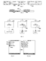
- FIG. 4 shows an example of a network of a multiple PSM system 400.
- the multiple PSM system 400 includes a first PSM 404, a second PSM 408, and a third PSM 412.
- the first PSM 404 has a serial number 5555666, and is coupled to a configuration tool 416.
- the second PSM 408 has a serial number AABBCCDD, and is coupled to a button-input IOM device 420 with a second PSM memory 428.
- the third PSM 412 has a serial number 12341234 and is coupled to a horn-output IOM device 424 with a third PSM memory 432.
- the multiple PSM system 400 allows mapping of an input device coupled to one PSM onto an output device coupled to another PSM. Therefore, for instance, the input instance of the button-input IOM device 420 can map its output instance onto the horn-output device 424 with the configuration tool 416. Once mapped using the tool 416, the button 420 can activate the
- the multiple PSM system 400 may include other input output devices coupled to the PSMs 404, 408, and 412.
- the user can use the configuration tool 416 coupled to the first PSM 404 to send out a remote mapping request 500 (as shown in FIG. 5) to perform the mapping of devices 420 and 424.
- the remote mapping request 500 includes an address 01h stored in a destination address segment ("Dest. Addr.") 504 and a serial number AABBCCDDh stored in a serial number segment ("PSM S/N”) 508.
- the second PSM 408 Upon reception of the request 500, the second PSM 408 will verify in its memory 428 if input instance 01 exists, and that the instance 01 has not already been mapped to the third PSM 412.
- the second PSM 408 then sends a mapping request command to the third PSM 412.
- the third PSM 412 Upon reception of the mapping request command, the third PSM 412 will try to find an available input instance in the memory 432. If an input instance is available in the memory 432, the third PSM 412 will transmit a result identifying the available input instance in the memory 432 to the second PSM 408.
- the second PSM 408 Upon reception of the availability, the second PSM 408 will send a remote request result back to the first PSM 404 to confirm the mapping has been completed. The user is now able to control the horn 424 with the button 420.
- the inputs and outputs of the system 100 including the PSM 112, the IOM 120, and the devices 108, 110 are defined by a programmable Boolean logic.
- the Boolean logic can be remotely configured using the configuration tool 132.
- the Boolean logic includes a set of function blocks, timers and logical operators. Outputs are managed according to the programmed logic and a plurality of I/O states in the system 100. However, if additional operations are preferred, the user has the option of programming the operations into the IOM 120 via the configuration tools.
- the programmable logic is primarily output driven. Each system output has an associated programmable logic.
- the programmable logic represents a combination of conditions, system inputs, and some function blocks. These conditions are described using the Backus-Naur Form (BNF). However, other semantic representations such as ALPHA, block structure language, FORMAC, IITRAN, LPL and PL/1 can also be used.
- BNF Backus-Naur Form
- Input values of the programmable Boolean logic are usually associated with hardware status, a button, or a sensor, for example. However, it is also possible to include other input values in the programmable logic such as input instances or contents of the addressing associated with the inputs. For example, input instances can be used as logic indicators. In other words, input instances can also be used as part of the determining Boolean logic parameters.
- Two types of action can generally be performed on the output of each device 108, 110: "set” and “clear.”
- Each of the two actions corresponds to some function of the device. For example, when a set action is invoked, a particular lock may be locked. As another example, a particular lock may be unlocked when a clear action invoked.
- These actions are normally locally executed, meaning that the targeted outputs are built in the device 108, 110.
- a "set” output energises an output while a "clear” output de-energises an output.
- FIG. 6 shows an example of Boolean logic 600 involving two inputs and one output.
- a door lock module IOM is responsible for the unlocking action.
- the door lock module receives at its input a Boolean logic representing the button devices.
- the door lock module IOM executes the unlocking Boolean logic 600.
- the unlocking Boolean logic 600 includes a condition segment 604, and a local action segment 608.
- the door lock module IOM will perform a device specific action -- i.e., unlocking the door. It will be appreciated that some devices need more complex conditions to trigger actions.
- the conditions might be based on a combination of time, a plurality of input states, and outputs states. For example, a system may need to energise door A starting when both input B and input C are "ON" for more than 5 seconds. The condition in this example verifies the simultaneous existence of two inputs for a particular duration.
- the programming of the system 100 can generally be performed using a plurality of user interfaces such as a desktop computer, a laptop computer, a palmtop computer, a handheld device, a pocket computer or the like.
- a user interface 700 displaying a main menu 720 on the configuration tool 132 (of FIG. 1) is shown in FIG. 7.
- the icons or options include a hardware setup icon 724, a tests and troubleshooting icon 728, a system tasks and preferences icon 732, an advanced hardware setup icon 736, and a zone management icon 740.
- Each icon guides the user through a specific programming process.
- the hardware setup icon 724 once tabbed or selected, allows a user to create or edit a device setup with a guided process as detailed hereinafter. Other selection methods including entering a return key can also be used.
- FIG. 7A After the guided process has entered a hardware setup display 744 as shown in FIG. 7A, the user will be presented with a new hardware setup option 748 and an edit hardware setup option 750.
- the configuration tool 132 may provide options for the user to select unlocking modules. For example, the key switch 764 and the button lock 766 can be used as the unlocking modules. That is, the door will be unlocked when an authorized user activates these devices. After the locking hardware has been selected, the configuration tool 132 will also prompt for door status via a door status hardware screen as shown in FIG. 7F.
- the door status hardware monitors whether a door is in an open position or in a closed position, or whether a locking device is locked or unlocked. The user then has the options to select a hardware item with a visual indicator to display the status of the door, or to finish the standard hardware setup by tabbing or selecting a finish icon 768. It should be noted the visual indicator will be able to display whether the door is physically closed, open, locked, unlocked, or in any other state.
- the main menu 720 also offers other options as described earlier.
- the tests and troubleshooting option 728 allows the user to view and test the hardware devices associated with an opening, or to view and test the hardware devices associated with a zone or a network of devices, among other things.
- An example of a display 800 of the tests and troubleshooting option 728 is shown in FIG. 8.
- the display 800 lists a total of three options, namely, a view opening option 802, a view zone option 804, and a view audit log option 806.
- the view zone option 804 allows the user to view and test all the hardware devices available on the network or the zone.
- the system may have a horn 810, a magnetic lock 812, an exit device 814, a key switch with lights 816 and a push button 818 available. The user is then allowed to test the inputs to and the output of these devices.
- the main menu 720 also includes the system task and preferences option 732 that allows the user to change a network password, to delete a device, and to upgrade the network, among other things.
- the zone management option 740 allows the user to add a device to a system, to create a new system, and to rename the system, for example.
- the user is also to program the system via the configuration tool 132 to set off an alarm, for example, using the advanced hardware setup option 736.
Landscapes
- Engineering & Computer Science (AREA)
- Power Engineering (AREA)
- Computer Networks & Wireless Communication (AREA)
- Signal Processing (AREA)
- Programmable Controllers (AREA)
- Alarm Systems (AREA)
- Cable Transmission Systems, Equalization Of Radio And Reduction Of Echo (AREA)
- Small-Scale Networks (AREA)
- Remote Monitoring And Control Of Power-Distribution Networks (AREA)
Abstract
Description
Claims (18)
- An electronic security system (100) comprising:a plurality of electronic security devices (108), each including an input/output module (120), which receives and decodes electronic signals and governs the functionality of the electronic security device; anda power supply (104), which sends electrical power to the plurality of electronic security devices (108) over power lines (116), the power supply including a power supply module (112), which contains a program dictating the functionality of the system, the power supply module sending signals to and receiving signals from the input/output modules over the power lines.
- An electronic security system (100) comprising:a power supply (104) having exactly two power supply terminals;a plurality of electronic security devices (108), each having exactly two security device terminals;a first wire (116) coupling together one of the terminals of the power supply and one of the terminals of each of the plurality of electronic security devices; anda second wire (116) coupling together the other of the terminals of the power supply (104) and the other of the terminals of each of the plurality of electronic security devices (108).
- The system of claim 1 or 2, further comprising a programming tool (132) connectable to and disconnectable from the power supply module (112) or the power lines to communicate information from the programming tool to the power supply module.
- The system of claim 3, wherein the programming tool (132) is a hand-held device.
- The system of claim 3 or 4, wherein the communicated information comprises at least one of a program and a command.
- The system of claim 3, 4 or 5, wherein the programming tool (132)' further comprises an access screen configured to access and control the electronic security devices.
- The system of any of the preceding claims, wherein the power supply includes a communication port allowing the power supply to be connected to an external peripheral device.
- The system of any one of the preceding claims, wherein the external peripheral device includes one of a computer, a printer and a monitor.
- The system of any one of claims 3 to 8 as appendant to claim 1 or 2, respectively, wherein the power supply module (112) of claim 1 includes a multiple power supply module interface allowing the power supply module to be connected to and communicate with power supply modules of other electronic security systems, or the power supply of claim 2 includes a multiple power supply interface allowing the power supply to be connected to and communicate with power supplies of other electronic security systems.
- The system of claim 1 or 2, further comprising a programming tool configured to communicate with the power supply module wirelessly.
- A method of establishing an electronic security system (100) comprising the steps of:establishing a power supply having a power supply module (112);electrically connecting exactly two terminals of a first electronic security device (108) to the power supply;electrically connecting exactly two terminals of a second electronic security device to the power supply; anduploading a program onto the power supply module to configure the functionality of the first and second electronic security devices.
- A method of establishing a programmable electronic security system (100) comprising the steps of:electrically connecting a configuration tool (132) to an electronic security device (108) of a first programmable electronic security system and downloading a functionality program from the first programmable electronic security system onto the configuration tool;disconnecting the configuration tool (132) from the electronic security device (108); anduploading the first programmable electronic security system functionality program from the configuration tool onto a second programmable electronic security system.
- The method of claim 11 or 12, wherein uploading the program onto the power supply module comprises electrically connecting a computer to the power supply module.
- The method of claim 13, wherein the computer is a hand-held computer.
- The method of claim 14, wherein the hand-held computer comprises a personal digital assistant, a palmtop computer or a pocket personal computer ("PC").
- The method of claim 11, wherein uploading the program onto the power supply module ("PSM") comprises wirelessly communicating the program to the PSM.
- The method of claim 13 as appendant to claim 11, wherein the power supply module (112) includes a multiple power supply module interface allowing the power supply module to be connected to and communicate with power supply modules of other electronic security systems.
- The method of claim 11 or 12, further comprising controlling at least one of the first and the second security devices with a programming tool (132).
Applications Claiming Priority (2)
| Application Number | Priority Date | Filing Date | Title |
|---|---|---|---|
| US850276 | 2004-05-20 | ||
| US10/850,276 US7616090B2 (en) | 2004-05-20 | 2004-05-20 | Electronic security system |
Publications (2)
| Publication Number | Publication Date |
|---|---|
| EP1598949A2 true EP1598949A2 (en) | 2005-11-23 |
| EP1598949A3 EP1598949A3 (en) | 2005-12-28 |
Family
ID=34941334
Family Applications (1)
| Application Number | Title | Priority Date | Filing Date |
|---|---|---|---|
| EP05253011A Withdrawn EP1598949A3 (en) | 2004-05-20 | 2005-05-17 | Electronic security system |
Country Status (3)
| Country | Link |
|---|---|
| US (1) | US7616090B2 (en) |
| EP (1) | EP1598949A3 (en) |
| JP (1) | JP2005332406A (en) |
Cited By (2)
| Publication number | Priority date | Publication date | Assignee | Title |
|---|---|---|---|---|
| WO2011020817A1 (en) * | 2009-08-20 | 2011-02-24 | Siemens Aktiengesellschaft | Intelligent actuator |
| US9363863B2 (en) | 2014-06-12 | 2016-06-07 | Biozone Scientific International, Inc. | Electromagnetic radiation emitter identification apparatus and associated methods |
Families Citing this family (29)
| Publication number | Priority date | Publication date | Assignee | Title |
|---|---|---|---|---|
| US7482923B2 (en) | 2005-01-27 | 2009-01-27 | The Chamberlain Group, Inc. | Alarm system interaction with a movable barrier operator method and apparatus |
| US20070103277A1 (en) * | 2005-11-09 | 2007-05-10 | Honeywell International, Inc. | Security system enhancement device key |
| US20080061926A1 (en) * | 2006-07-31 | 2008-03-13 | The Chamberlain Group, Inc. | Method and apparatus for utilizing a transmitter having a range limitation to control a movable barrier operator |
| US8643465B2 (en) * | 2006-12-04 | 2014-02-04 | The Chamberlain Group, Inc. | Network ID activated transmitter |
| US9698997B2 (en) | 2011-12-13 | 2017-07-04 | The Chamberlain Group, Inc. | Apparatus and method pertaining to the communication of information regarding appliances that utilize differing communications protocol |
| US9437967B2 (en) | 2011-12-30 | 2016-09-06 | Bedrock Automation Platforms, Inc. | Electromagnetic connector for an industrial control system |
| US12061685B2 (en) | 2011-12-30 | 2024-08-13 | Analog Devices, Inc. | Image capture devices for a secure industrial control system |
| US9727511B2 (en) | 2011-12-30 | 2017-08-08 | Bedrock Automation Platforms Inc. | Input/output module with multi-channel switching capability |
| US11144630B2 (en) | 2011-12-30 | 2021-10-12 | Bedrock Automation Platforms Inc. | Image capture devices for a secure industrial control system |
| US8862802B2 (en) * | 2011-12-30 | 2014-10-14 | Bedrock Automation Platforms Inc. | Switch fabric having a serial communications interface and a parallel communications interface |
| US11967839B2 (en) | 2011-12-30 | 2024-04-23 | Analog Devices, Inc. | Electromagnetic connector for an industrial control system |
| US11314854B2 (en) | 2011-12-30 | 2022-04-26 | Bedrock Automation Platforms Inc. | Image capture devices for a secure industrial control system |
| US9467297B2 (en) | 2013-08-06 | 2016-10-11 | Bedrock Automation Platforms Inc. | Industrial control system redundant communications/control modules authentication |
| US9191203B2 (en) | 2013-08-06 | 2015-11-17 | Bedrock Automation Platforms Inc. | Secure industrial control system |
| US8868813B2 (en) | 2011-12-30 | 2014-10-21 | Bedrock Automation Platforms Inc. | Communications control system with a serial communications interface and a parallel communications interface |
| US9600434B1 (en) | 2011-12-30 | 2017-03-21 | Bedrock Automation Platforms, Inc. | Switch fabric having a serial communications interface and a parallel communications interface |
| US10834094B2 (en) | 2013-08-06 | 2020-11-10 | Bedrock Automation Platforms Inc. | Operator action authentication in an industrial control system |
| US8971072B2 (en) | 2011-12-30 | 2015-03-03 | Bedrock Automation Platforms Inc. | Electromagnetic connector for an industrial control system |
| US10834820B2 (en) | 2013-08-06 | 2020-11-10 | Bedrock Automation Platforms Inc. | Industrial control system cable |
| US9122254B2 (en) | 2012-11-08 | 2015-09-01 | The Chamberlain Group, Inc. | Barrier operator feature enhancement |
| US9396598B2 (en) | 2014-10-28 | 2016-07-19 | The Chamberlain Group, Inc. | Remote guest access to a secured premises |
| US10229548B2 (en) | 2013-03-15 | 2019-03-12 | The Chamberlain Group, Inc. | Remote guest access to a secured premises |
| US9367978B2 (en) | 2013-03-15 | 2016-06-14 | The Chamberlain Group, Inc. | Control device access method and apparatus |
| US10613567B2 (en) | 2013-08-06 | 2020-04-07 | Bedrock Automation Platforms Inc. | Secure power supply for an industrial control system |
| CN105281061A (en) | 2014-07-07 | 2016-01-27 | 基岩自动化平台公司 | Industrial control system cable |
| US10305895B2 (en) | 2015-04-14 | 2019-05-28 | Blubox Security, Inc. | Multi-factor and multi-mode biometric physical access control device |
| CN104849631B (en) * | 2015-05-18 | 2017-10-17 | 湖南工业大学 | A kind of locomotive roof insulation testing system |
| US10554758B2 (en) | 2015-06-15 | 2020-02-04 | Blub0X Security, Inc. | Web-cloud hosted unified physical security system |
| US11459798B2 (en) | 2017-02-24 | 2022-10-04 | Schlage Lock Company Llc | Exit device systems and methods |
Family Cites Families (18)
| Publication number | Priority date | Publication date | Assignee | Title |
|---|---|---|---|---|
| US3978468A (en) * | 1974-11-11 | 1976-08-31 | Robert F. Moore | Intercom call signaling mechanism |
| US4367455A (en) * | 1981-02-12 | 1983-01-04 | Morton Fried | Powersaving room security system |
| US4755021A (en) * | 1982-08-02 | 1988-07-05 | Andrew Corporation | Self-aligning optical fiber directional coupler and fiber-ring optical rotation sensor using same |
| US4563625A (en) * | 1984-05-17 | 1986-01-07 | The Stanley Works | Automatic door control system |
| CA1260100A (en) | 1985-06-13 | 1989-09-26 | Donald E. Pezzolo | Security control system |
| US4744021A (en) | 1986-02-01 | 1988-05-10 | Kristy Brickton D | Computer controlled deadbolts |
| US4912461A (en) * | 1986-11-05 | 1990-03-27 | Cellular Control Systems Corporation | Apparatus and network for transferring packets of electronic signals and associated method |
| JPS63143698A (en) * | 1986-12-08 | 1988-06-15 | アツミ電氣株式会社 | Alarm |
| US4845490A (en) * | 1987-01-28 | 1989-07-04 | Emhart Industries, Inc. | Electronic locking system |
| EP0359178B1 (en) * | 1988-09-14 | 1995-12-13 | Mitsubishi Denki Kabushiki Kaisha | Load control system |
| US5070442A (en) * | 1989-12-14 | 1991-12-03 | Syron Townson Ann T | Computerized door locking and monitoring system using power-line carrier components |
| DE4134922C1 (en) * | 1991-10-23 | 1992-12-03 | Anatoli 3013 Barsinghausen De Stobbe | |
| JPH07263935A (en) * | 1994-03-24 | 1995-10-13 | Hochiki Corp | Antenna device |
| JPH10502181A (en) * | 1994-06-20 | 1998-02-24 | ネオマジック・コーポレイション | Graphics controller integrated circuit without memory interface |
| US5777545A (en) * | 1995-05-09 | 1998-07-07 | Elcom Technologies Corporation | Remote control apparatus for power line communications system |
| US5838226A (en) * | 1996-02-07 | 1998-11-17 | Lutron Electronics Co.Inc. | Communication protocol for transmission system for controlling and determining the status of electrical devices from remote locations |
| AU784517B2 (en) * | 1999-11-15 | 2006-04-27 | Ge Security, Inc. | Highly reliable power line communications system |
| US7091830B2 (en) * | 2001-09-04 | 2006-08-15 | Technical Development Consultants, Inc. | Subterranean two-wire power and communications network |
-
2004
- 2004-05-20 US US10/850,276 patent/US7616090B2/en active Active
-
2005
- 2005-05-17 EP EP05253011A patent/EP1598949A3/en not_active Withdrawn
- 2005-05-20 JP JP2005147425A patent/JP2005332406A/en active Pending
Cited By (2)
| Publication number | Priority date | Publication date | Assignee | Title |
|---|---|---|---|---|
| WO2011020817A1 (en) * | 2009-08-20 | 2011-02-24 | Siemens Aktiengesellschaft | Intelligent actuator |
| US9363863B2 (en) | 2014-06-12 | 2016-06-07 | Biozone Scientific International, Inc. | Electromagnetic radiation emitter identification apparatus and associated methods |
Also Published As
| Publication number | Publication date |
|---|---|
| US7616090B2 (en) | 2009-11-10 |
| EP1598949A3 (en) | 2005-12-28 |
| JP2005332406A (en) | 2005-12-02 |
| US20050258933A1 (en) | 2005-11-24 |
Similar Documents
| Publication | Publication Date | Title |
|---|---|---|
| US7616090B2 (en) | Electronic security system | |
| US8230083B2 (en) | Communication adapter apparatus, communication adapter, method of writing data in nonvolatile memory, and electric apparatus and ROM writer used for the method | |
| US6269288B1 (en) | Smart switch | |
| CN102782595B (en) | control cabinet monitoring device | |
| CN101163039B (en) | Apparatus for restoring network information for home network system and method thereof | |
| JP2019192244A (en) | Safety switch | |
| US20070255969A1 (en) | Device for Controlling the Energy Flow Between an Energy Supply Network and an Electric Device Connected Thereto | |
| US8086357B2 (en) | Offline configuration using USB download in an integrated power distribution system | |
| JP4162236B2 (en) | Heat source machine communication system | |
| JP3438685B2 (en) | Communication terminal device | |
| WO2002054163A1 (en) | Control arrangement based on can-bus technology | |
| JP2004030930A (en) | Table tap with communication and power control function | |
| JP7775983B2 (en) | Network unit, power supply, and maintenance system | |
| CN1708953B (en) | Communication adapter device | |
| JP2025074861A (en) | Contact monitoring unit and remote contact monitoring system | |
| JPH01295597A (en) | Electronic equipment controller | |
| Ajenikoko et al. | A Microcontroller Framework for PC Based Electrical Appliance Control System | |
| HK1114972B (en) | Communication adapter | |
| HK1082350B (en) | Communication adapter device | |
| CA2324750A1 (en) | Device for uniform selection of terminals | |
| WO2009055497A1 (en) | Residential environmental management control system interlink | |
| CA2703213A1 (en) | Residential environmental management control system interlink |
Legal Events
| Date | Code | Title | Description |
|---|---|---|---|
| PUAI | Public reference made under article 153(3) epc to a published international application that has entered the european phase |
Free format text: ORIGINAL CODE: 0009012 |
|
| PUAL | Search report despatched |
Free format text: ORIGINAL CODE: 0009013 |
|
| AK | Designated contracting states |
Kind code of ref document: A2 Designated state(s): AT BE BG CH CY CZ DE DK EE ES FI FR GB GR HU IE IS IT LI LT LU MC NL PL PT RO SE SI SK TR |
|
| AX | Request for extension of the european patent |
Extension state: AL BA HR LV MK YU |
|
| RIC1 | Information provided on ipc code assigned before grant |
Ipc: 7G 08B 25/04 B Ipc: 7G 08B 25/06 B Ipc: 7H 04B 3/54 A |
|
| AK | Designated contracting states |
Kind code of ref document: A3 Designated state(s): AT BE BG CH CY CZ DE DK EE ES FI FR GB GR HU IE IS IT LI LT LU MC NL PL PT RO SE SI SK TR |
|
| AX | Request for extension of the european patent |
Extension state: AL BA HR LV MK YU |
|
| AKX | Designation fees paid | ||
| REG | Reference to a national code |
Ref country code: DE Ref legal event code: 8566 |
|
| STAA | Information on the status of an ep patent application or granted ep patent |
Free format text: STATUS: THE APPLICATION IS DEEMED TO BE WITHDRAWN |
|
| 18D | Application deemed to be withdrawn |
Effective date: 20060629 |