EP1598915A1 - Electronic apparatus - Google Patents
Electronic apparatus Download PDFInfo
- Publication number
- EP1598915A1 EP1598915A1 EP05009237A EP05009237A EP1598915A1 EP 1598915 A1 EP1598915 A1 EP 1598915A1 EP 05009237 A EP05009237 A EP 05009237A EP 05009237 A EP05009237 A EP 05009237A EP 1598915 A1 EP1598915 A1 EP 1598915A1
- Authority
- EP
- European Patent Office
- Prior art keywords
- connector
- battery
- indication
- opening
- housing part
- Prior art date
- Legal status (The legal status is an assumption and is not a legal conclusion. Google has not performed a legal analysis and makes no representation as to the accuracy of the status listed.)
- Granted
Links
Images


Classifications
-
- H—ELECTRICITY
- H02—GENERATION; CONVERSION OR DISTRIBUTION OF ELECTRIC POWER
- H02J—ELECTRIC POWER NETWORKS; CIRCUIT ARRANGEMENTS OR SYSTEMS FOR SUPPLYING OR DISTRIBUTING ELECTRIC POWER; SYSTEMS FOR STORING ELECTRIC ENERGY
- H02J7/00—Circuit arrangements for charging or discharging batteries or for supplying loads from batteries
- H02J7/70—Circuit arrangements for charging or discharging batteries or for supplying loads from batteries characterised by the mechanical construction
- H02J7/751—Circuit arrangements for charging or discharging batteries or for supplying loads from batteries characterised by the mechanical construction concerning the insertion or the connection of the batteries
Definitions
- the present invention relates to an electronic apparatus using a battery as a power source connected thereto through a connecting cable and more particularly to an electronic apparatus provided with a guiding indication which informs a user of a manner of mounting the battery in the electronic apparatus.
- a dry battery, an AC adaptor, a charging battery, and the like are commonly used as a driving source.
- the apparatuses include an electronic apparatus using only a single type of them as the driving source and another apparatus selectively using one of several types as the driving source according to a using condition.
- a label producing machine which produces a label by printing thereon inputted contents such as characters, symbols, etc. is internally provided with a charging battery.
- the machine is placed on a charger stand during non-use to charge the charging battery, and is removed from the charging stand before use and uses electricity stored in the charging battery.
- Some label producing machines are not provided with a charging battery in a body of each machine at the time of purchase.
- a user has to insert the charging battery in a battery compartment while paying attention to orientation or positioning of the charging battery and then connect a connector provided at an end of a cable extending from the charging battery to a connector provided inside the battery compartment.
- This connection of the connectors is usually conducted by engagement of the connectors with each other.
- the connectors often have structures which cannot be connected unless connecting conditions such as positional relation between the connectors, an orientation of each connector to be connected, and others are properly satisfied.
- a guiding indication which indicates how to properly connect the connectors is additionally applied to near the connector provided in the battery compartment.
- a label producing machine (Product name: PT-18R manufactured by Brother Kogyo Kabushiki Kaisha) is provided with such guiding indication on a surface of a stepped part formed in the battery compartment, the surface being higher and in parallel with a bottom surface of the battery compartment.
- the guiding indication is integrally formed with a member or material forming the battery compartment at the time of molding.
- Another label producing machine (Product name: PT-55 manufactured by Brother Kogyo Kabushiki Kaisha) is structured to work on four dry batteries.
- a guiding indication which indicates an orientation of the dry batteries to be inserted is provided near an opening of the battery compartment. This guiding indication is also formed integrally with a member or material forming the opening at the time of molding.
- a washable electronic apparatus such as an electric razor or the like is arranged so that a power supply part such as a battery is removably connected to a body through a power supply plug, thereby supplying electric power to the body. If the power supply plug is connected to the body while a detachable part of the power supply plug is wetted, electric current is caused to flow through between electrode terminals in the detachable part, thus corroding the electrode terminals.
- Japanese patent application laid-open No. 2001-244013 discloses that a partition wall is provided for preventing electrical conduction between electrode terminals which may be caused by water.
- Fig. 5 of Document 1 shows a power supply plug having right and left electrode terminals and a cover which covers them.
- FIGs. 1 and 2 of Document 1 show an electrical appliance provided at a bottom with a detachable part to which the power supply plug is connected.
- the electrical appliance and the power supply plug are constructed to be connectable only when respective detachable parts are aligned in face to face at a predetermined angle and be unconnectable if they are turned about an axis from the aligned position by e.g. 180°.
- the guiding indication is provided inside the battery compartment which receives the charging battery, so that it is inconspicuous to a user. Even if the user can recognize the existence of the guiding indication, it is illegible because it is apt to be hidden behind the machine body. When the charging battery is housed in the battery compartment, the indication would become further illegible. During works to connect the connectors, furthermore, the guiding indication would be hidden behind the user's hand, the cable extending from the charging battery held by his hand, and the connector provided at the end of the cable. This makes it difficult for the user to correctly connect the connectors.
- the power supply plug is applied with the indications representing the polarity of each terminal, whereas the body of the electrical appliance is not applied with any indication. Consequently, the user may not correctly connect the plug to the electrical appliance with correct polarities by one connecting work.
- the present invention has been made in view of the above circumstances and has an object to overcome the above problems and to provide an electronic apparatus provided with a guiding indication which indicates a connecting orientation of a battery-side connector in a conspicuous position and in a easy-to-understand form, so that a battery and an apparatus body can be connected smoothly through connectors without fails.
- an electronic apparatus comprising: an apparatus body; a battery which supplies power to the apparatus; a housing part formed in the body in which the battery is housed; an opening through which the battery is inserted in the housing part; a connecting cable; a first connector connected to the battery through the connecting cable; a second connector which is provided in the body and electrically connects the battery to the body when the first connector is connected to the second connector, the first connector being detachably connected to the second connector; and a connector-connection indication which is provided on an outer surface of the body near the opening and the second connector and is arranged to indicate a connecting orientation of the first connector.
- the battery-side connector connected to the battery through the connecting cable and the body-side connector for electrically connecting the battery housed in the housing part to the body are detachably connected.
- the connector-connection indication which indicates a connecting orientation of the battery-side connector is provided on a surface near the opening of the housing part and also near the body-side connector. This indication is easy to view and will not be hidden behind the body of the electronic apparatus. Further, the indication is legible even after the battery is inserted in the housing part. During connection of the connectors, the indication will not be hidden behind by the user's hand, the cable extending from the battery held by his hand, and the connector provided at the end of the cable. Accordingly, it is possible to prevent failures of connection between the connectors.
- an electronic apparatus comprising: an apparatus body; a battery which supplies power to the apparatus; a housing part formed in the body in which the battery is housed; an opening through which the battery is inserted in the housing part; a connecting cable; a first connector connected to the battery through the connecting cable; a second connector which is provided in the body and electrically connects the battery to the body when the first connector is connected to the second connector, the first connector being detachably connected to the second connector; a connector-connection indication which is provided on an outer surface of the body near the opening and the second connector and is arranged to indicate a connecting orientation of the first connector; and a battery-housing indication which is provided on the surface near the opening and adjacent to the connector-connection indication and which represents a shape and a housing orientation of the battery to be housed in the housing part.
- the connector-connection indication is easy to view and will not be hidden behind the body of the electronic apparatus. Further, the indication is legible even after the battery is inserted in the housing part. During connection of the connectors, the indication will not be hidden behind by the user's hand, the cable extending from the battery held by his hand, and the connector provided at the end of the cable. Accordingly, it is possible to prevent failures of connection between the connectors. Further, when the opening of the housing part is closed by the cover, covering over the battery housed in the housing part, the user can recognize that the battery has been housed inside, which is convenient. It is therefore possible to give the user to clearly understand the type of connector as compared with the case where only the connector-connection indication is provided.
- the apparatus also can have a simple appearance. Indication of the housing orientation of the battery to be housed allows the user to house the battery in the housing part correctly.
- an electronic apparatus comprising: an apparatus body; a battery which supplies power to the apparatus; a housing part formed in the body in which the battery is housed; an opening through which the battery is inserted in the housing part; a connecting cable; a first connector connected to the battery through the connecting cable; a second connector which is provided in the body and electrically connects the battery to the body when the first connector is connected to the second connector, the first connector being detachably connected to the second connector; a cover which is removably attached to the body to open and close the opening, thereby covering the battery housed in the housing part; a connector-connection indication which is provided on an outer surface of the body near the opening and the second connector and is arranged to indicate a connecting orientation of the first connector by indicating electric polarities of a plurality of terminals constituting the first connector in different colors, showing a difference in electric polarities by color-coding; and a battery-housing indication which is provided on the surface near the opening and adjacent to the connector-
- the connector-connection indication is easy to view and will not be hidden behind the body of the electronic apparatus. Further, the indication is legible even after the battery is inserted in the housing part. During connection of the connectors, the indication will not be hidden behind by the user's hand, the cable extending from the battery held by his hand, and the connector provided at the end of the cable. Accordingly, it is possible to prevent failures of connection between the connectors. Further, while the opening of the housing part is covered by the cover, covering over the battery housed in the housing part, the user can recognize that the battery has been housed inside, which is convenient. It is therefore possible to give the user to clearly understand the type of connector as compared with the case where only the connector-connection indication is provided. Thus, the apparatus can have a simple appearance. Indication of the housing orientation of the battery to be housed allows the user to house the battery in the housing part correctly.
- the cover since the battery which is less often replaced normally is covered by the cover, it is inconspicuous to the user. In the case where some components except the battery need be replaced, the cover is effective in making the user divert attention from the battery.
- the apparatus can be simple in design.
- the battery itself and the connecting cable associated with the battery are indicated. Thus, the user can recognize the orientation of the battery and more surely house the battery in the housing part.
- the indicated color allows the user to recognize the polarity of each terminal and correspondingly connect the battery-side connector to the body-side connector in a correct manner.
- the color of the connector-connection indication singly allows the user to correctly connect the battery-side connector to the body-side connector.
- the character or symbol forming the indication allows the user who reads it to recognize a difference in polarity so that the user can more correctly connect the battery-side connector to the body-side connector as compared with the case where he gives attention to only the color.
- Such structure can have effect on a person who has defective color vision.
- At least one of the connector-connection indication and the battery-housing indication is provided as an adhesive label, which can achieve a reduction in cost.
- an electronic apparatus comprising: an apparatus body; a battery which supplies power to the apparatus; a housing part formed in the body in which the battery is housed; an opening through which the battery is inserted in the housing part; a connecting cable; a first connector connected to the battery through the connecting cable; a second connector which is provided in the body and electrically connects the battery to the body when the first connector is connected to the second connector, the first connector being detachably connected to the second connector; a cover which is removably attached to the body to open and close the opening, thereby covering the battery housed in the housing part; a connector-connection indication which is provided on an outer surface of the body near the opening and the second connector and is arranged to indicate a connecting orientation of the first connector by indicating electric polarities of a plurality of terminals constituting the first connector in different colors, showing a difference in electric polarities by color-coding; and a battery-housing indication which is provided on the surface near the opening and adjacent to the connector-
- the connector-connection indication is easy to view and will not be hidden behind the body of the electronic apparatus. Further, the indication is legible even after the battery is inserted in the housing part. During connection of the connectors, the indication will not be hidden behind by the user's hand, the cable extending from the battery held by his hand, and the connector provided at the end of the cable. Accordingly, it is possible to prevent failures of connection between the connectors. Further, while the opening of the housing part is covered by the cover, covering over the battery housed in the housing part, the user can recognize that the battery has been housed inside, which is convenient. It is therefore possible to give the user to clearly understand the type of connector as compared with the case where only the connector-connection indication is provided. Thus, the apparatus can have a simple appearance. Indication of the housing orientation of the battery to be housed allows the user to house the battery in the housing part correctly.
- the cover since the battery which is less often replaced normally is covered by the cover, it is inconspicuous to the user. In the case where some components except the battery need be replaced, the cover is effective in making the user divert attention from the battery.
- the apparatus can be simple in design.
- the indicated color allows the user to recognize the polarity of each terminal and correspondingly connect the battery-side connector to the body-side connector in a correct manner.
- the color of the connector-connection indication singly allows the user to correctly connect the battery-side connector to the body-side connector.
- the character or symbol forming the indication allows the user who reads it to recognize a difference in polarity so that the user can more correctly connect the battery-side connector to the body-side connector as compared with the case where he gives attention to only the color.
- Such structure can have effect on a person who has defective color vision.
- At least one of the connector-connection indication and the battery-housing indication is provided as an adhesive label, which can achieve a reduction in cost.
- a tape printer 3 in the present embodiment is principally constructed of a body 9 containing various components or elements and a charging battery 40 detachably connected to the body 9 (see Fig. 5).
- a schematic structure of the tape printer 3 in the present embodiment will be described below, referring to Figs. 1 through 5.
- Fig. 1 is a plan view of the tape printer 3.
- character input keys 5 for inputting characters to form a text as document data
- print key 6 for instructing printing of the text
- space key 7 for converting katakana or hiragana to kanji (which are different character types used in Japan) and inputting a space
- return key 8 for instructing linefeed
- cursor key 11 for moving a cursor up and down, right and left on a liquid crystal display 10.
- a left side wall 13 of the tape printer 3 is formed with a tape discharge opening 14 through which a printed tape is discharged.
- a right side wall 17 of the tape printer 3 is formed with an adaptor insertion opening 18 in which a power supply adaptor is inserted, a connector 19 to which a USB cable is connected for connection to a personal computer not shown, and others.
- the tape printer 3 constructed as above is horizontally placed on a table or the like so that the top surface 4 faces upward and operates either on AC power through the power supply adaptor inserted in the adaptor insertion opening 18 or a built-in secondary battery without insertion of the power supply adaptor. Thus, the tape printing can be conducted.
- Fig. 2 is a bottom view of the tape printer 3 in the present embodiment. As shown in Fig. 2, the bottom of the tape printer 3 having a substantially box-like shape is entirely covered by an opening/closing lid 20.
- This lid 20 is attached to the body 9 of the printer 3 with hinges (not shown) provided at an upper left and lower left corners in the figure, respectively. The lid 20 is turned about the hinges in a direction perpendicular to a drawing paper into an opened state.
- Fig. 3 is a bottom view of the tape printer 3 with the lid 20 opened, showing the inside of the printer 3.
- the lid 20 in an opened state is omitted from the figure.
- the body 9 is formed with a battery compartment 48 (a housing part of the invention), which receives a charging battery 40 as shown in Fig. 4.
- a battery cover 31 is provided to close an opening 48a of the battery compartment 48, thus covering the charging battery 40.
- This battery cover 31 is removably attached to the body 9 (the details will be mentioned later).
- a cassette compartment 32 like a cavity is centrally formed in the tape printer 3.
- a print head 34 which is heated to form images on a tape used as a print medium is placed in the cassette compartment 32 at an inside back (an upper part in the figures).
- a platen roller 36 for feeding the tape is also placed at the back (above in the figures) of the cassette compartment 32 and facing the print head 34 through the tape.
- a phantom line 33 represents the contour of a cassette housed in the cassette compartment 32.
- a label 38 related to a charging battery is affixed on an outer surface of the body 9 near a lower part of the opening 48a. This label 38 corresponding to a connector-connection indication and a battery-housing indication of the present invention. The details of the label 38 will be mentioned later. As shown in Fig. 3, the label 38 can be seen clearly by a user even when the battery cover 31 is attached.
- Fig. 4 is another bottom view of the printer 3 with the battery cover 31 removed, showing the battery compartment 48 in which the charging battery 40 is housed.
- Extended from the charging battery 40 are two cords 42a and 42b serving as a connecting cable, which are connected to a battery-side connector 44 (a first connector of the invention).
- This connector 44 is detachably connected to a body-side connector 46 (a second connector of the invention) provided in a side wall forming the battery compartment 48 in the body 9.
- the cord 42a has positive (+) polarity and includes a surface made of an insulative flexible resin material colored in red.
- the cord 42b has negative (-) polarity and includes a surface made of the same material as that of the cord 42, but colored in black.
- the label 38 is affixed to the outer surface of the body 9 near the opening 48a, in particular, a closest portion to the body-side connector 46.
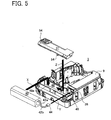
- Fig. 5 is a perspective view showing a manner of mounting the charging battery 40 in the tape printer 3.
- a right front side of the printer 3 corresponds to the user side and a left back of the printer 3 corresponds to the rear side.
- the charging battery 40 is not housed in the tape printer 3. Since the tape printer 3 does not operate unless the charging battery 40 is housed therein, the charging battery 40 has to be housed before use of the tape printer 3 in the following manner.
- the charging battery 40 is inserted in the battery compartment 48 as indicated by a broad arrow X in an orientation such that the cords 42a and 42b are on the user side of the tape printer 3.
- Fig. 6 is a plan view of the label 38, showing a configuration thereof.
- the label 38 is configured of a battery-housing indication 50 representing that the battery has been housed in the battery compartment 48 and a connector-connection indication 52 representing an orientation, or positioning, of the connector.
- the battery-housing indication 50 includes a battery mark 50a taking the shape of a dry battery and an arrow mark 50b, which show that a battery is placed in a position indicated by the arrow mark 50b. This makes it possible for a user to easily recognize the existence of the battery even when the battery cover 31 is put on the battery compartment 48.
- the connector-connection indication 52 includes a polarity mark 52a consisting of a white mark "+" on a red background and a polarity mark 52b consisting of a white mark "-" on a black background, which show the user the orientation of the battery-side connector 44 to be connected to the body-side connector 46. These marks 52a and 52b represent a difference in electric polarity.
- the indication 52 indicates that the connector 44 is correctly fit in the connector 46 when the cord 42a having positive polarity, coated with the red synthetic resin, and the cord 42b having negative polarity, coated with the black synthetic resin, are positioned in correspondence with the red polarity mark 52a and the black polarity mark 52b, respectively.
- the label 38 is affixed so that the battery-housing indication 50 is on the rear side and the connector-connection indication 52 is on the user side as shown in Fig. 4. Thus, the connector-connection indication 52 is positioned close to the body-side connector 46.
- the battery-side connector 44 is connected to the body-side connector 46 as indicated by a narrow arrow Y in accordance with the marks 52a and 52b of the connector-connection indication 52.
- the battery cover 31 is put on the opening 48a of the battery compartment 48 and in a position slightly closer to the user side, as shown by a broad arrow Z.
- the cover 31 is moved toward the rear side until it comes into contact with an inside back wall of the battery compartment 48. Accordingly, projections 54 formed one at each of a back end, and right and left sides of the cover 31 are brought in engagement with catching parts (not shown) formed in the opening 48a of the battery compartment 48. In this manner, the cover 31 is removably attached to the body 9.
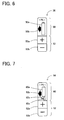
- FIG. 7 is a plan view of a charging battery label in another embodiment.
- a label 58 has an identical configuration to the label 38 mentioned above except for a battery-housing indication. The identical parts to those of the label 38 are indicated by the same numerals and their explanation is omitted.
- a mark representing a battery-housing indication 60 which is given in the form more resembling to an actual charging battery, includes a connecting cable mark 60b and a battery-side connector mark 60c in addition to a battery body mark 60a.
- the battery-housing indication and the connector-connection indication need not be configured as the single label 38 or 58.
- the indications may be provided as separate labels.
- the battery-housing indication and the connector-connection indication are both provided in the form of an adhesive label.
- these indications may be engraved on an inner surface of the electronic apparatus when it is molded by use of a metallic mold. In this case, the engraving position corresponds to the affixing position of the label mentioned above.
- one of the battery-housing indication and the connector-connection indication may be formed as an engraved mark by the metallic mold, and the other may be formed as an adhesive label.
- the connector-connection indication is preferably positioned close to the body-side connector in Fig. 4 as indicated in the above embodiment. However, it may be placed slightly out of a desired position.
- the battery-housing indication may especially be provided at a different position from the above described position.
- the battery-housing indication 50 is placed on the rear side of the printer 3 so that it is vertically adjacent to the connector-connection indication 52 in Figs. 6 and 7, for example, it may be at the left of the connector-connection indication 52.
- polarities may be represented as characters; "Plus” and “Minus” instead of using symbols; "+” and "-”.
- the connecting cable of the charging battery may be modified.
- the cord 42a remains colored in red and the cord 42b may be uncolored, remaining white.
- the battery-side connector 44 may be colored in red at a closer part to the cord 42a and in black at a closer part to the cord 42b.
- the battery-housing indication is not limited to the mark taking the form of a battery and may be constituted of characters representing a battery or a charging battery, or in combination of such characters and the mark.
Landscapes
- Engineering & Computer Science (AREA)
- Power Engineering (AREA)
- Battery Mounting, Suspending (AREA)
- Charge And Discharge Circuits For Batteries Or The Like (AREA)
Abstract
Description
- The present invention relates to an electronic apparatus using a battery as a power source connected thereto through a connecting cable and more particularly to an electronic apparatus provided with a guiding indication which informs a user of a manner of mounting the battery in the electronic apparatus.
- In conventional compact electronic apparatuses, a dry battery, an AC adaptor, a charging battery, and the like are commonly used as a driving source. The apparatuses include an electronic apparatus using only a single type of them as the driving source and another apparatus selectively using one of several types as the driving source according to a using condition.
- In one of the compact electronic apparatuses, for example, a label producing machine which produces a label by printing thereon inputted contents such as characters, symbols, etc. is internally provided with a charging battery. The machine is placed on a charger stand during non-use to charge the charging battery, and is removed from the charging stand before use and uses electricity stored in the charging battery.
- Some label producing machines are not provided with a charging battery in a body of each machine at the time of purchase. Thus, a user has to insert the charging battery in a battery compartment while paying attention to orientation or positioning of the charging battery and then connect a connector provided at an end of a cable extending from the charging battery to a connector provided inside the battery compartment. Even after mounting the charging battery once, the user has to replace it with new one if the mounted charging battery is weak or dead, though the number of replacement is low. This connection of the connectors is usually conducted by engagement of the connectors with each other. However, the connectors often have structures which cannot be connected unless connecting conditions such as positional relation between the connectors, an orientation of each connector to be connected, and others are properly satisfied. Accordingly, in many cases, a guiding indication which indicates how to properly connect the connectors is additionally applied to near the connector provided in the battery compartment. For instance, a label producing machine (Product name: PT-18R manufactured by Brother Kogyo Kabushiki Kaisha) is provided with such guiding indication on a surface of a stepped part formed in the battery compartment, the surface being higher and in parallel with a bottom surface of the battery compartment. The guiding indication is integrally formed with a member or material forming the battery compartment at the time of molding.
- Another label producing machine (Product name: PT-55 manufactured by Brother Kogyo Kabushiki Kaisha) is structured to work on four dry batteries. A guiding indication which indicates an orientation of the dry batteries to be inserted is provided near an opening of the battery compartment. This guiding indication is also formed integrally with a member or material forming the opening at the time of molding.
- A washable electronic apparatus such as an electric razor or the like is arranged so that a power supply part such as a battery is removably connected to a body through a power supply plug, thereby supplying electric power to the body. If the power supply plug is connected to the body while a detachable part of the power supply plug is wetted, electric current is caused to flow through between electrode terminals in the detachable part, thus corroding the electrode terminals. To prevent such electric corrosion, Japanese patent application laid-open No. 2001-244013 (hereinafter, Document 1) discloses that a partition wall is provided for preventing electrical conduction between electrode terminals which may be caused by water. Fig. 5 of
Document 1 shows a power supply plug having right and left electrode terminals and a cover which covers them. On a surface of the cover, marks representing respective polarities of the electrode terminals are applied. Figs. 1 and 2 ofDocument 1 show an electrical appliance provided at a bottom with a detachable part to which the power supply plug is connected. The electrical appliance and the power supply plug are constructed to be connectable only when respective detachable parts are aligned in face to face at a predetermined angle and be unconnectable if they are turned about an axis from the aligned position by e.g. 180°. - In the former label producing machine (PT-18R), however, the guiding indication is provided inside the battery compartment which receives the charging battery, so that it is inconspicuous to a user. Even if the user can recognize the existence of the guiding indication, it is illegible because it is apt to be hidden behind the machine body. When the charging battery is housed in the battery compartment, the indication would become further illegible. During works to connect the connectors, furthermore, the guiding indication would be hidden behind the user's hand, the cable extending from the charging battery held by his hand, and the connector provided at the end of the cable. This makes it difficult for the user to correctly connect the connectors.
- In the electrical appliance shown in
Document 1, the power supply plug is applied with the indications representing the polarity of each terminal, whereas the body of the electrical appliance is not applied with any indication. Consequently, the user may not correctly connect the plug to the electrical appliance with correct polarities by one connecting work. - The present invention has been made in view of the above circumstances and has an object to overcome the above problems and to provide an electronic apparatus provided with a guiding indication which indicates a connecting orientation of a battery-side connector in a conspicuous position and in a easy-to-understand form, so that a battery and an apparatus body can be connected smoothly through connectors without fails.
- Additional objects and advantages of the invention will be set forth in part in the description which follows and in part will be obvious from the description, or may be learned by practice of the invention. The objects and advantages of the invention may be realized and attained by means of the instrumentalities and combinations particularly pointed out in the appended claims.
- To achieve the purpose of the invention, there is provided an electronic apparatus comprising: an apparatus body; a battery which supplies power to the apparatus; a housing part formed in the body in which the battery is housed; an opening through which the battery is inserted in the housing part; a connecting cable; a first connector connected to the battery through the connecting cable; a second connector which is provided in the body and electrically connects the battery to the body when the first connector is connected to the second connector, the first connector being detachably connected to the second connector; and a connector-connection indication which is provided on an outer surface of the body near the opening and the second connector and is arranged to indicate a connecting orientation of the first connector.
- According to the above electronic apparatus, while the battery is housed in the housing part of the body, the battery-side connector connected to the battery through the connecting cable and the body-side connector for electrically connecting the battery housed in the housing part to the body are detachably connected. The connector-connection indication which indicates a connecting orientation of the battery-side connector is provided on a surface near the opening of the housing part and also near the body-side connector. This indication is easy to view and will not be hidden behind the body of the electronic apparatus. Further, the indication is legible even after the battery is inserted in the housing part. During connection of the connectors, the indication will not be hidden behind by the user's hand, the cable extending from the battery held by his hand, and the connector provided at the end of the cable. Accordingly, it is possible to prevent failures of connection between the connectors.
- According to another aspect of the invention, there is provided an electronic apparatus comprising: an apparatus body; a battery which supplies power to the apparatus; a housing part formed in the body in which the battery is housed; an opening through which the battery is inserted in the housing part; a connecting cable; a first connector connected to the battery through the connecting cable; a second connector which is provided in the body and electrically connects the battery to the body when the first connector is connected to the second connector, the first connector being detachably connected to the second connector; a connector-connection indication which is provided on an outer surface of the body near the opening and the second connector and is arranged to indicate a connecting orientation of the first connector; and a battery-housing indication which is provided on the surface near the opening and adjacent to the connector-connection indication and which represents a shape and a housing orientation of the battery to be housed in the housing part.
- According to the above electronic apparatus, the connector-connection indication is easy to view and will not be hidden behind the body of the electronic apparatus. Further, the indication is legible even after the battery is inserted in the housing part. During connection of the connectors, the indication will not be hidden behind by the user's hand, the cable extending from the battery held by his hand, and the connector provided at the end of the cable. Accordingly, it is possible to prevent failures of connection between the connectors. Further, when the opening of the housing part is closed by the cover, covering over the battery housed in the housing part, the user can recognize that the battery has been housed inside, which is convenient. It is therefore possible to give the user to clearly understand the type of connector as compared with the case where only the connector-connection indication is provided. The apparatus also can have a simple appearance. Indication of the housing orientation of the battery to be housed allows the user to house the battery in the housing part correctly.
- According to another aspect of the invention, there is provided an electronic apparatus comprising: an apparatus body; a battery which supplies power to the apparatus; a housing part formed in the body in which the battery is housed; an opening through which the battery is inserted in the housing part; a connecting cable; a first connector connected to the battery through the connecting cable; a second connector which is provided in the body and electrically connects the battery to the body when the first connector is connected to the second connector, the first connector being detachably connected to the second connector; a cover which is removably attached to the body to open and close the opening, thereby covering the battery housed in the housing part; a connector-connection indication which is provided on an outer surface of the body near the opening and the second connector and is arranged to indicate a connecting orientation of the first connector by indicating electric polarities of a plurality of terminals constituting the first connector in different colors, showing a difference in electric polarities by color-coding; and a battery-housing indication which is provided on the surface near the opening and adjacent to the connector-connection indication and which represents a shape and a housing orientation of the battery to be housed in the housing part, and a mark representing the connecting cable to be connected to the first connector; wherein the plurality of cords or a surface of the first connector corresponding to the plurality of cords are color-coded in similar colors to colors of the polarity marks based on the difference in electric polarity, and at least one of the connector-connection indication and the battery-housing indication is a label affixed on the surface near the opening and the second connector.
- According to the above electronic apparatus, the connector-connection indication is easy to view and will not be hidden behind the body of the electronic apparatus. Further, the indication is legible even after the battery is inserted in the housing part. During connection of the connectors, the indication will not be hidden behind by the user's hand, the cable extending from the battery held by his hand, and the connector provided at the end of the cable. Accordingly, it is possible to prevent failures of connection between the connectors. Further, while the opening of the housing part is covered by the cover, covering over the battery housed in the housing part, the user can recognize that the battery has been housed inside, which is convenient. It is therefore possible to give the user to clearly understand the type of connector as compared with the case where only the connector-connection indication is provided. Thus, the apparatus can have a simple appearance. Indication of the housing orientation of the battery to be housed allows the user to house the battery in the housing part correctly.
- Further, since the battery which is less often replaced normally is covered by the cover, it is inconspicuous to the user. In the case where some components except the battery need be replaced, the cover is effective in making the user divert attention from the battery. The apparatus can be simple in design.
- The battery itself and the connecting cable associated with the battery are indicated. Thus, the user can recognize the orientation of the battery and more surely house the battery in the housing part.
- The indicated color allows the user to recognize the polarity of each terminal and correspondingly connect the battery-side connector to the body-side connector in a correct manner.
- Even when the user does not recognize what color indicates which polarity of each terminal, the color of the connector-connection indication singly allows the user to correctly connect the battery-side connector to the body-side connector.
- The character or symbol forming the indication allows the user who reads it to recognize a difference in polarity so that the user can more correctly connect the battery-side connector to the body-side connector as compared with the case where he gives attention to only the color. Particularly, such structure can have effect on a person who has defective color vision.
- Furthermore, at least one of the connector-connection indication and the battery-housing indication is provided as an adhesive label, which can achieve a reduction in cost.
- According to another aspect of the invention, there is provided an electronic apparatus comprising: an apparatus body; a battery which supplies power to the apparatus; a housing part formed in the body in which the battery is housed; an opening through which the battery is inserted in the housing part; a connecting cable; a first connector connected to the battery through the connecting cable; a second connector which is provided in the body and electrically connects the battery to the body when the first connector is connected to the second connector, the first connector being detachably connected to the second connector; a cover which is removably attached to the body to open and close the opening, thereby covering the battery housed in the housing part; a connector-connection indication which is provided on an outer surface of the body near the opening and the second connector and is arranged to indicate a connecting orientation of the first connector by indicating electric polarities of a plurality of terminals constituting the first connector in different colors, showing a difference in electric polarities by color-coding; and a battery-housing indication which is provided on the surface near the opening and adjacent to the connector-connection indication and which represents a shape and a housing orientation of the battery to be housed in the housing part; wherein the plurality of cords or a surface of the first connector corresponding to the plurality of cords are color-coded in similar colors to colors of the polarity marks based on the difference in electric polarity, and at least one of the connector-connection indication and the battery-housing indication is a label affixed on the surface near the opening and the second connector.
- According to the above electronic apparatus, the connector-connection indication is easy to view and will not be hidden behind the body of the electronic apparatus. Further, the indication is legible even after the battery is inserted in the housing part. During connection of the connectors, the indication will not be hidden behind by the user's hand, the cable extending from the battery held by his hand, and the connector provided at the end of the cable. Accordingly, it is possible to prevent failures of connection between the connectors. Further, while the opening of the housing part is covered by the cover, covering over the battery housed in the housing part, the user can recognize that the battery has been housed inside, which is convenient. It is therefore possible to give the user to clearly understand the type of connector as compared with the case where only the connector-connection indication is provided. Thus, the apparatus can have a simple appearance. Indication of the housing orientation of the battery to be housed allows the user to house the battery in the housing part correctly.
- Further, since the battery which is less often replaced normally is covered by the cover, it is inconspicuous to the user. In the case where some components except the battery need be replaced, the cover is effective in making the user divert attention from the battery. The apparatus can be simple in design.
- The indicated color allows the user to recognize the polarity of each terminal and correspondingly connect the battery-side connector to the body-side connector in a correct manner.
- Even when the user does not recognize what color indicates which polarity of each terminal, the color of the connector-connection indication singly allows the user to correctly connect the battery-side connector to the body-side connector.
- The character or symbol forming the indication allows the user who reads it to recognize a difference in polarity so that the user can more correctly connect the battery-side connector to the body-side connector as compared with the case where he gives attention to only the color. Particularly, such structure can have effect on a person who has defective color vision.
- Furthermore, at least one of the connector-connection indication and the battery-housing indication is provided as an adhesive label, which can achieve a reduction in cost.
- Further developments of the present invention are given in the dependent claims.
- The accompanying drawings, which are incorporated in and constitute a part of this specification illustrate an embodiment of the invention and, together with the description, serve to explain the objects, advantages and principles of the invention.
- In the drawings,
- Fig. 1 is a plan view of a tape printer in an embodiment of an electronic apparatus according to the present invention;
- Fig. 2 is a bottom view of the tape printer of Fig. 1;
- Fig. 3 is another bottom view of the tape printer with an opening/closing lid being opened, showing the inside of the tape printer;
- Fig. 4 is another bottom view of the tape printer with a battery cover being removed, showing the inside of a battery compartment;
- Fig. 5 is a perspective view showing a manner of mounting a charging battery in the tape printer;
- Fig. 6 is a plan view of a label used in the tape printer; and
- Fig. 7 is a plan view of another label used in the tape printer.
-
- A detailed description of a preferred embodiment of a tape printer as an electronic apparatus embodying the present invention will now be given referring to the accompanying drawings.
- A
tape printer 3 in the present embodiment is principally constructed of abody 9 containing various components or elements and a chargingbattery 40 detachably connected to the body 9 (see Fig. 5). A schematic structure of thetape printer 3 in the present embodiment will be described below, referring to Figs. 1 through 5. Fig. 1 is a plan view of thetape printer 3. - As shown in Fig. 1, arranged on a
top surface 4 of thetape printer 3 having a substantially box-like shape arecharacter input keys 5 for inputting characters to form a text as document data, aprint key 6 for instructing printing of the text, aspace key 7 for converting katakana or hiragana to kanji (which are different character types used in Japan) and inputting a space, areturn key 8 for instructing linefeed, execution and selection of various kinds of processing, and acursor key 11 for moving a cursor up and down, right and left on aliquid crystal display 10. - A
left side wall 13 of thetape printer 3 is formed with a tape discharge opening 14 through which a printed tape is discharged. Aright side wall 17 of thetape printer 3 is formed with anadaptor insertion opening 18 in which a power supply adaptor is inserted, aconnector 19 to which a USB cable is connected for connection to a personal computer not shown, and others. Thetape printer 3 constructed as above is horizontally placed on a table or the like so that thetop surface 4 faces upward and operates either on AC power through the power supply adaptor inserted in theadaptor insertion opening 18 or a built-in secondary battery without insertion of the power supply adaptor. Thus, the tape printing can be conducted. - Fig. 2 is a bottom view of the
tape printer 3 in the present embodiment. As shown in Fig. 2, the bottom of thetape printer 3 having a substantially box-like shape is entirely covered by an opening/closinglid 20. Thislid 20 is attached to thebody 9 of theprinter 3 with hinges (not shown) provided at an upper left and lower left corners in the figure, respectively. Thelid 20 is turned about the hinges in a direction perpendicular to a drawing paper into an opened state. - Fig. 3 is a bottom view of the
tape printer 3 with thelid 20 opened, showing the inside of theprinter 3. Thelid 20 in an opened state is omitted from the figure. At an inside right of the printer 3 (namely, an inside left in Figs. 3 to 5), thebody 9 is formed with a battery compartment 48 (a housing part of the invention), which receives a chargingbattery 40 as shown in Fig. 4. Abattery cover 31 is provided to close anopening 48a of thebattery compartment 48, thus covering the chargingbattery 40. Thisbattery cover 31 is removably attached to the body 9 (the details will be mentioned later). Acassette compartment 32 like a cavity is centrally formed in thetape printer 3. Aprint head 34 which is heated to form images on a tape used as a print medium is placed in thecassette compartment 32 at an inside back (an upper part in the figures). Aplaten roller 36 for feeding the tape is also placed at the back (above in the figures) of thecassette compartment 32 and facing theprint head 34 through the tape. Aphantom line 33 represents the contour of a cassette housed in thecassette compartment 32. Alabel 38 related to a charging battery is affixed on an outer surface of thebody 9 near a lower part of theopening 48a. Thislabel 38 corresponding to a connector-connection indication and a battery-housing indication of the present invention. The details of thelabel 38 will be mentioned later. As shown in Fig. 3, thelabel 38 can be seen clearly by a user even when thebattery cover 31 is attached. - Fig. 4 is another bottom view of the
printer 3 with thebattery cover 31 removed, showing thebattery compartment 48 in which the chargingbattery 40 is housed. Extended from the chargingbattery 40 are twocords connector 44 is detachably connected to a body-side connector 46 (a second connector of the invention) provided in a side wall forming thebattery compartment 48 in thebody 9. Accordingly, the chargingbattery 40 itself is replaceable. Thecord 42a has positive (+) polarity and includes a surface made of an insulative flexible resin material colored in red. Thecord 42b has negative (-) polarity and includes a surface made of the same material as that of the cord 42, but colored in black. Thelabel 38 is affixed to the outer surface of thebody 9 near theopening 48a, in particular, a closest portion to the body-side connector 46. - Fig. 5 is a perspective view showing a manner of mounting the charging
battery 40 in thetape printer 3. In Fig. 5, a right front side of theprinter 3 corresponds to the user side and a left back of theprinter 3 corresponds to the rear side. At the time of purchase, the chargingbattery 40 is not housed in thetape printer 3. Since thetape printer 3 does not operate unless the chargingbattery 40 is housed therein, the chargingbattery 40 has to be housed before use of thetape printer 3 in the following manner. Firstly, the chargingbattery 40 is inserted in thebattery compartment 48 as indicated by a broad arrow X in an orientation such that thecords tape printer 3. - Here, the above battery housing manner is suspended to explain the
label 38 first. Fig. 6 is a plan view of thelabel 38, showing a configuration thereof. Specifically, thelabel 38 is configured of a battery-housing indication 50 representing that the battery has been housed in thebattery compartment 48 and a connector-connection indication 52 representing an orientation, or positioning, of the connector. The battery-housing indication 50 includes abattery mark 50a taking the shape of a dry battery and anarrow mark 50b, which show that a battery is placed in a position indicated by thearrow mark 50b. This makes it possible for a user to easily recognize the existence of the battery even when thebattery cover 31 is put on thebattery compartment 48. The connector-connection indication 52 includes apolarity mark 52a consisting of a white mark "+" on a red background and apolarity mark 52b consisting of a white mark "-" on a black background, which show the user the orientation of the battery-side connector 44 to be connected to the body-side connector 46. Thesemarks indication 52 indicates that theconnector 44 is correctly fit in theconnector 46 when thecord 42a having positive polarity, coated with the red synthetic resin, and thecord 42b having negative polarity, coated with the black synthetic resin, are positioned in correspondence with thered polarity mark 52a and theblack polarity mark 52b, respectively. Thelabel 38 is affixed so that the battery-housing indication 50 is on the rear side and the connector-connection indication 52 is on the user side as shown in Fig. 4. Thus, the connector-connection indication 52 is positioned close to the body-side connector 46. - Returning to Fig. 5, the explanation is continued. After the charging
battery 40 is inserted in thebattery compartment 48, the battery-side connector 44 is connected to the body-side connector 46 as indicated by a narrow arrow Y in accordance with themarks connection indication 52. Then, thebattery cover 31 is put on theopening 48a of thebattery compartment 48 and in a position slightly closer to the user side, as shown by a broad arrow Z. Thecover 31 is moved toward the rear side until it comes into contact with an inside back wall of thebattery compartment 48. Accordingly,projections 54 formed one at each of a back end, and right and left sides of thecover 31 are brought in engagement with catching parts (not shown) formed in theopening 48a of thebattery compartment 48. In this manner, thecover 31 is removably attached to thebody 9. - Fig. 7 is a plan view of a charging battery label in another embodiment. A
label 58 has an identical configuration to thelabel 38 mentioned above except for a battery-housing indication. The identical parts to those of thelabel 38 are indicated by the same numerals and their explanation is omitted. A mark representing a battery-housing indication 60, which is given in the form more resembling to an actual charging battery, includes a connectingcable mark 60b and a battery-side connector mark 60c in addition to abattery body mark 60a. Thus, it is possible to show the shape of the chargingbattery 40 and the housing orientation of the chargingbattery 40 to be housed in thebattery compartment 48. - The present invention may be embodied in other specific forms without departing from the spirit or essential characteristics thereof.
- For instance, the battery-housing indication and the connector-connection indication need not be configured as the
single label - In the above embodiment, the battery-housing indication and the connector-connection indication are both provided in the form of an adhesive label. Alternatively, these indications may be engraved on an inner surface of the electronic apparatus when it is molded by use of a metallic mold. In this case, the engraving position corresponds to the affixing position of the label mentioned above. In another alternative, one of the battery-housing indication and the connector-connection indication may be formed as an engraved mark by the metallic mold, and the other may be formed as an adhesive label.
- The connector-connection indication is preferably positioned close to the body-side connector in Fig. 4 as indicated in the above embodiment. However, it may be placed slightly out of a desired position. The battery-housing indication may especially be provided at a different position from the above described position. Although the battery-
housing indication 50 is placed on the rear side of theprinter 3 so that it is vertically adjacent to the connector-connection indication 52 in Figs. 6 and 7, for example, it may be at the left of the connector-connection indication 52. - Further, the polarities may be represented as characters; "Plus" and "Minus" instead of using symbols; "+" and "-".
- The connecting cable of the charging battery may be modified. For example, the
cord 42a remains colored in red and thecord 42b may be uncolored, remaining white. Instead of coloring thecords side connector 44 may be colored in red at a closer part to thecord 42a and in black at a closer part to thecord 42b. - Furthermore, the battery-housing indication is not limited to the mark taking the form of a battery and may be constituted of characters representing a battery or a charging battery, or in combination of such characters and the mark.
- While the presently preferred embodiment of the present invention has been shown and described, it is to be understood that this disclosure is for the purpose of illustration and that various changes and modifications may be made without departing from the scope of the invention as set forth in the appended claims.
Claims (14)
- An electronic apparatus (3) comprising:an apparatus body (9);a battery (40) which supplies power to the apparatus;a housing part (48) formed in the body in which the battery is housed;an opening (48a) through which the battery (40) is inserted in the housing part (48);a connecting cable (42a, 42b);a first connector (44) connected to the battery through the connecting cable;a second connector (46) which is provided in the body and electrically connects the battery to the body when the first connector is connected to the second connector,the first connector being detachably connected to the second connector; anda connector-connection indication (52) which is provided on an outer surface of the body (9) near the opening and the second connector and is arranged to indicate a connecting orientation of the first connector.
- The electronic apparatus according to claim 1 further comprising a cover (31) which is removably attached to the body (9) to open and close the opening (48a), thereby covering the battery (40) housed in the housing part (48).
- The electronic apparatus according to claim 1 or 2, wherein the connector-connection indication (52) includes polarity marks (52a, 52b) which indicate electric polarities of a plurality of terminals constituting the first connector (44) in different colors, showing a difference in electric polarity by color coding.
- The electronic apparatus according to claim 3, wherein
the connecting cable (42a, 42b) includes a plurality of cords, and
the plurality of cords or a surface of the first connector (44) corresponding to the plurality of cords are color-coded in similar colors to colors of the polarity marks (52a, 52b) based on the difference in electric polarity. - The electronic apparatus according to claim 3 or 4, wherein the polarity marks (52a, 52b) are represented as a character or symbol.
- An electronic apparatus (3) comprising:an apparatus body (9);a battery (40) which supplies power to the apparatus;a housing part (48) formed in the body in which the battery is housed;an opening (48a) through which the battery (40) is inserted in the housing part (48);a connecting cable (42a, 42b);a first connector (44) connected to the battery through the connecting cable;a second connector (46) which is provided in the body and electrically connects the battery to the body when the first connector is connected to the second connector,the first connector being detachably connected to the second connector;a connector-connection indication (52) which is provided on an outer surface of the body (9) near the opening and the second connector and is arranged to indicate a connecting orientation of the first connector; anda battery-housing indication (50, 60) which is provided on the surface near the opening and adjacent to the connector-connection indication (52) and which represents a shape and a housing orientation of the battery (40) to be housed in the housing part (48).
- The electronic apparatus according to claim 6 further comprising a cover (31) which is removably attached to the body (9) to open and close the opening (48a), thereby covering the battery (40) housed in the housing part (48).
- The electronic apparatus according to claim 6 or 7, wherein the connector-connection indication (52) includes polarity marks (52a, 52b) which indicate electric polarities of a plurality of terminals constituting the first connector (44) in different colors, showing a difference in electric polarity by color coding.
- The electronic apparatus according to one of claims 6 to 8,
the connecting cable (42a, 42b) includes a plurality of cords, and
the plurality of cords or a surface of the first connector (44) corresponding to the plurality of cords are color-coded in similar colors to colors of the polarity marks (52a, 52b) based on the difference in electric polarity. - The electronic apparatus according to claim 8 or 9, wherein the polarity marks (52a, 52b) are represented as a character or symbol.
- The electronic apparatus according to one of claims 6 to 10, wherein
at least one of the connector-connection indication (52) and the battery-housing indication (50, 60) is integrally molded with a member forming the opening (48a). - The electronic apparatus according to one of claims 6 to 10, wherein
at least one of the connector-connection indication (52) and the battery-housing indication (50, 60) is a label (38, 58) affixed on the surface near the opening (48a) and the second connector (46). - An electronic apparatus comprising:wherein the plurality of cords or a surface of the first connector (44) corresponding to the plurality of cords are color-coded in similar colors to colors of the polarity marks (52a, 52b) based on the difference in electric polarity, andan apparatus body (9);a battery (40) which supplies power to the apparatus;a housing part (48) formed in the body in which the battery is housed;an opening (48a) through which the battery (40) is inserted in the housing part (48);a connecting cable (42a, 42b);a first connector (44) connected to the battery through the connecting cable;a second connector (46) which is provided in the body and electrically connects the battery to the body when the first connector is connected to the second connector,the first connector being detachably connected to the second connector;a cover (31) which is removably attached to the body (9) to open and close the opening (48a), thereby covering the battery (40) housed in the housing part (48);a connector-connection indication (52) which is provided on an outer surface of the body (9) near the opening and the second connector and is arranged to indicate a connecting orientation of the first connector (44) by indicating electric polarities of a plurality of terminals constituting the first connector (44) in different colors, showing a difference in electric polarities by color-coding; anda battery-housing indication (50, 60) which is provided on the surface near the opening and adjacent to the connector-connection indication (52) and which represents a shape and a housing orientation of the battery (40) to be housed in the housing part (48), and a mark representing the connecting cable to be connected to the first connector;
at least one of the connector-connection indication (52) and the battery-housing indication (50, 60) is a label (38, 58) affixed on the surface near the opening (48a) and the second connector (46). - An electronic apparatus comprising:wherein the plurality of cords or a surface of the first connector (44) corresponding to the plurality of cords are color-coded in similar colors to colors of the polarity marks (52a, 52b) based on the difference in electric polarity, andan apparatus body (9);a battery (40) which supplies power to the apparatus;a housing part (48) formed in the body in which the battery is housed;an opening (48a) through which the battery (40) is inserted in the housing part (48);a connecting cable (42a, 42b);a first connector (44) connected to the battery through the connecting cable;a second connector (46) which is provided in the body and electrically connects the battery to the body when the first connector is connected to the second connector,the first connector being detachably connected to the second connector;a cover (31) which is removably attached to the body (9) to open and close the opening (48a), thereby covering the battery (40) housed in the housing part (48);a connector-connection indication (52) which is provided on an outer surface of the body (9) near the opening and the second connector and is arranged to indicate a connecting orientation of the first connector (44) by indicating electric polarities of a plurality of terminals constituting the first connector (44) in different colors, showing a difference in electric polarities by color-coding; anda battery-housing indication (50, 60) which is provided on the surface near the opening and adjacent to the connector-connection indication (52) and which represents a shape and a housing orientation of the battery (40) to be housed in the housing part (48);
at least one of the connector-connection indication (52) and the battery-housing indication (50, 60) is a label (38, 58) affixed on the surface near the opening (48a) and the second connector (46).
Applications Claiming Priority (2)
| Application Number | Priority Date | Filing Date | Title |
|---|---|---|---|
| JP2004151288 | 2004-05-21 | ||
| JP2004151288A JP4075853B2 (en) | 2004-05-21 | 2004-05-21 | Electronics |
Publications (2)
| Publication Number | Publication Date |
|---|---|
| EP1598915A1 true EP1598915A1 (en) | 2005-11-23 |
| EP1598915B1 EP1598915B1 (en) | 2012-08-29 |
Family
ID=34935832
Family Applications (1)
| Application Number | Title | Priority Date | Filing Date |
|---|---|---|---|
| EP05009237A Expired - Lifetime EP1598915B1 (en) | 2004-05-21 | 2005-04-27 | Electronic apparatus |
Country Status (4)
| Country | Link |
|---|---|
| US (1) | US7193389B2 (en) |
| EP (1) | EP1598915B1 (en) |
| JP (1) | JP4075853B2 (en) |
| CN (1) | CN100491128C (en) |
Families Citing this family (4)
| Publication number | Priority date | Publication date | Assignee | Title |
|---|---|---|---|---|
| US20080280484A1 (en) * | 2007-05-07 | 2008-11-13 | James Franklin Taylor | Power Converter for Battery Powered Devices |
| KR100946635B1 (en) * | 2009-09-16 | 2010-03-09 | 제이엠씨엔지니어링 주식회사 | The apparatus of battery pack to have a four terminal network charging moudle of multi channel and power supply moudle of multi channel |
| US20120226638A1 (en) * | 2010-10-08 | 2012-09-06 | Checkpoint Systems, Inc. | System and method for pairing security devices with retail products |
| JP6115321B2 (en) * | 2013-05-29 | 2017-04-19 | ブラザー工業株式会社 | Battery storage structure |
Citations (2)
| Publication number | Priority date | Publication date | Assignee | Title |
|---|---|---|---|---|
| JPH1189102A (en) * | 1997-09-01 | 1999-03-30 | Yokogawa Electric Corp | Power supply for both primary and secondary batteries |
| JP2001244013A (en) | 2000-02-29 | 2001-09-07 | Sanyo Electric Co Ltd | Power source plug connecting structure for electrical appliance |
Family Cites Families (8)
| Publication number | Priority date | Publication date | Assignee | Title |
|---|---|---|---|---|
| US4913981A (en) * | 1989-01-23 | 1990-04-03 | Hynes David M | Battery markers |
| US5797969A (en) * | 1995-08-01 | 1998-08-25 | Survivalink Corporation | One button lid activated automatic external defibrillator |
| JPH10223187A (en) * | 1997-02-10 | 1998-08-21 | Fujitsu Ltd | Battery storage box and communication device to which it is attached |
| US6981895B2 (en) * | 1999-08-23 | 2006-01-03 | Patrick Potega | Interface apparatus for selectively connecting electrical devices |
| KR100595718B1 (en) * | 2000-07-28 | 2006-07-03 | 엘지전자 주식회사 | Secondary Battery Connection Device and Method in Portable Computer System |
| JP3737401B2 (en) * | 2001-08-24 | 2006-01-18 | 京セラ株式会社 | battery |
| JP2003109706A (en) * | 2001-09-28 | 2003-04-11 | Jiyaruko:Kk | Terminal for multi-channel speaker and plug for speaker cable |
| JP3693110B2 (en) * | 2002-02-25 | 2005-09-07 | ソニー株式会社 | power cable |
-
2004
- 2004-05-21 JP JP2004151288A patent/JP4075853B2/en not_active Expired - Fee Related
-
2005
- 2005-04-11 US US11/102,800 patent/US7193389B2/en not_active Expired - Lifetime
- 2005-04-27 EP EP05009237A patent/EP1598915B1/en not_active Expired - Lifetime
- 2005-05-20 CN CNB2005100758975A patent/CN100491128C/en not_active Expired - Lifetime
Patent Citations (2)
| Publication number | Priority date | Publication date | Assignee | Title |
|---|---|---|---|---|
| JPH1189102A (en) * | 1997-09-01 | 1999-03-30 | Yokogawa Electric Corp | Power supply for both primary and secondary batteries |
| JP2001244013A (en) | 2000-02-29 | 2001-09-07 | Sanyo Electric Co Ltd | Power source plug connecting structure for electrical appliance |
Non-Patent Citations (1)
| Title |
|---|
| PATENT ABSTRACTS OF JAPAN vol. 1999, no. 08 30 June 1999 (1999-06-30) * |
Also Published As
| Publication number | Publication date |
|---|---|
| JP4075853B2 (en) | 2008-04-16 |
| US20050258803A1 (en) | 2005-11-24 |
| CN1700529A (en) | 2005-11-23 |
| EP1598915B1 (en) | 2012-08-29 |
| JP2005332727A (en) | 2005-12-02 |
| US7193389B2 (en) | 2007-03-20 |
| CN100491128C (en) | 2009-05-27 |
Similar Documents
| Publication | Publication Date | Title |
|---|---|---|
| US7350914B2 (en) | Recording apparatus | |
| EP1559563B1 (en) | Portable electronic apparatus | |
| EP3153324B1 (en) | Portable printer storage case | |
| EP1598915B1 (en) | Electronic apparatus | |
| CN110958530A (en) | Charging box and Bluetooth headset | |
| US5884132A (en) | Cabinetry with shape-based indicators | |
| JP2006116786A (en) | Liquid storage container and holder for the container | |
| CN110239227B (en) | Printer with a movable platen | |
| CN217879987U (en) | Positioning piece, consumable box and printing consumable | |
| CN207931307U (en) | N times patch portable printer | |
| KR20040051379A (en) | Mobile Printer | |
| CN217124316U (en) | Ink box, replacement chip for ink box and ink filling device | |
| CN212012202U (en) | Leather products with power | |
| CN111038113B (en) | Hand-held printer | |
| CN221937823U (en) | Inkjet Printer | |
| CN221537481U (en) | Ultrasonic cleaner with breathing vision | |
| CN223181855U (en) | Novel wireless microphone charging box with step-by-step lamp display | |
| US7073898B2 (en) | Expendable part, expendable part installation structure, and imaging apparatus | |
| JPH09320555A (en) | Battery case polarity display and polarity display method | |
| CN212353315U (en) | Electrical contact protection member and ink jet printer having the same | |
| CN208861414U (en) | POS machine terminal | |
| CN209999886U (en) | Hand-held thermal printer | |
| CN214042631U (en) | English word induction learning memory auxiliary device | |
| JPH044284Y2 (en) | ||
| CN208861413U (en) | POS machine |
Legal Events
| Date | Code | Title | Description |
|---|---|---|---|
| PUAI | Public reference made under article 153(3) epc to a published international application that has entered the european phase |
Free format text: ORIGINAL CODE: 0009012 |
|
| AK | Designated contracting states |
Kind code of ref document: A1 Designated state(s): AT BE BG CH CY CZ DE DK EE ES FI FR GB GR HU IE IS IT LI LT LU MC NL PL PT RO SE SI SK TR |
|
| AX | Request for extension of the european patent |
Extension state: AL BA HR LV MK YU |
|
| 17P | Request for examination filed |
Effective date: 20051223 |
|
| AKX | Designation fees paid |
Designated state(s): AT BE BG CH CY CZ DE DK EE ES FI FR GB GR HU IE IS IT LI LT LU MC NL PL PT RO SE SI SK TR |
|
| 17Q | First examination report despatched |
Effective date: 20110323 |
|
| GRAP | Despatch of communication of intention to grant a patent |
Free format text: ORIGINAL CODE: EPIDOSNIGR1 |
|
| GRAS | Grant fee paid |
Free format text: ORIGINAL CODE: EPIDOSNIGR3 |
|
| GRAA | (expected) grant |
Free format text: ORIGINAL CODE: 0009210 |
|
| AK | Designated contracting states |
Kind code of ref document: B1 Designated state(s): AT BE BG CH CY CZ DE DK EE ES FI FR GB GR HU IE IS IT LI LT LU MC NL PL PT RO SE SI SK TR |
|
| REG | Reference to a national code |
Ref country code: GB Ref legal event code: FG4D |
|
| REG | Reference to a national code |
Ref country code: CH Ref legal event code: EP |
|
| REG | Reference to a national code |
Ref country code: AT Ref legal event code: REF Ref document number: 573496 Country of ref document: AT Kind code of ref document: T Effective date: 20120915 |
|
| REG | Reference to a national code |
Ref country code: IE Ref legal event code: FG4D |
|
| REG | Reference to a national code |
Ref country code: DE Ref legal event code: R096 Ref document number: 602005035843 Country of ref document: DE Effective date: 20121025 |
|
| REG | Reference to a national code |
Ref country code: AT Ref legal event code: MK05 Ref document number: 573496 Country of ref document: AT Kind code of ref document: T Effective date: 20120829 |
|
| REG | Reference to a national code |
Ref country code: NL Ref legal event code: VDEP Effective date: 20120829 |
|
| REG | Reference to a national code |
Ref country code: LT Ref legal event code: MG4D Effective date: 20120829 |
|
| PG25 | Lapsed in a contracting state [announced via postgrant information from national office to epo] |
Ref country code: CY Free format text: LAPSE BECAUSE OF FAILURE TO SUBMIT A TRANSLATION OF THE DESCRIPTION OR TO PAY THE FEE WITHIN THE PRESCRIBED TIME-LIMIT Effective date: 20120829 Ref country code: FI Free format text: LAPSE BECAUSE OF FAILURE TO SUBMIT A TRANSLATION OF THE DESCRIPTION OR TO PAY THE FEE WITHIN THE PRESCRIBED TIME-LIMIT Effective date: 20120829 Ref country code: IS Free format text: LAPSE BECAUSE OF FAILURE TO SUBMIT A TRANSLATION OF THE DESCRIPTION OR TO PAY THE FEE WITHIN THE PRESCRIBED TIME-LIMIT Effective date: 20121229 Ref country code: AT Free format text: LAPSE BECAUSE OF FAILURE TO SUBMIT A TRANSLATION OF THE DESCRIPTION OR TO PAY THE FEE WITHIN THE PRESCRIBED TIME-LIMIT Effective date: 20120829 Ref country code: LT Free format text: LAPSE BECAUSE OF FAILURE TO SUBMIT A TRANSLATION OF THE DESCRIPTION OR TO PAY THE FEE WITHIN THE PRESCRIBED TIME-LIMIT Effective date: 20120829 |
|
| PG25 | Lapsed in a contracting state [announced via postgrant information from national office to epo] |
Ref country code: BE Free format text: LAPSE BECAUSE OF FAILURE TO SUBMIT A TRANSLATION OF THE DESCRIPTION OR TO PAY THE FEE WITHIN THE PRESCRIBED TIME-LIMIT Effective date: 20120829 Ref country code: SI Free format text: LAPSE BECAUSE OF FAILURE TO SUBMIT A TRANSLATION OF THE DESCRIPTION OR TO PAY THE FEE WITHIN THE PRESCRIBED TIME-LIMIT Effective date: 20120829 Ref country code: PT Free format text: LAPSE BECAUSE OF FAILURE TO SUBMIT A TRANSLATION OF THE DESCRIPTION OR TO PAY THE FEE WITHIN THE PRESCRIBED TIME-LIMIT Effective date: 20121231 Ref country code: SE Free format text: LAPSE BECAUSE OF FAILURE TO SUBMIT A TRANSLATION OF THE DESCRIPTION OR TO PAY THE FEE WITHIN THE PRESCRIBED TIME-LIMIT Effective date: 20120829 Ref country code: GR Free format text: LAPSE BECAUSE OF FAILURE TO SUBMIT A TRANSLATION OF THE DESCRIPTION OR TO PAY THE FEE WITHIN THE PRESCRIBED TIME-LIMIT Effective date: 20121130 |
|
| PG25 | Lapsed in a contracting state [announced via postgrant information from national office to epo] |
Ref country code: CZ Free format text: LAPSE BECAUSE OF FAILURE TO SUBMIT A TRANSLATION OF THE DESCRIPTION OR TO PAY THE FEE WITHIN THE PRESCRIBED TIME-LIMIT Effective date: 20120829 Ref country code: EE Free format text: LAPSE BECAUSE OF FAILURE TO SUBMIT A TRANSLATION OF THE DESCRIPTION OR TO PAY THE FEE WITHIN THE PRESCRIBED TIME-LIMIT Effective date: 20120829 Ref country code: DK Free format text: LAPSE BECAUSE OF FAILURE TO SUBMIT A TRANSLATION OF THE DESCRIPTION OR TO PAY THE FEE WITHIN THE PRESCRIBED TIME-LIMIT Effective date: 20120829 Ref country code: NL Free format text: LAPSE BECAUSE OF FAILURE TO SUBMIT A TRANSLATION OF THE DESCRIPTION OR TO PAY THE FEE WITHIN THE PRESCRIBED TIME-LIMIT Effective date: 20120829 Ref country code: RO Free format text: LAPSE BECAUSE OF FAILURE TO SUBMIT A TRANSLATION OF THE DESCRIPTION OR TO PAY THE FEE WITHIN THE PRESCRIBED TIME-LIMIT Effective date: 20120829 |
|
| PG25 | Lapsed in a contracting state [announced via postgrant information from national office to epo] |
Ref country code: SK Free format text: LAPSE BECAUSE OF FAILURE TO SUBMIT A TRANSLATION OF THE DESCRIPTION OR TO PAY THE FEE WITHIN THE PRESCRIBED TIME-LIMIT Effective date: 20120829 Ref country code: IT Free format text: LAPSE BECAUSE OF FAILURE TO SUBMIT A TRANSLATION OF THE DESCRIPTION OR TO PAY THE FEE WITHIN THE PRESCRIBED TIME-LIMIT Effective date: 20120829 Ref country code: PL Free format text: LAPSE BECAUSE OF FAILURE TO SUBMIT A TRANSLATION OF THE DESCRIPTION OR TO PAY THE FEE WITHIN THE PRESCRIBED TIME-LIMIT Effective date: 20120829 |
|
| PLBE | No opposition filed within time limit |
Free format text: ORIGINAL CODE: 0009261 |
|
| STAA | Information on the status of an ep patent application or granted ep patent |
Free format text: STATUS: NO OPPOSITION FILED WITHIN TIME LIMIT |
|
| PG25 | Lapsed in a contracting state [announced via postgrant information from national office to epo] |
Ref country code: BG Free format text: LAPSE BECAUSE OF FAILURE TO SUBMIT A TRANSLATION OF THE DESCRIPTION OR TO PAY THE FEE WITHIN THE PRESCRIBED TIME-LIMIT Effective date: 20121129 |
|
| 26N | No opposition filed |
Effective date: 20130530 |
|
| REG | Reference to a national code |
Ref country code: DE Ref legal event code: R097 Ref document number: 602005035843 Country of ref document: DE Effective date: 20130530 |
|
| PG25 | Lapsed in a contracting state [announced via postgrant information from national office to epo] |
Ref country code: ES Free format text: LAPSE BECAUSE OF FAILURE TO SUBMIT A TRANSLATION OF THE DESCRIPTION OR TO PAY THE FEE WITHIN THE PRESCRIBED TIME-LIMIT Effective date: 20121210 |
|
| PG25 | Lapsed in a contracting state [announced via postgrant information from national office to epo] |
Ref country code: MC Free format text: LAPSE BECAUSE OF FAILURE TO SUBMIT A TRANSLATION OF THE DESCRIPTION OR TO PAY THE FEE WITHIN THE PRESCRIBED TIME-LIMIT Effective date: 20120829 |
|
| REG | Reference to a national code |
Ref country code: CH Ref legal event code: PL |
|
| REG | Reference to a national code |
Ref country code: IE Ref legal event code: MM4A |
|
| PG25 | Lapsed in a contracting state [announced via postgrant information from national office to epo] |
Ref country code: LI Free format text: LAPSE BECAUSE OF NON-PAYMENT OF DUE FEES Effective date: 20130430 Ref country code: CH Free format text: LAPSE BECAUSE OF NON-PAYMENT OF DUE FEES Effective date: 20130430 |
|
| PG25 | Lapsed in a contracting state [announced via postgrant information from national office to epo] |
Ref country code: IE Free format text: LAPSE BECAUSE OF NON-PAYMENT OF DUE FEES Effective date: 20130427 |
|
| PG25 | Lapsed in a contracting state [announced via postgrant information from national office to epo] |
Ref country code: TR Free format text: LAPSE BECAUSE OF FAILURE TO SUBMIT A TRANSLATION OF THE DESCRIPTION OR TO PAY THE FEE WITHIN THE PRESCRIBED TIME-LIMIT Effective date: 20120829 |
|
| PG25 | Lapsed in a contracting state [announced via postgrant information from national office to epo] |
Ref country code: LU Free format text: LAPSE BECAUSE OF NON-PAYMENT OF DUE FEES Effective date: 20130427 Ref country code: HU Free format text: LAPSE BECAUSE OF FAILURE TO SUBMIT A TRANSLATION OF THE DESCRIPTION OR TO PAY THE FEE WITHIN THE PRESCRIBED TIME-LIMIT; INVALID AB INITIO Effective date: 20050427 |
|
| REG | Reference to a national code |
Ref country code: FR Ref legal event code: PLFP Year of fee payment: 12 |
|
| REG | Reference to a national code |
Ref country code: FR Ref legal event code: PLFP Year of fee payment: 13 |
|
| REG | Reference to a national code |
Ref country code: FR Ref legal event code: PLFP Year of fee payment: 14 |
|
| PGFP | Annual fee paid to national office [announced via postgrant information from national office to epo] |
Ref country code: GB Payment date: 20190326 Year of fee payment: 15 Ref country code: FR Payment date: 20190320 Year of fee payment: 15 |
|
| PGFP | Annual fee paid to national office [announced via postgrant information from national office to epo] |
Ref country code: DE Payment date: 20190318 Year of fee payment: 15 |
|
| REG | Reference to a national code |
Ref country code: DE Ref legal event code: R119 Ref document number: 602005035843 Country of ref document: DE |
|
| PG25 | Lapsed in a contracting state [announced via postgrant information from national office to epo] |
Ref country code: DE Free format text: LAPSE BECAUSE OF NON-PAYMENT OF DUE FEES Effective date: 20201103 Ref country code: FR Free format text: LAPSE BECAUSE OF NON-PAYMENT OF DUE FEES Effective date: 20200430 |
|
| GBPC | Gb: european patent ceased through non-payment of renewal fee |
Effective date: 20200427 |
|
| PG25 | Lapsed in a contracting state [announced via postgrant information from national office to epo] |
Ref country code: GB Free format text: LAPSE BECAUSE OF NON-PAYMENT OF DUE FEES Effective date: 20200427 |