Technical Field
This invention relates to a method of optically recording
information on an information recording medium.
Background Technique
Onto a recordable or rewritable optical disc such as a
DVD-R(DVD-Recordable)or a DVD-RW (DVD-Rerecordable), information
is recorded thereon by irradiating a laser beam on its recording
surface. At the areas on the recording surface of the optical
disc where the laser beam is irradiated, the property of the optical
recording medium forming the optical disc is physically changed
because of the increased temperature. This generates recording
marks on the recording surface.
Therefore, if the laser beam is modulated by a pulse waveform
(it is called "strategy") corresponding to information to be
recorded, and irradiated on the optical disc, recordingmarks having
lengths corresponding to the information to be recorded can be
formed on the optical disc.
As a strategy for recording the information on a rewritable
optical disc such as a DVD-RW, there is well known a strategy
including a top pulse and multi-pulses (they are also called "pulse
train") of the number corresponding to recording mark lengths.
For instance, an example thereof is disclosed in Japanese Patent
No. 2801510.
Recently, there is a demand of the strategy which is adapted
to high-speed recording of more than 4-times higher speed, for
the purpose of improvement of a recording speed. However,
according to the strategy which utilizes the above-mentioned
multi-pulse, ON/OFF switching of the pulse has to be executed within
a time of 1T ("T" indicates a base clock period of a recording
signal) because multi-pulse number is increased in 1T unit
corresponding to the recording mark length. Therefore, if the
base clock becomes higher speed in the high-speed recording and
the time of 1T becomes shorter, it becomes difficult to obtain
an accurate emitting waveform because the rounding portion of the
multi-pulse waveform becomes larger by a transient response. Thus,
a recording characteristic of the optical disc is easily affected
by differences of characteristics of a laser light source and a
driving circuit between recording apparatuses.
Also, since heating by the laser beam and cooling cannot
be executed longer than a 1T time period in the multi-pulse period,
the mark cannot be formed satisfactorily dependently on the
characteristic of the optical disc, and the recording
characteristic sometimes becomes worse, like the decrease of a
signal modulating degree. The present invention has been achieved
in order to solve the above problems.
Disclosure of Invention
The present invention has been achieved in order to solve
the above problems. It is an object of this invention to provide
an information recording method and an apparatus thereof which
are hardly affected by a characteristic of the recording apparatus
even during a time of high-speed recording, and which can accurately
form pits on an optical disc by ensuring enough time for heating
and cooling.
According to one aspect of the present invention, there
is provided an information recording apparatus including a signal
generating unit which generates a light source driving signal having
a top pulse and multi-pulse of a necessary number corresponding
to a recording mark length of recording data, and a recording unit
which irradiates a recording light on an optical recording medium
by driving a light source based on the light driving signal and
forms recording marks on the optical recording medium, wherein
the signal generating unit includes, a multi-pulse generating unit
which generates a multi-pulse having a period 3-times larger than
a base clock period T of the recording mark, and a top pulse generating
unit which generates first identical-shape top pulses when the
recording mark length is 3nT ("n" is an integral number), and second
identical-shape top pulses when the recording mark length is (3n+1) T,
and third identical-shape top pulses when the recording mark length
is (3n+2)T.
According to another aspect of the present invention, there
is provided an information recording method including: a signal
generating process which generates a light source driving signal
having a top pulse and multi-pulse of a necessary number
corresponding to a recording mark length of recording data; and
a recording process which irradiates a recording light on an optical
recording medium by driving a light source based on the light driving
signal, and forms recording marks on the optical recording medium,
wherein the signal generating process including: a multi-pulse
generating process which generates a multi-pulse having a period
3-times larger than a base clock period T of the recording mark;
and a top pulse generating process which generates first
identical-shape top pulses when the recording mark length is 3nT
("n" is an integral number), and second identical-shape top pulses
when the recording mark length is (3n+1) T, and third identical-shape
top pulses when the recording mark length is (3n+2)T.
BRIEF DESCRIPTION OF THE DRAWINGS
FIG. 1 is a waveform chart showing examples of a strategy
and a laser driving waveform during the time of high-speed recording
which utilizes a base clock of 1T period.
FIG. 2A is a graph showing an examined result of a recordable
recording mark length by a combination of one top pulse and cooling
pulse, and FIG. 2B is a chart of the waveform.
FIG. 3A is a waveform chart of multi-pulse trains of a
plurality of periods, and FIG. 3B is a graph showing signal
modulating degrees of recording marks formed by the waveform.
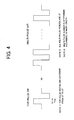
FIG. 4 is a diagram schematically showing a basic
configuration of a laser recording waveform according to the
embodiment of the present invention.
FIG. 5 is a block diagram showing a schematic configuration
of an information recording and reproducing apparatus according
to the embodiment of the present invention.
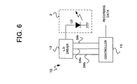
FIG. 6 is a block diagram showing a configuration of a
recording control unit shown in FIG. 5.
FIG. 7A is a circuit diagram showing a configuration of
an LD driver shown in FIG. 6, and FIG. 7B is a graph showing a
characteristic of a laser diode.
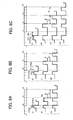
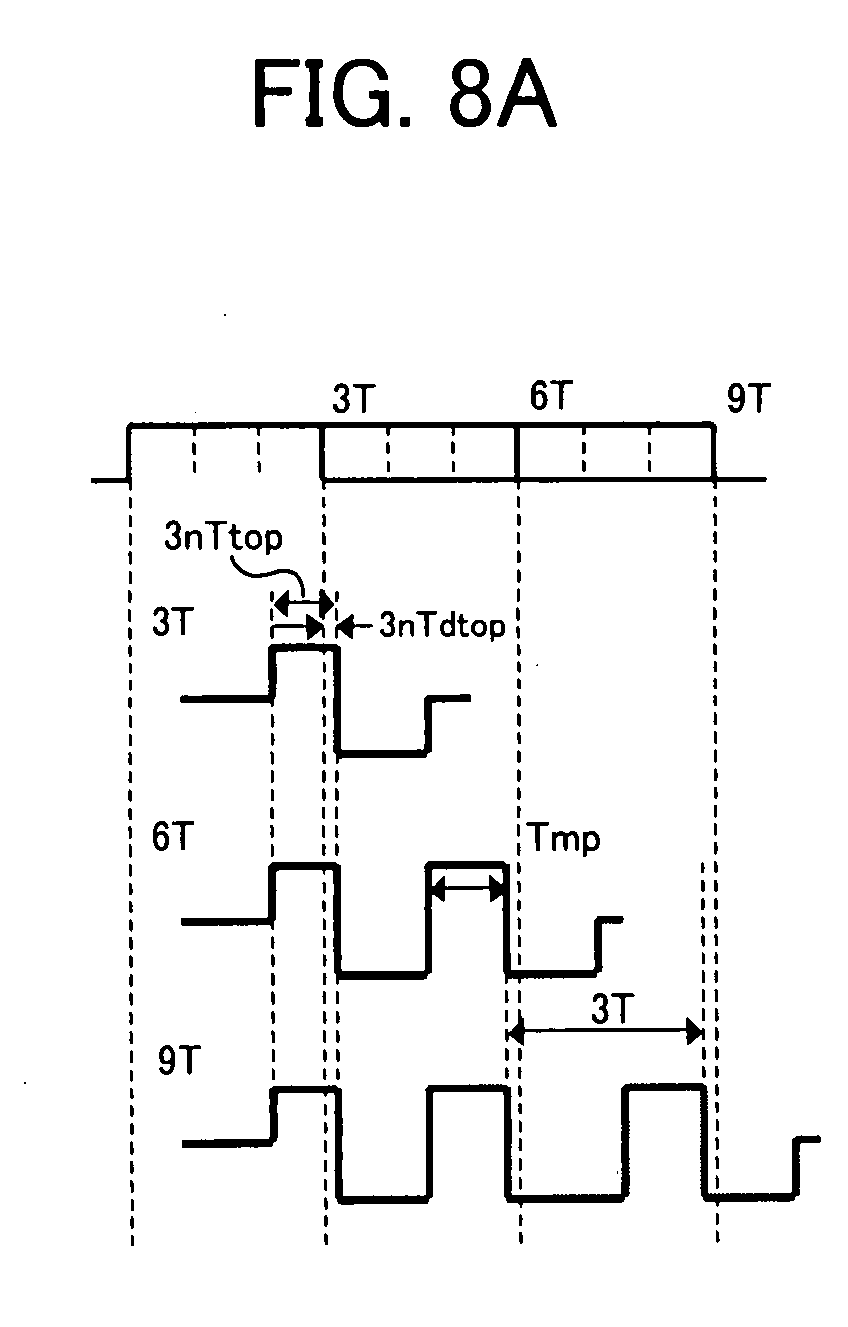
FIGS. 8A to 8C are diagrams showing laser driving waveforms
(recording strategies) according to the basic embodiment of the
present invention.
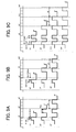
FIGS. 9A to 9C are diagrams showing laser driving waveforms
(recording strategies) according to the first modification of the
present invention.
FIGS. 10A to 10C are diagrams showing laser driving
waveforms (recording strategies) according to the second
modification of the present invention.
FIGS. 11A to 11C are diagrams showing laser driving
waveforms (recording strategies) according to the third
modification of the present invention.
FIGS. 12A to 12C are diagrams showing laser driving
waveforms (recording strategies) according to the fourth
modification of the present invention.
FIG. 13 shows pulse widths of laser driving waveforms
according to the fourth modification and setting examples of each
power level.
FIGS. 14A to 14C are diagrams showing laser driving
waveforms (recording strategies) according to the seventh
modification of the present invention.
FIGS. 15A to 15C are diagrams showing laser driving
waveforms (recording strategies) according to the eighth
modification of the present invention.
DETAILED DESCRIPTION OF THE PREFERRED EMBODIMENTS
The preferred embodiments of the present invention will
now be described below with reference to the attached drawings.
FIG. 1 shows an example of the strategy utilizing the
multi-pulses whose period is 1T. The example illustrates the
strategy of the recording data 8T and 3T. As shown in FIG. 1,
the strategy is formed by a top pulse TP, a plurality of multi-pulses
MP of 1T period and a cooling pulse CP. The number of the
multi-pulses MP is determined by a recording data length. In FIG.
1, the widths of the top pulse TP, the multi-pulse MP and the cooling
pulse CP are respectively indicated as Ttop, Tmp and Tcl.
A level of the top pulse TP varies between a recording
power level Pr and an erasing power level Pe. A level of the
multi-pulse MP varies between the recording power level Pr and
a bias power level Pb. The cooling pulse CP is equal to the bias
power level Pb, and the bias power level Pb is equal to the level
which is increased by a predetermined level from a zero level P0.
Since the multi-pulse whose period is 1T is utilized in
this strategy, the optical disc cannot be heated and cooled for
the time larger than 1T in a multi-pulse interval.
A laser emitting waveform 60 at a bottom of FIG. 1 indicates
a laser emitting waveform at the time of the high-speed recording
at which the time of 1T is smaller than 10ns. When the time of
1T becomes smaller than 10ns, the recording pulse width sometimes
becomes smaller than 5ns. For example, assuming that about 2ns
is respectively needed at rise-up and fall-down time periods of
a laser light source, as illustrated in the waveform 60, the pulse
waveform which is originally almost rectangular becomes rounded
by a transient response, and the pulse waveform cannot keep
rectangular shape. Therefore, pits cannot be accurately formed
on the disc due to the differences of the characteristics of the
laser light source and a driving circuit between the recording
apparatuses.
Based on the above-mentioned examination, in the present
invention, by setting the pulse widths of each pulse forming the
strategy to be larger than 1T, it becomes possible that the pits
are accurately formed even in the high-speed recording. Basically,
the laser driving waveform (strategy) corresponding to the
recording mark length is formed by one top pulse, necessary number
of multi-pulses corresponding to the recording mark length, and
one cooling pulse. Therefore, in a case of a short recording mark,
the laser driving waveform is formed by the combination of one
top pulse and one cooling pulse. In a case of a long recording
mark, the laser driving waveform is formed by one top pulse, the
necessary number of the multi-pulses and one cooling pulse.
When the above-mentioned laser driving waveform is utilized,
it is basically needed that the widths of the top pulse and the
multi-pulse are appropriately determined in order to correspond
to the high-speed recording. Therefore, in the present invention,
the widths of the top pulse and the multi-pulse are determined
as follows.
First of all, it is examined the recording marks of what
length can be formed by the combination of one top pulse and one
cooling pulse. FIG. 2A is a graph which shows a relation between
the width Tcl of the cooling pulse CP and the recording mark length
when the top pulse width Ttop is increased to 1.0T, 1.5T, 2.0T,
by prescribing the width Ttop of the top pulse TP as a parameter.
It is noted that the recording marks are measured after repeating
over-writing 10 times, under a condition that the recording power
Pr = 18mW and an erasing power Pe = 9mW at the recording speed
being corresponding to about 4-times speed of a DVD. The width
Tcl of the cooling pulse is varied until the marks cannot be
accurately recorded. Thus, since shapes of the recording marks
are distorted beyond a limit illustrated in the graph, and the
marks cannot be appropriately recorded, the cooling pulse width
cannot be increased further. The width Ttop of the top pulse TP
and the width Tcl of the cooling pulse CP are prescribed as shown
in FIG. 2B.
With reference to the graph in FIG. 2A, it is understood
that longer recording marks can be formed by increasing the top
pulse width Ttop and the cooling pulse width Tcl. However, no
further effect is expected even if the top pulse width Ttop is
further increased to be larger than Ttop=2.0T. No matter how long
the cooling pulse width Tcl is increased within the limit at which
the recording marks are not distorted, it is understood that only
the recording marks of at most 5T can be formed. Namely, it is
understood that the recording mark equal to or larger than 6T cannot
be formed by the combination of one top pulse TP and one cooling
pulse CP.
Next, an appropriate period of the multi-pulse is examined.
The number of the multi-pulses in the laser driving waveform depends
on the recording mark length. In order to examine that a signal
can be accurately recorded by the multi-pulse period of what length,
the recording marks of 12T are recorded by prescribing the
multi-pulse period as 3 kinds of periods, i.e., 2T, 3T and 4T
periods ,as shown in FIG. 3A. FIG. 3B is a graph which shows a
relation between a pulse duty and a signal modulating degree, as
to the recording marks of the 3 kinds of the multi-pulse periods.
Here, the pulse duty is a ratio of an H (High) level period and
an L (Low) level period in the multi-pulse period. The signal
modulating degree is a value which indicates magnitude of a
reproducing signal of the formed recording marks, and the value
of the signal modulating degree becomes large when the recording
marks are formed in accurate shapes.
With reference to the graph in FIG. 3B, when the multi-pulse
period is 2T, it is understood that the signal modulating degree
is maximum when the pulse duty is at about 0.4, while the signal
modulating degree lowers comparatively largely when the pulse duty
deviates from 0.4. On the other hand, when the multi-pulse period
is 3T and 4T, the signal modulating degree is larger than that
in a case of 2T, and the signal modulating degree comparatively
indicates a flat characteristic against a variation of the pulse
duty. Therefore, in view of the signal modulating degree, the
multi-pulse period is preferred to be 3T or 4T, and there are few
differences between the periods of 3T and 4T. However, it is
generally recognized that the formed recording marks tend to be
more easily distorted when the number of the recording pulses is
small in the long mark recording, than those when the number of
the recording pulses is large. In this point, it is recognized
that an optimum multi-pulse width is 3T.
According to the above-mentioned examination, it is found
out as follows: (1) the recording marks which are at least equal
to or larger than 6T mark should be formed by the combination of
the top pulse, the necessary number of the multi-pulses and the
cooling pulse, and (2) it is preferred that the optimum multi-pulse
width is 3T. As a result, it is understood that the preferred
laser driving waveform (strategy) in the high-speed recording are
the waveform having the top pulse and cooling pulse of pulse widths
corresponding to the recording mark length as to the recording
marks 3T to 5T, and the waveform having the top pulse, the
multi-pulses of 3T period whose number corresponds to the recording
mark length and the cooling pulse as to the recording marks equal
to or larger than 6T, as schematically shown in FIG. 4. In this
invention, it is possible to accurately form the recording marks
even at the time of the high-speed recording, by utilizing such
a strategy.
According to one aspect of the present invention, there
is provided an information recording apparatus including a signal
generating unit which generates a light source driving signal having
a top pulse and multi-pulse of a necessary number corresponding
to a recording mark length of recording data, and a recording unit
which irradiates a recording light on an optical recording medium
by driving a light source based on the light driving signal and
forms recording marks on the optical recording medium, wherein
the signal generating unit includes, a multi-pulse generating unit
which generates a multi-pulse having a period 3-times larger than
a base clock period T of the recording mark, and a top pulse generating
unit which generates first identical-shape top pulses when the
recording mark length is 3nT ("n" is an integral number), and second
identical-shape top pulses when the recording mark length is (3n+1) T,
and third identical-shape top pulses when the recording mark length
is (3n+2) T. According to the above information recording apparatus,
since the period of the multi-pulse is 3-times larger than the
base clock period T of the recording mark, the recording can be
accurately executed at the time of the high-speed recording.
In the above-mentioned information recording apparatus,
the light source driving signal may include only the top pulse
when the recording mark length is from 3T to 5T. The second top
pulse width may be larger than the first top pulse width, and the
third top pulse width may be larger than the second top pulse width.
In one feature of the above information recording apparatus,
the third top pulse may be formed by two pulses. Thus, even when
the recording marks cannot be preferably formed by one top pulse
due to a recording characteristic of the optical disc subjected
to recording, the recording marks can be preferably formed by two
pulses.
In another feature of the above information recording
apparatus, by making a back edge position of the multi-pulse
correspond to the base clock position, back positions of the long
recording marks are easy to align, and the recording with less
recording and reproducing jitter is possible. Further, by making
the cooling pulse portion width of the last multi-pulse included
in the light source driving waveform corresponding to the recording
marks equal to or larger than 6T constant, it is possible that
back positions of the long recording marks are much easier to align.
In the above information recording apparatus, preferably,
the back edges of two pulses forming the third top pulse may
respectively correspond to the positions of 3T and 5T from rise-up
of the recording data. Also, the top pulse width and the multi-pulse
width may be equal to or larger than 0.5T.
In the above information recording apparatus, a time from
rise-up of the recording data to a rise-up of the top pulse may
be constant, irrespective of the recording mark length. Thus,
the head positions of the recording marks are easy to align, and
the recording with less recording and reproducing jitter is
possible.
Moreover, in the above information recording apparatus,
by making the power levels of the first to the third top pulses
different from each other, preferable recording adapted to the
recording characteristic of the optical disc is possible by
adjusting not only the pulse width but also the recording power.
Next, the preferred embodiments of the present invention
will be described below with reference to the attached drawings.
[Configuration of Information Recording and Reproducing Apparatus]
FIG. 5 schematically shows the whole configuration of the
information recording and reproducing apparatus according to the
embodiment of the present invention. An information recording
and reproducing apparatus 1 records information on an optical disc
D, and reproduces the information from the optical disc D. As
the optical disc D, for example, a CD-RW (Compact Disc-Rewritable)
or a DVD-RW, which are capable of erasing and recording the
information a plurality of times, may be used.
The information recording and reproducing apparatus 1
includes an optical pickup 2 which irradiates a recording beam
and a reproducing beam on the optical disc D, a spindle motor 3
which controls rotation of the optical disc D, a recording control
unit 10 which controls the recording of the information on the
optical disc D, a reproducing control unit 20 which controls
reproduction of the information already recorded on the optical
disc D, a spindle servo which controls rotation of the spindle
motor 3, and a servo control unit 30 which executes various kinds
of servo control including a focus servo and a tracking servo,
both of width are relative position control of the optical pickup
2 to the optical disc D.
The recording control unit 10 receives the recording data
and generates a driving signal SD for driving a laser diode inside
the optical pickup 2 by a process described below, and supplies
the signal SD to the optical pickup 2.
The reproducing control unit 20 receives a read-out RF
signal Srf which is output from the optical pickup 2, and generates
and outputs reproducing data by executing a predetermined
demodulating process and decoding process to the signal Srf.
The servo control unit 30 receives the read-out RF signal
Srf from the optical pickup 2, and, based on the signal, supplies
a servo signal S1, such as a tracking error signal and a focus
signal, to the optical pickup 2, and also supplies a spindle servo
signal S2 to the spindle motor 3. Thus, various kinds of servo
processes, such as a tracking servo, a focus servo and a spindle
servo, are executed.
The present invention mainly relates to a method of the
recording in the recording control unit 10, and various kinds of
known methods can be applied, as to the reproducing control and
the servo control. Therefore, an explanation thereof is not given
in detail here.
Though FIG. 5 illustrates the information recording and
reproducing apparatus as an example of the embodiment of the present
invention, it is also possible to apply the present invention to
an information recording apparatus dedicated to recording.
FIG. 6 shows an internal configuration of the optical pickup
2 and the recording control unit 10. As shown in FIG. 6, the optical
pickup 2 includes a laser diode LD which generates the recording
beam for recording the information to the optical disc D and the
reproducing beam for reproducing the information from the optical
disc D.
The optical pickup 2 additionally includes well-known
components such as a light detector which receives a reflected
beam by the optical disc D of the reproducing beam and generates
the read-out RF signal Srf, and an optical system which guides
the recording beam, the reproducing beam and the reflected beam
to appropriate directions. However, drawings and detailed
explanations thereof are omitted here.
On the other hand, the recording control unit 10 includes
a laser diode (LD) driver 12 and a controller 15. The LD driver
12 supplies a current corresponding to the recording signal to
the laser diode LD, and records the information on the optical
disc D.
FIG. 7A shows a detailed configuration of the LD driver
12. As shown in FIG. 7A, the LD driver 12 includes a current source
17b for the bias power level, a current source 17e for the erasing
power level, a current source 17r for the recording power level,
switches 18b, 18e and 18r.
The current source 17b for the bias power level generates
the flow of a driving current Ib for driving the laser diode LD
to emit the laser light with the bias power Pb, and the driving
current Ib is supplied to the laser diode LD via the switch 18b.
Thus, when the switch 18b is switched on, the driving current Ib
of the bias power is supplied to the laser diode LD, and when the
switch 18b is switched off, the driving current Ib is not supplied.
The current source 17e for the erasing power level generates
the flow of the driving current 11 for driving the laser diode
LD to emit the laser light with the erasing power Pe. The driving
current 11 is supplied to the laser diode LD via the switch 18e.
The driving current I1 is added to the driving current Ib of the
bias power, and the driving current Ie of the erasing power is
supplied to the laser diode LD via the switch 18e.
The current source 17r for the recording power level
generates the flow of the driving current 12 for driving the laser
diode LD to emit the laser light with the recording power Pr. The
driving current 12 is supplied to the laser diode LD via the switch
18r. The driving current 12 is added to the driving current Ib
of the bias power, and the driving current Ir of the recording
power is supplied to the laser diode LD via the switch 18r.
Therefore, by controlling the ON/OFF of the switches 18b,
18e, and 18r, the laser diode LD serving as the laser light source
can be driven with any one of the bias power Pb, the erasing power
Pe or the recording power Pr.
FIG. 7B shows a relation between the driving current
supplied to the laser diode LD and an output power of the laser
light emitted from the laser diode LD. As understood in FIG. 7B,
when the driving current Ib is supplied to the laser diode LD,
the laser light is emitted by the bias power Pb. Moreover, when
the driving current I1 is added under the condition, the laser
light is emitted by the erasing power Pe. When the driving current
12 is added instead of the driving current 11, the laser light
is emitted by the recording power Pr.
[Embodiment of Strategy]
Next, the description will be given of the embodiment of
the strategy for the high-speed recording according to the present
invention.
(Basic Embodiment)
FIGS. 8A to 8C show the strategy according to a basic
embodiment. The recording marks to be recorded on the disc,
corresponding to the recording data, are 3T to 11T and 14T, and
FIGS. 8A to 8C show the laser driving waveform corresponding to
each recording mark length. In the embodiment of the present
invention, the recording mark lengths 3T to 11T and 14T are
classified into three groups. Concretely, as shown in FIGS. 8A
to 8C, the lengths are classified into a group G1 of the recording
mark length = 3nT, a group G2 of the recording mark length = (3n+1) T,
and a group G3 of the recording mark length = (3n+2) T. It is noted
that "n" is a positive integral number from 1 to 4.
Namely, the recording mark lengths 3T, 6T and 9T belong
to the group G1, and the laser driving waveforms thereof are
illustrated in FIG. 8A. The recording mark lengths 4T, 7T and
10T belong to the group G2, and the laser driving waveforms thereof
are illustrated in FIG. 8B. The recording mark lengths 5T, 8T
and 11T belong to the group G3, and the laser driving waveforms
thereof are illustrated in FIG. 8C. It is noted that the base
clocks (1T period) of the recording data are indicated at the top
of each drawing.
As explained above, the laser driving waveforms
corresponding to the recording mark lengths 3T to 5T are formed
by the combination of the top pulse TP and the cooling pulse CP,
and no multi-pulses are included. Also, in the laser driving
waveforms of the recording mark lengths 3T to 5T, the top pulse
width Ttop and the cooling pulse width Tcl are determined according
to the recording mark lengths. Namely, the top pulse width Ttop
and the cooling pulse width Tcl are shortest at 3T, middle at 4T
and longest at 5T.
The laser driving waveforms of the recording mark lengths
6T to 8T are respectively formed by the top pulse, the cooling
pulse and one multi-pulse. The laser driving waveforms of the
recording mark lengths 9T to 11T are respectively formed by the
top pulse, the cooling pulse, and two multi-pulses. The laser
driving waveform of the recording mark length 14T is formed by
the top pulse, the cooling pulse and three multi-pulses.
As understood in FIGS. 8A to 8C, as to the recording mark
length belonging to each group, the shapes of the top pulses are
identical and regularly formed. Namely, the laser driving
waveforms of the recording mark lengths 3T, 6T and 9T belonging
to the group G1 have the identical-shape top pulses, and the laser
driving waveforms of the recording mark lengths 4T, 7T and 10T
belonging to the group G2 have the identical-shape top pulses.
The laser driving waveforms of the recording mark lengths 5T, 8T,
11T and 14T belonging to the group G3 have the identical-shape
top pulses.
Further, all the laser driving waveforms of the recording
mark lengths equal to or larger than 6T, each including one or
more multi-pulse have the identical-shape multi-pulses whose
periods are 3T. The aforementioned conclusion that the optimum
multi-pulse period is 3T is reflected in this point.
As explained above, in the embodiment, based on the
above-mentioned examined result, the laser driving waveforms of
the recording marks equal to or smaller than 5T are formed by the
combination of the top pulse and the cooling pulse, and the top
pulse width and the cooling pulse width are determined according
to the recording mark lengths. The laser driving waveforms of
the recording marks equal to or larger than 6T are formed by the
top pulse, the multi-pulses whose number corresponds to the
recording mark lengths, and the cooling pulse. Thus, it is possible
to form pits of accurate shape at the time of the high-speed
recording.
(1st Modification)
Next, the strategy according to the first modification
will be explained. FIGS. 9A to 9C show the laser driving waveform
of each recording mark length according to the first modification.
The first modification is different from the basic embodiment in
that the top pulse TP is formed by the two pulses for the recording
mark belonging to the group G3. In the first modification, the
laser driving waveforms of the recording mark lengths belonging
to the groups G1 and G2 are identical to those of the basic embodiment
shown in FIGS. 8A to 8C.
As to the recording marks belonging to the group G3, i.e. ,
5T, 8T, 11T and 14T, it is determined whether the top pulse TP
is one, like the basic embodiment shown in FIGS. 8A to 8C, or two,
like the first modification, dependently on the recording
characteristic of the optical disc subjected to the recording.
Namely, the first modification is effective when 5T mark can not
be preferably formed by only a pair of the top pulse TP and the
cooling pulse CP like the basic embodiment, or when distortion
occurs to the marks 8T, 11T and 14T by only one top pulse TP.
(2nd Modification)
Next, the strategy according to the second modification
will be explained. FIGS. 10A to 10C show the laser driving waveform
of each recording mark according to the second modification. As
shown in FIGS. 10A to 10C, the back edge of the multi-pulse train
of the recording mark equal to or larger than 6T corresponds to
the base clock of 1T period in the second modification. Because
of this, since the back end positions of the long recording marks
are easy to align with each other, the recording with less recording
and reproducing jitter is possible.
(3rd Modification)
Next, the strategy according to the third modification
will be explained. FIGS. 11A to 11C show the laser driving waveform
of each recording mark according to the third modification. In
the third modification, in addition to the basic embodiment shown
in FIGS. 8A to 8C, first of all, identically to the second
modification shown in FIGS. 10A to 10C, the back edge of the
multi-pulse train of the recording mark equal to or larger than
6T corresponds to the base clock of 1T period, and further, the
width of the cooling pulse portion of the last multi-pulse in the
laser driving waveform of the recording mark equal to or larger
than 6T is made identical. Namely, as shown in FIGS. 11A to 11C,
for all the recording marks equal to or larger than 6T, the width
of the cooling pulse portion of the last multi-pulse is set to
"W".
According to the third embodiment, while the position of
the short recording mark which is formed by the combination of
the top pulse and the cooling pulse is kept adjustable, the back
positions of the long recording marks are easier to align than
that in the second modification, and the preferable recording with
less recording and reproducing jitter is possible.
(4th Modification)
Next, the strategy according to the fourth modification
will be explained. FIGS. 12A to 12C show the laser driving waveform
of each recording mark according to the fourth modification. In
the fourth modification, first of all, identically to the first
modification shown in FIGS. 9A to 9C, the top pulses of the recording
marks 5T, 8T, 11T and 14T belonging to the group G3 are respectively
formed by two pulses. The back edges of two top pulses of the
laser driving waveform of the recording mark belonging to the group
G3 are respectively adjusted to the positions of 3T and 5T from
the rise-up of the recording data. Moreover, identically to the
third modification, the back edge of the multi-pulse train of the
recording mark equal to or larger than 6T corresponds to the base
clock of 1T, and the width of the cooling pulse portion of the
last multi-pulse in the laser driving waveform of the recording
mark equal to or larger than 5T is made identical ("W").
According to the fourth modification, while the positions
of the recording marks 3T and 4T which are formed by the combination
of the top pulse and the cooling pulse are kept adjustable, the
back position of the long recording mark is much easier to align
than the second modification, and the preferable recording with
less recording and reproducing jitter is possible.
A table in FIG. 13 shows an example of each value in the
laser driving waveform in the fourth modification. FIG. 13 shows
two examples of the recording speed corresponding to 4-times higher
speed of the DVD. It is noted that sign of 3nTdtop and (3n+1) Tdtop
is indicated as positive when the back edge of the top pulse is
ahead of the base clock (i.e., it shifts to the left side), and
the sign is indicated as negative when the back edge of the top
pulse is behind of the base clock (i.e., it shifts to the right
side).
(5th Modification)
Next, the fifth modification will be explained. The fifth
modification is a case that the pulse widths of the top pulse TP
and multi-pulse MP of the basic embodiment shown in FIGS. 8A to
8C are limited. Concretely, they are determined as follows,
As explained above, for example, 1T is equal to about 10ns,
and 0.5T is equal to about 5ns in 4-times higher speed recording
of the DVD. Since the pulse width smaller than 5ns is too narrow
as shown in FIG. 1, the recording marks cannot be accurately formed.
That is why each top pulse width and multi-pulse width is determined
to be larger than 0.5T. In addition, since an L-level period of
the multi-pulse becomes equal to or smaller than 0.5T if the
multi-pulse width is equal to or larger than 2. 5T, the multi-pulse
width is determined to be smaller than 2.5T.
Like this, by limiting the pulse width in each portion
of the laser driving waveform, it is possible that the recording
is executed in an area in which an accurate laser emitting waveform
is obtained.
(6th Modification)
Next, the sixth modification will be explained. The sixth
modification is a case that the pulse widths of the top pulse TP
and the multi-pulse MP in the first modification shown in FIGS.
9A to 9C are limited. Concretely, they are determined as follows,
Here, the reason why each top pulse width and multi-pulse
width is determined to be equal to or larger than 0.5T is identical
to the reason which is mentioned in the fifth modification. As
understood in FIGS. 7A and 7B, since the top pulse in the group
G3 is formed by two pulses in the first modification, a range of
the pulse width is set for each pulse. Thus, by limiting the pulse
width in each portion of the laser driving waveform, it is possible
that the recording is executed in the area in which the accurate
laser emitting waveform is obtained in the sixth modification,
too.
(7th Modification)
Next, the seventh modification will be explained. The
seventh modification is a case that a time Td from the rise-up
of the recording data to the rise-up of the top pulse is set to
be constant, irrespective of the recording mark length, in the
above-mentioned basic embodiment and the first to sixth
modifications. As an example, FIGS. 14A to 14C show the laser
recording waveforms of a case that the seventh modification is
applied to the fourth modification shown in FIGS. 12A to 12C. As
shown in FIGS. 14A to 14C, irrespective of the recording mark length,
the time Td from the rise-up of the recording data to the rise-up
of the top pulse is constant in all the laser recording waveforms.
Thus, since the rise-up positions of the top pulses are aligned
in all the recording marks in the seventh modification, the head
position of each recording mark is easy to align with each other,
and the preferable recording with less recording and reproducing
jitters is possible.
(8th Modification)
Next, the eighth modification will be explained. The
eighth modification is a case that the recording power level of
each top pulse portion in three groups G1 to G3 are set to be different
from each other for the above-mentioned basic embodiment and the
first to seventh modifications. FIGS. 15A to 15C show the laser
driving waveforms of a case that the eighth modification is applied
to the basic modification shown in FIGS. 8A to 8C. As understood
in FIGS. 15A to 15C, the recording power level of the top pulse
in each group G1 to G3 is
3nTPw ≤ (3n+1) TPw ≤ (3n+2) TPw,
if it is defined that the recording power level of the top pulse
in the group G1 is "3nTPw", the recording power level of the top
pulse in the group G2 is " (3n+1) TPw", and the recording power level
of the top pulse in the group G3 is "(3n+2)TPw".
Thus, in the eighth modification, by adjusting the
recording power to adapt to the recording characteristic of the
optical disc subjected to the recording in addition to the pulse
width, the preferable recording adapted to the recording
characteristic of the optical disc is possible.
Though examples shown in FIGS. 15A to 15C indicate examples
that the recording power levels becomes larger in the order of
the groups G1 to G3, an application of the eighth embodiment is
not limited to this. Namely, the recording power level can be
suitably determined according to the pulse width of each portion
in the laser driving waveform of each group.
INDUSTRIAL APPLICABILITY
The information recording apparatus and the information
recording method according to this invention can be used at the
time of recording the information onto the optical disc by using
the laser light and the like.