EP1598808A1 - Sound-absorbing structure using thin film - Google Patents
Sound-absorbing structure using thin film Download PDFInfo
- Publication number
- EP1598808A1 EP1598808A1 EP04704720A EP04704720A EP1598808A1 EP 1598808 A1 EP1598808 A1 EP 1598808A1 EP 04704720 A EP04704720 A EP 04704720A EP 04704720 A EP04704720 A EP 04704720A EP 1598808 A1 EP1598808 A1 EP 1598808A1
- Authority
- EP
- European Patent Office
- Prior art keywords
- sound
- thin film
- absorbing structure
- structure according
- thin films
- Prior art date
- Legal status (The legal status is an assumption and is not a legal conclusion. Google has not performed a legal analysis and makes no representation as to the accuracy of the status listed.)
- Withdrawn
Links
Images






Classifications
-
- G—PHYSICS
- G10—MUSICAL INSTRUMENTS; ACOUSTICS
- G10K—SOUND-PRODUCING DEVICES; METHODS OR DEVICES FOR PROTECTING AGAINST, OR FOR DAMPING, NOISE OR OTHER ACOUSTIC WAVES IN GENERAL; ACOUSTICS NOT OTHERWISE PROVIDED FOR
- G10K11/00—Methods or devices for transmitting, conducting or directing sound in general; Methods or devices for protecting against, or for damping, noise or other acoustic waves in general
- G10K11/16—Methods or devices for protecting against, or for damping, noise or other acoustic waves in general
-
- B—PERFORMING OPERATIONS; TRANSPORTING
- B32—LAYERED PRODUCTS
- B32B—LAYERED PRODUCTS, i.e. PRODUCTS BUILT-UP OF STRATA OF FLAT OR NON-FLAT, e.g. CELLULAR OR HONEYCOMB, FORM
- B32B3/00—Layered products comprising a layer with external or internal discontinuities or unevennesses, or a layer of non-planar shape; Layered products comprising a layer having particular features of form
- B32B3/26—Layered products comprising a layer with external or internal discontinuities or unevennesses, or a layer of non-planar shape; Layered products comprising a layer having particular features of form characterised by a particular shape of the outline of the cross-section of a continuous layer; characterised by a layer with cavities or internal voids ; characterised by an apertured layer
- B32B3/30—Layered products comprising a layer with external or internal discontinuities or unevennesses, or a layer of non-planar shape; Layered products comprising a layer having particular features of form characterised by a particular shape of the outline of the cross-section of a continuous layer; characterised by a layer with cavities or internal voids ; characterised by an apertured layer characterised by a layer formed with recesses or projections, e.g. hollows, grooves, protuberances, ribs
-
- B—PERFORMING OPERATIONS; TRANSPORTING
- B32—LAYERED PRODUCTS
- B32B—LAYERED PRODUCTS, i.e. PRODUCTS BUILT-UP OF STRATA OF FLAT OR NON-FLAT, e.g. CELLULAR OR HONEYCOMB, FORM
- B32B3/00—Layered products comprising a layer with external or internal discontinuities or unevennesses, or a layer of non-planar shape; Layered products comprising a layer having particular features of form
- B32B3/26—Layered products comprising a layer with external or internal discontinuities or unevennesses, or a layer of non-planar shape; Layered products comprising a layer having particular features of form characterised by a particular shape of the outline of the cross-section of a continuous layer; characterised by a layer with cavities or internal voids ; characterised by an apertured layer
- B32B3/266—Layered products comprising a layer with external or internal discontinuities or unevennesses, or a layer of non-planar shape; Layered products comprising a layer having particular features of form characterised by a particular shape of the outline of the cross-section of a continuous layer; characterised by a layer with cavities or internal voids ; characterised by an apertured layer characterised by an apertured layer, the apertures going through the whole thickness of the layer, e.g. expanded metal, perforated layer, slit layer regular cells B32B3/12
-
- B—PERFORMING OPERATIONS; TRANSPORTING
- B32—LAYERED PRODUCTS
- B32B—LAYERED PRODUCTS, i.e. PRODUCTS BUILT-UP OF STRATA OF FLAT OR NON-FLAT, e.g. CELLULAR OR HONEYCOMB, FORM
- B32B7/00—Layered products characterised by the relation between layers; Layered products characterised by the relative orientation of features between layers, or by the relative values of a measurable parameter between layers, i.e. products comprising layers having different physical, chemical or physicochemical properties; Layered products characterised by the interconnection of layers
-
- G—PHYSICS
- G10—MUSICAL INSTRUMENTS; ACOUSTICS
- G10K—SOUND-PRODUCING DEVICES; METHODS OR DEVICES FOR PROTECTING AGAINST, OR FOR DAMPING, NOISE OR OTHER ACOUSTIC WAVES IN GENERAL; ACOUSTICS NOT OTHERWISE PROVIDED FOR
- G10K11/00—Methods or devices for transmitting, conducting or directing sound in general; Methods or devices for protecting against, or for damping, noise or other acoustic waves in general
- G10K11/16—Methods or devices for protecting against, or for damping, noise or other acoustic waves in general
- G10K11/162—Selection of materials
- G10K11/168—Plural layers of different materials, e.g. sandwiches
-
- G—PHYSICS
- G10—MUSICAL INSTRUMENTS; ACOUSTICS
- G10K—SOUND-PRODUCING DEVICES; METHODS OR DEVICES FOR PROTECTING AGAINST, OR FOR DAMPING, NOISE OR OTHER ACOUSTIC WAVES IN GENERAL; ACOUSTICS NOT OTHERWISE PROVIDED FOR
- G10K11/00—Methods or devices for transmitting, conducting or directing sound in general; Methods or devices for protecting against, or for damping, noise or other acoustic waves in general
- G10K11/16—Methods or devices for protecting against, or for damping, noise or other acoustic waves in general
- G10K11/172—Methods or devices for protecting against, or for damping, noise or other acoustic waves in general using resonance effects
-
- B—PERFORMING OPERATIONS; TRANSPORTING
- B32—LAYERED PRODUCTS
- B32B—LAYERED PRODUCTS, i.e. PRODUCTS BUILT-UP OF STRATA OF FLAT OR NON-FLAT, e.g. CELLULAR OR HONEYCOMB, FORM
- B32B2307/00—Properties of the layers or laminate
- B32B2307/10—Properties of the layers or laminate having particular acoustical properties
- B32B2307/102—Insulating
Definitions
- the present invention relates to a technique of a sound-absorbing structure using a thin film.
- Patent Document 1 Japanese Patent Laid Open No. 2002-59510
- Patent Document 2 Japanese Patent Laid Open No. 2000-34937
- Patent Documents 1 and 2 are each concerned with a sound-absorbing structure using a sound-absorbing material which is a combination of a porous sound-absorbing material such as glass wool and a material excellent in weather resistance, water resistance and heat resistance.
- a sound-absorbing structure including at least a first thin film and a second thin film, the first thin film and the second thin film being layered over each other and one or both of the first thin film and the second thin film having at least either ridges or grooves.
- the thin films vibrate upon incidence of a sound wave on the sound-absorbing structure of the present invention and their overlapping portions contact and are rubbed against each other. As a result, there occurs energy dissipation of the sound wave and a high sound absorption coefficient is attained in a wide band.
- a sound absorbing structure including at least a first thin film and a second thin film, the first thin film and the second thin film being layered over each other and one or both of the first thin film and the second thin film being folded so as to have mutually contacting and overlapping portions.
- the first and second thin films vibrate, contact (including their overlapping portions) and are rubbed against each other. As a result, there occurs energy dissipation of the sound wave and a high sound absorption coefficient is attained in a wide band.
- a sound-absorbing structure including at least a first thin film and a second thin film, the first thin film and the second thin film being layered over each other, and through holes being formed in one or both of the first thin film and the second thin film.
- the thin films Upon incidence of a sound wave on the sound-absorbing structure of the present invention, the thin films vibrate and their overlapping portions contact and are rubbed against each other. As a result, there occurs energy dissipation of the sound wave and a high sound absorption coefficient is attained in a wide band. Moreover, a higher sound absorbing effect can be attained because a damping effect is added when the sound wave passes through the through holes.
- a metallic thin film such as aluminum foil or a resinous thin film such as a polyvinyl chloride film is employable as each of the thin films.
- a sound absorbing structure including at least one thin film folded so as to have mutually contacting and overlapping portions.
- the thin film Upon incidence of a sound wave on the sound-absorbing structure of the present invention, the thin film vibrates and their overlapping portions contact and are rubbed against each other. As a result, there occurs energy dissipation of the sound wave and a high sound absorption coefficient is attained in a wide band.
- a metallic thin film such as aluminum foil or a resinous thin film such as a polyvinyl chloride film is employable as the thin film.
- a sound-absorbing structure including at least a first thin film and a second thin film, the first thin film and the second thin film being layered over each other, and an air-permeable front member being installed at a position on the sound wave incidence side with respect to the thin films.
- the front member Since the front member is air-permeable, it does not shut off an incident sound wave and hence does not obstruct the sound absorbing effect.
- a first thin film 11 and a second thin film 12 are layered over each other.
- the thin films 11 and 12 there may be used, for example, a metallic thin film such as aluminum foil or a resinous thin film such as a polyvinyl chloride film, but no limitation is made thereto.
- each of the two thin films 11 and 12 has a large number of ridges (a) which face one side in the layered direction of the thin films.
- Fig. 2 shows an effect of this embodiment.
- the thin films 11 and 12 vibrate and their overlapping portions contact and are rubbed against each other as shown in Fig. 2(b), with the result that there occurs energy dissipation of the sound wave and absorption of sound is effected.
- the ridges (a) are not shown for the convenience of explanation.
- This embodiment adopts a mechanism that the two thin films 11 and 12 vibrate upon the incidence of the sound wave, contact and are rubbed against each other to dissipate energy of the sound wave.
- an excellent sound absorbing capacity can be exhibited in a wide band as compared with a configuration wherein the energy is dissipated using a resonance phenomenon.
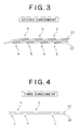
- Fig. 3 shows a sound-absorbing structure according to a second embodiment of the present invention, which is the same as the first embodiment in that two thin films 21 and 22 are layered over each other.
- the two thin films 21 and 22 are each folded so as to have mutually contacting and overlapping portions (b) instead of forming such ridges (a) as described above.
- the two thin films 21 and 22 also vibrate upon incidence of a sound wave and both films (including their folded portions (b)) contact and are rubbed against each other, whereby energy of the sound wave can be dissipated and a high sound absorption coefficient can be attained in a wide band.
- Fig. 4 shows a sound-absorbing structure according to a third embodiment of the present invention, which is the same as the previous embodiments in that two thin films 31 and 32 are layered over each other.
- each of the two thin films 31 and 32 is formed with fine through holes (c) extending in the film thickness direction through the film.
- the through holes (c) in the first thin film 31 are formed in positions not overlapping the through holes (c) formed in the second thin film 32. That is, the through holes (c) of one thin film (31 or 32) are formed in positions not overlapping the through holes (c) of the other thin film (32 or 31).
- a more excellent sound deadening effect can be obtained not only because there is obtained the same effect as in the previous first and second embodiments, i.e., excellent sound deadening effect in a wide band resulting from vibration and mutual rubbing of the thin films 31 and 32, but also because the sound wave is further damped during passage thereof through the through holes (c).
- through holes (c) used in this embodiment are fine holes, the above damping effect is further improved, that is, there is attained a remarkable improvement of the sound deadening effect.
- the sound wave as shown in Fig. 5, passes from the incidence side through the through holes (c) of the first thin film 31, then passes between the two thin films 31 and 32 and goes out through the through holes (c) of the second thin film 32.
- the sound wave propagates along inner surfaces of the two thin films 31 and 32 as in Fig. 5, so that a damping action induced during passage of the sound wave through the through holes (c) and a viscous damping action induced during propagation of the sound wave along the surfaces of both thin films 31 and 32 are combined to let a still higher sound deadening effect be exhibited.
- the through holes (c) may also be formed in the thin films used in the previous first and second embodiments or in the following fourth embodiment, whereby the sound deadening effect can be further improved.
- Fig. 6 shows a sound-absorbing structure according to a fourth embodiment of the present invention.
- This sound-absorbing structure is constituted by using a single thin film 41.
- the thin film 41 is folded so as to have mutually contacting and overlapping portions (b). Therefore, when the overlapping portions (b) contact and are rubbed against each other, energy of the sound wave can be dissipated and it is possible to attain a high sound absorption coefficient in a wide band.
- the sound-absorbing structure of this embodiment can be attained by using only one thin film 41, there is an advantage that a manufacturing cost can be reduced.
- Fig. 7 shows a sound-absorbing structure according to a fifth embodiment of the present invention.
- a rear member 50 is installed on the side opposite to the sound wave incidence side with respect to the thin films 31 and 32.
- a sound deadening effect can be further improved not only because the effect of the third embodiment can be equally attained, but also because a sound wave can be damped by utilizing a resonance phenomenon of the sound wave which occurs between the thin films 31, 32 and the rear member 50.
- the sound wave of a frequency corresponding to the thickness of the air layer present between the rear member 50 and the thin films 31, 32 can be damped particularly strongly. Consequently, it becomes possible to adopt a mode of use such that a distance L between the rear member 50 and the thin films 31 and 32 is adjusted to strongly damp the sound wave of or near a desired frequency.
- the thin films 31 and 32 used in the third embodiment are used in this fifth embodiment, the thin films used in the first, second or fourth embodiment may be used instead.
- flat thin films free of ridges, grooves or holes, and unfolded thin films are also employable. This is also the case with the following sixth and subsequent embodiments.
- a sound-absorbing structure according to a sixth embodiment of the present invention is shown in Fig. 8.
- the configuration of the previous fifth embodiment is provided with a front member 60 as a protecting member disposed on the sound wave incidence side of the thin films 31 and 32.
- the front member 60 possesses air permeability and is installed on the sound wave incidence side of the sound-absorbing structure shown in Fig. 4 in order to protect the thin films 31 and 32 together with the rear member 50.
- the air-permeable front member there are a perforated plate and an expanded metal, but no limitation is made thereto.
- the front member 60 is air-permeable, it does not shut off an incident sound wave and hence does not obstruct the sound absorbing effect.
- Fig. 9 shows a sound-absorbing structure according to a seventh embodiment of the present invention, in which the front member 60 used in the previous sixth embodiment is replaced by a member (porous member) 70 formed with a large number of fine holes.
- the porous member 70 not only can protect the thin films 31 and 32 like the front member 60 used in the previous sixth embodiment, but also brings about a sound wave damping effect during passage of a sound wave through the porous member 70 and can thereby further improve the sound absorbing capacity.
- Fig. 10 shows sound-absorbing structures according to an eighth embodiment of the present invention.
- a space between the porous member 70 and the rear member 50 in the seventh embodiment is divided in the surface direction of the thin films 31 and 32.
- the space between the porous member 70 and the rear member 50 is partitioned in the surface direction of the thin films 31 and 32 by plural partition members 80 to form plural cells 81.
- the partition members 80 may be installed perpendicularly to the thin films 31 and 32 as in Fig. 9(a) or may be inclined with respect to the direction perpendicular to the thin films 31 and 32 as in Fig. 9(b).
- resonance type sound-absorbing structures whereby the sound absorbing effect is particularly improved in a low frequency range.
- Fig. 11 shows a sound-absorbing structure according to a ninth embodiment of the present invention.
- the thin films 31, 32, rear member 50 and porous member 70 used in the eighth embodiment are separated along the partition members 80 into individual cells 81.
- a sound-absorbing structure including a suitable combination of three or more thin films can also exhibit equal or even higher sound absorbing capacity.
- sound-absorbing structures each including a combination of plural thin films such as a sound-absorbing structure including the thin films 11 and 12 shown in Fig. 1 with another thin film (any of the thin films described in the above embodiments, a thin film having neither ridges or grooves nor holes, an unfolded thin film) or the like, a sound-absorbing structure including another thin film sandwiched in between the thin films 21 and 22 shown in Fig. 3, and a sound-absorbing structure including the thin films 31 and 32 shown in Fig. 4 with the thin films 11 and 12 shown in Fig. 1.
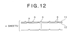
- Fig. 12 is shown a structure wherein n sheets (n ⁇ 3) of the thin films used in the first embodiment of Fig. 1 are layered over one another
- Fig. 13(a) is shown a structure wherein n sheets (n ⁇ 3) of the thin films used in the sixth embodiment of Fig. 8 are layered over one another
- Fig. 13(b) is shown a structure wherein stacks each comprising plural sheets of the thin films used in the sixth embodiment of Fig. 8 are formed in n layers (n ⁇ 2) while forming an air layer between adjacent layers.
- Fig. 14 is shown a structure wherein n sheets (n ⁇ 3) of the thin films used in the eighth embodiment of Fig. 10 are stacked or a structure wherein stacks each comprising plural thin films are formed in m layers (m ⁇ 2) with an air layer between adjacent layers.
- the thin films used in the above embodiments may be different materials.
- Fig. 15 shows an apparatus used in the experiment.
- a rigid wall 101 (corresponding to the rear member 50) is installed behind a double aluminum foil 100 through an air layer, and a sound wave is applied from a speaker 102 to a surface of the aluminum foil 100 located on the opposite side to the rigid wall 101. Sound pressure is measured by sound pressure measuring devices 111 and 112 at two points ahead of the double aluminum foil 100 to determine a reflected wave against an incident wave on the double aluminum foil 100. In this way, it is possible to measure a sound absorption coefficient of the double aluminum foil 100.
- Fig. 16 shows results of an experiment which has been conducted using a perforated double aluminum foil 100 (corresponding to the fifth embodiment). More specifically, aluminum foils having a large number of holes (corresponding to the through holes (c), dia. 1 mm, the ratio of the holes: 1%) were superimposed each other while avoiding overlapping of holes and a sound absorption coefficient was measured using the experiment apparatus shown in Fig. 15.
- the sound-absorbing structures according to the present invention are higher in sound absorption coefficient than glass wool having substantially the same degree of thickness.
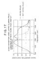
- Fig. 17 shows results of an experiment conducted using a double aluminum foil 100 free of holes with results of an experiment conducted using a double aluminum foil 100 formed with holes.
- L was set to 10 mm.
Landscapes
- Physics & Mathematics (AREA)
- Engineering & Computer Science (AREA)
- Acoustics & Sound (AREA)
- Multimedia (AREA)
- Soundproofing, Sound Blocking, And Sound Damping (AREA)
- Building Environments (AREA)
Abstract
Description
Claims (41)
- A sound-absorbing structure including at least a first thin film and a second thin film, said first thin film and said second thin film being layered over each other, and one or both of said first thin film and said second thin film having at least either ridges or grooves.
- The sound-absorbing structure according to claim 1, wherein through holes are formed in one or both of said first thin film and said second thin film.
- The sound-absorbing structure according to claim 2, wherein said through holes are formed in both of said first thin film and said second thin film, the through holes formed in said first thin film being formed in positions not overlapping the through holes formed in said second thin film.
- The sound-absorbing structure according to claim 2, wherein said through holes are fine holes and formed in a large number in said thin films.
- The sound-absorbing structure according to claim 1, wherein a rear member is installed at a position opposite to a sound wave incidence side with respect to said thin films.
- The sound-absorbing structure according to claim 5, wherein an air layer is formed between said thin films and said rear member.
- The sound-absorbing structure according to claim 5, wherein a distance between said rear member and said thin films is adjustable.
- The sound-absorbing structure according to claim 1, wherein a front member having air permeability is installed at a position on a sound wave incidence side with respect to said thin films.
- The sound-absorbing structure according to claim 8, wherein said front member is formed with a large number of fine holes.
- The sound-absorbing structure according to claim 1, wherein a front member having air permeability is installed at a position on a sound wave incidence side with respect to said thin films, a rear member is installed at a position opposite to said front member with respect to said thin films, and a space between said front member and said rear member is divided into plural portions in the surface direction of said thin films.
- A sound-absorbing structure including at least a first thin film and a second thin film, said first thin film and said second thin film being layered over each other, and one or both of said first thin film and said second thin film being folded so as to have mutually contacting and overlapping portions.
- The sound-absorbing structure according to claim 11, wherein through holes are formed in one or both of said first thin film and said second thin film.
- The sound-absorbing structure according to claim 12, wherein said through holes are formed in both of said first thin film and said second thin film, the through holes formed in said first thin film being formed in positions not overlapping the through holes formed in said second thin film.
- The sound-absorbing structure according to claim 12, wherein said through holes are fine holes and formed in a large number in said thin films.
- The sound-absorbing structure according to claim 11, wherein a rear member is installed at a position opposite to a sound wave incidence side with respect to said thin films.
- The sound-absorbing structure according to claim 15, wherein an air layer is formed between said thin films and said rear member.
- A sound-absorbing structure according to claim 15, wherein a distance between said rear member and said thin films is adjustable.
- The sound-absorbing structure according to claim 11, wherein a front member having air permeability is installed at a position on a sound wave incidence side with respect to said thin films.
- The sound-absorbing structure according to claim 18, wherein said front member is formed with a large number of fine holes.
- The sound-absorbing structure according to claim 11, wherein a front member having air permeability is installed at a position on a sound wave incidence side with respect to said thin films, a rear member is installed at a position opposite to said front member with respect to said thin films, and a space between said front member and said rear member is divided into plural portions in the surface direction of said thin films.
- A sound-absorbing structure including at least a first thin film and a second thin film, said first thin film and said second thin film being layered over each other, and through holes being formed in one or both of said first thin film and said second thin film.
- The sound-absorbing structure according to claim 21, wherein said through holes are formed in both of said first thin film and said second thin film, the through holes formed in said first thin film being formed in positions not overlapping the through holes formed in said second thin film.
- The sound-absorbing structure according to claim 21, wherein said through holes are fine through holes and are formed in a large number in said thin films.
- The sound-absorbing structure according to claim 21, wherein a rear member is installed at a position opposite to a sound wave incidence side with respect to said thin films.
- The sound-absorbing structure according to claim 24, wherein an air layer is formed between said thin films and said rear member.
- The sound-absorbing structure according to claim 24, wherein a distance between said rear member and said thin films is adjustable.
- The sound-absorbing structure according to claim 21, wherein a front member having air permeability is installed at a position on a sound wave incidence side with respect to said thin films.
- The sound-absorbing structure according to claim 27, wherein said front member is formed with a large number of fine holes.
- The sound-absorbing structure according to claim 21, wherein a front member having air permeability is installed at a position on a sound wave incidence side with respect to said thin films, a rear member is installed at a position opposite to said front member with respect to said thin films, and a space between said front member and said rear member is divided into plural portions in the surface direction of said thin films.
- A sound-absorbing structure including at least one thin film folded so as to have mutually contacting and overlapping portions.
- The sound-absorbing structure according to claim 30, wherein through holes are formed in said thin film.
- The sound-absorbing structure according to claim 30, wherein a rear member is installed at a position opposite to a sound wave incidence side with respect to said thin film.
- A sound-absorbing structure according to claim 32, wherein an air layer is formed between said thin film and said rear member.
- The sound-absorbing structure according to claim 32, wherein a distance between said rear member and said thin film is adjustable.
- The sound-absorbing structure according to claim 30, wherein a front member having air permeability is installed at a position on a sound wave incidence side with respect to said thin film.
- The sound-absorbing structure according to claim 35, wherein said front member is formed with a large number of fine holes.
- The sound-absorbing structure according to claim 30, wherein a front member having air permeability is installed at a position on a sound wave incidence side with respect to said thin film, a rear member is installed at a position opposite to said front member with respect to said thin film, and a space between said front member and said rear member is divided into plural portions in the surface direction of said thin film.
- A sound-absorbing structure including at least a first thin film and a second thin film, said first thin film and said second thin film being layered over each other, and an air-permeable front member being installed at a position on a sound wave incidence side with respect to said thin films.
- The sound-absorbing structure according to claim 38, wherein said front member is formed with a large number of fine holes.
- The sound-absorbing structure according to claim 38, wherein a rear member is installed at a position opposite to a sound wave incidence side with respect to said thin films.
- The sound-absorbing structure according to claim 38, wherein a front member having air permeability is installed at a position on a sound wave incidence side with respect to said thin films, a rear member is installed at a position opposite to said front member with respect to said thin films, and a space between said front member and said rear member is divided into plural portions in the surface direction of said thin films.
Applications Claiming Priority (3)
| Application Number | Priority Date | Filing Date | Title |
|---|---|---|---|
| JP2003046531 | 2003-02-24 | ||
| JP2003046531A JP2004264374A (en) | 2003-02-24 | 2003-02-24 | Sound absorbing structure using thin film |
| PCT/JP2004/000593 WO2004075163A1 (en) | 2003-02-24 | 2004-01-23 | Sound-absorbing structure using thin film |
Publications (2)
| Publication Number | Publication Date |
|---|---|
| EP1598808A1 true EP1598808A1 (en) | 2005-11-23 |
| EP1598808A4 EP1598808A4 (en) | 2008-07-23 |
Family
ID=32905550
Family Applications (1)
| Application Number | Title | Priority Date | Filing Date |
|---|---|---|---|
| EP04704720A Withdrawn EP1598808A4 (en) | 2003-02-24 | 2004-01-23 | Sound-absorbing structure using thin film |
Country Status (6)
| Country | Link |
|---|---|
| US (1) | US20060096183A1 (en) |
| EP (1) | EP1598808A4 (en) |
| JP (1) | JP2004264374A (en) |
| KR (1) | KR100772261B1 (en) |
| CN (1) | CN1754201B (en) |
| WO (1) | WO2004075163A1 (en) |
Cited By (1)
| Publication number | Priority date | Publication date | Assignee | Title |
|---|---|---|---|---|
| CN102081924A (en) * | 2009-11-30 | 2011-06-01 | 株式会社神户制钢所 | Sound insulation material, sound insulation system and manufacturing method of sound insulation material |
Families Citing this family (18)
| Publication number | Priority date | Publication date | Assignee | Title |
|---|---|---|---|---|
| JP2006292381A (en) * | 2005-04-05 | 2006-10-26 | Tokyo Gas Co Ltd | Ultrasonic flow meter |
| JP2008275906A (en) * | 2007-04-27 | 2008-11-13 | Iida Sangyo Kk | Sound absorbing material and manufacturing method of sheet base material used for the same |
| CN102057421B (en) * | 2008-04-14 | 2014-12-10 | 3M创新有限公司 | Multilayer sound absorbing sheet |
| KR101793278B1 (en) * | 2008-04-22 | 2017-11-02 | 쓰리엠 이노베이티브 프로퍼티즈 컴파니 | Hybrid sound absorbing sheet |
| KR101709353B1 (en) * | 2008-05-22 | 2017-02-22 | 쓰리엠 이노베이티브 프로퍼티즈 컴파니 | Multilayer sound absorbing structure comprising mesh layer |
| JP2009288355A (en) * | 2008-05-28 | 2009-12-10 | Yamaha Corp | Sound absorbing body |
| CN102760430A (en) * | 2012-08-06 | 2012-10-31 | 株洲时代新材料科技股份有限公司 | Double-layer composite micropunch sound absorption method and sound absorption panel |
| CN102820029B (en) * | 2012-08-24 | 2014-06-18 | 广州市泰力高复合材料有限公司 | Muffling structure |
| JP5918662B2 (en) * | 2012-09-04 | 2016-05-18 | 株式会社神戸製鋼所 | Porous sound absorbing structure |
| CN104822118B (en) * | 2015-05-06 | 2018-11-30 | 歌尔股份有限公司 | A kind of encapsulating structure of MEMS microphone |
| CN107615374B (en) * | 2015-06-09 | 2021-02-05 | Agc株式会社 | Film and sound-absorbing structure |
| WO2017111695A1 (en) | 2015-12-22 | 2017-06-29 | Razer (Asia-Pacific) Pte. Ltd. | Mesh assemblies, computing systems, and methods for manufacturing a mesh assembly |
| US20170256251A1 (en) * | 2016-03-01 | 2017-09-07 | Guardian Industries Corp. | Acoustic wall assembly having double-wall configuration and active noise-disruptive properties, and/or method of making and/or using the same |
| US10354638B2 (en) * | 2016-03-01 | 2019-07-16 | Guardian Glass, LLC | Acoustic wall assembly having active noise-disruptive properties, and/or method of making and/or using the same |
| CN106223501A (en) * | 2016-08-30 | 2016-12-14 | 河北正翰建筑材料有限公司 | Coating type heat insulation sound absorbent cotton |
| CN111033608A (en) * | 2017-08-22 | 2020-04-17 | 富士胶片株式会社 | Sound insulation structure and sound absorption panel |
| CN111785241B (en) * | 2020-07-08 | 2022-12-27 | 拾音汽车科技(上海)有限公司 | Radiation type multidirectional dispersed sound absorbing material |
| EP4774715A1 (en) * | 2023-09-08 | 2026-07-15 | Technische Universiteit Eindhoven | Anechoic broadband compact (abc) muffler with moving blade and vehicle applications |
Family Cites Families (19)
| Publication number | Priority date | Publication date | Assignee | Title |
|---|---|---|---|---|
| FR1378150A (en) * | 1963-09-18 | 1964-11-13 | Comp Generale Electricite | Thermal insulation device |
| JPS5293302A (en) * | 1976-02-02 | 1977-08-05 | Kowa Kasei | Sound absorbing wall |
| DE3022850A1 (en) * | 1980-06-19 | 1982-01-07 | Howaldtswerke-Deutsche Werft Ag Hamburg Und Kiel, 2300 Kiel | Anti-noise barrier constructional system - uses perforated and unperforated metal sheet with flat and corrugated foil, some perforated, compressed between them |
| DE3504208A1 (en) * | 1985-02-07 | 1986-08-07 | Fraunhofer-Gesellschaft zur Förderung der angewandten Forschung e.V., 8000 München | MUFFLER BOX |
| US5134014A (en) * | 1991-01-28 | 1992-07-28 | Eften, Inc. | Moldable foam composite |
| US5124191A (en) * | 1991-03-11 | 1992-06-23 | Aluminum Company Of America | Structural panel |
| CA2091288C (en) * | 1992-03-13 | 1995-11-28 | Toru Morimoto | Membranous-vibration sound absorbing materials |
| US5244745A (en) * | 1992-04-16 | 1993-09-14 | Aluminum Company Of America | Structural sheet and panel |
| DE4408782A1 (en) * | 1994-03-15 | 1995-09-21 | Fraunhofer Ges Forschung | Foil sound absorber |
| JP3072238B2 (en) * | 1994-05-25 | 2000-07-31 | 株式会社ユニックス | Sound absorbing curtain, sound absorbing curtain structure, and sound absorbing panel |
| DE9414943U1 (en) * | 1994-09-14 | 1996-01-18 | M. Faist GmbH & Co KG, 86381 Krumbach | Foil resonance absorber |
| US5851626A (en) * | 1997-04-22 | 1998-12-22 | Lear Corporation | Vehicle acoustic damping and decoupling system |
| US5939212A (en) * | 1997-06-09 | 1999-08-17 | Atd Corporation | Flexible corrugated multilayer metal foil shields and method of making |
| US6276044B1 (en) * | 1997-06-09 | 2001-08-21 | Atd Corporation | Shaped multilayer metal foil shield structures and method of making |
| GB9816203D0 (en) * | 1998-07-25 | 1998-09-23 | T & N Composites Limited | Improvements in and relating to composite materials |
| KR20010089326A (en) * | 1998-10-20 | 2001-09-29 | 지.윌리암 래그랜드 | Corrugated multilayer metal foil insulation panels and methods of making |
| EP1020846B1 (en) * | 1999-01-14 | 2018-09-19 | Nichias Corporation | Sound absorbing structure |
| EP1149233B2 (en) * | 1999-02-02 | 2008-09-10 | Rieter Automotive (International) Ag | Method of producing a sound-absorbent insulating element and insulating element produced according to this method |
| JP2003531025A (en) * | 2000-04-17 | 2003-10-21 | リーテル・オートモティブ・(インターナショナル)・アーゲー | Method for producing an acoustically effective foil laminate for use in thermal insulation of vehicles |
-
2003
- 2003-02-24 JP JP2003046531A patent/JP2004264374A/en active Pending
-
2004
- 2004-01-23 US US10/545,108 patent/US20060096183A1/en not_active Abandoned
- 2004-01-23 KR KR1020057015537A patent/KR100772261B1/en not_active Expired - Lifetime
- 2004-01-23 WO PCT/JP2004/000593 patent/WO2004075163A1/en not_active Ceased
- 2004-01-23 EP EP04704720A patent/EP1598808A4/en not_active Withdrawn
- 2004-01-23 CN CN2004800050397A patent/CN1754201B/en not_active Expired - Lifetime
Cited By (2)
| Publication number | Priority date | Publication date | Assignee | Title |
|---|---|---|---|---|
| CN102081924A (en) * | 2009-11-30 | 2011-06-01 | 株式会社神户制钢所 | Sound insulation material, sound insulation system and manufacturing method of sound insulation material |
| CN102081924B (en) * | 2009-11-30 | 2013-07-31 | 株式会社神户制钢所 | Sound insulation material, sound insulation system and manufacturing method of sound insulation material |
Also Published As
| Publication number | Publication date |
|---|---|
| CN1754201B (en) | 2010-09-01 |
| US20060096183A1 (en) | 2006-05-11 |
| JP2004264374A (en) | 2004-09-24 |
| KR100772261B1 (en) | 2007-11-01 |
| WO2004075163A1 (en) | 2004-09-02 |
| CN1754201A (en) | 2006-03-29 |
| KR20050106028A (en) | 2005-11-08 |
| EP1598808A4 (en) | 2008-07-23 |
Similar Documents
| Publication | Publication Date | Title |
|---|---|---|
| US20060096183A1 (en) | Sound-absorbing structure using thin film | |
| TWI299853B (en) | ||
| KR0157277B1 (en) | Sound-absorbing mechanism using porous material | |
| US4226299A (en) | Acoustical panel | |
| US7010143B2 (en) | Rectangular panel-form loudspeaker and its radiating panel | |
| WO2018192484A1 (en) | Acoustic material structure and method for assembling same and acoustic radiation structure | |
| US20080069395A1 (en) | Planar Speaker Driver | |
| JPH0437994B2 (en) | ||
| WO2013054902A1 (en) | Translucent sound-absorbing panel | |
| CN102077272A (en) | Hybrid sound absorbing sheet | |
| WO2006080150A1 (en) | Double-wall structure | |
| US20190122649A1 (en) | Broadband acoustic absorption metamaterials | |
| JP2878091B2 (en) | Acoustic panel and acoustic device using porous structure module | |
| JP5286949B2 (en) | Sound absorption structure | |
| JP4027068B2 (en) | Sound absorbing material | |
| US11227573B2 (en) | Acoustic panel with acoustic unit layer | |
| US20230405965A1 (en) | Composite structure for noise insulation applicable to broadband frequencies and multiple composite sheet including the same | |
| JP4258288B2 (en) | Sound absorbing structure | |
| JP4114463B2 (en) | Sound absorbing structure and sound absorbing and insulating structure | |
| EP4718438A1 (en) | Sound absorber | |
| JP7690167B2 (en) | Sound absorbing material | |
| CN221398704U (en) | Double-sided sound absorption type sound barrier | |
| JP2003150170A (en) | Sound absorbing material | |
| JP4155006B2 (en) | Sound absorbing structure | |
| JP2025082210A (en) | Soundproof material |
Legal Events
| Date | Code | Title | Description |
|---|---|---|---|
| PUAI | Public reference made under article 153(3) epc to a published international application that has entered the european phase |
Free format text: ORIGINAL CODE: 0009012 |
|
| 17P | Request for examination filed |
Effective date: 20050822 |
|
| AK | Designated contracting states |
Kind code of ref document: A1 Designated state(s): AT BE BG CH CY CZ DE DK EE ES FI FR GB GR HU IE IT LI LU MC NL PT RO SE SI SK TR |
|
| AX | Request for extension of the european patent |
Extension state: AL LT LV MK |
|
| DAX | Request for extension of the european patent (deleted) | ||
| A4 | Supplementary search report drawn up and despatched |
Effective date: 20080624 |
|
| RIC1 | Information provided on ipc code assigned before grant |
Ipc: G10K 11/172 20060101ALI20080618BHEP Ipc: G10K 11/168 20060101AFI20080618BHEP |
|
| 17Q | First examination report despatched |
Effective date: 20100907 |
|
| STAA | Information on the status of an ep patent application or granted ep patent |
Free format text: STATUS: THE APPLICATION IS DEEMED TO BE WITHDRAWN |
|
| 18D | Application deemed to be withdrawn |
Effective date: 20110118 |