EP1598644A1 - Electromagnetic flow meter and production method thereof - Google Patents
Electromagnetic flow meter and production method thereof Download PDFInfo
- Publication number
- EP1598644A1 EP1598644A1 EP05010775A EP05010775A EP1598644A1 EP 1598644 A1 EP1598644 A1 EP 1598644A1 EP 05010775 A EP05010775 A EP 05010775A EP 05010775 A EP05010775 A EP 05010775A EP 1598644 A1 EP1598644 A1 EP 1598644A1
- Authority
- EP
- European Patent Office
- Prior art keywords
- electrodes
- fluid
- measured
- electromagnetic flowmeter
- processed
- Prior art date
- Legal status (The legal status is an assumption and is not a legal conclusion. Google has not performed a legal analysis and makes no representation as to the accuracy of the status listed.)
- Granted
Links
Images
Classifications
-
- G—PHYSICS
- G01—MEASURING; TESTING
- G01F—MEASURING VOLUME, VOLUME FLOW, MASS FLOW OR LIQUID LEVEL; METERING BY VOLUME
- G01F1/00—Measuring the volume flow or mass flow of fluid or fluent solid material wherein the fluid passes through a meter in a continuous flow
- G01F1/56—Measuring the volume flow or mass flow of fluid or fluent solid material wherein the fluid passes through a meter in a continuous flow by using electric or magnetic effects
- G01F1/58—Measuring the volume flow or mass flow of fluid or fluent solid material wherein the fluid passes through a meter in a continuous flow by using electric or magnetic effects by electromagnetic flowmeters
- G01F1/584—Measuring the volume flow or mass flow of fluid or fluent solid material wherein the fluid passes through a meter in a continuous flow by using electric or magnetic effects by electromagnetic flowmeters constructions of electrodes, accessories therefor
Definitions
- the present invention relates to an electromagnetic flowmeter which applies a magnetic field to a fluid to be measured and picks up an electromotive force generated according to a flow rate of the fluid to be measured, and a production method thereof.
- Such an electromagnetic flowmeter is arranged to allow the electrodes to pick up an electromotive force generated according to the flow rate of a fluid to be measured when a magnetic field is applied to the fluid (not shown).
- the electrodes of the electromagnetic flowmeter are adapted to pick up an electromotive force.
- An electromagnetic flowmeter generates a flow noise when electric charge moves between the surface of the electrodes and the fluid to be measured. It is also known that when the electrodes of an electromagnetic flowmeter are soaked in a fluid to be measured (e.g., water) for a long period of time, the flow noise reduces.
- a fluid to be measured e.g., water
- flow noise as used herein is meant to indicate a noise generated when the fluid to be measured rubs against the lined surface (electrode), i.e., noise generated by electric charge with the movement of a fluid to be measured, remarkably a fluid having a low electrical conductivity and a low viscosity such as alcohol and pure water.
- the flow noise falls when the dynamic viscosity or electrical conductivity of the fluid to be measured rises but rises when the flow rate of the fluid to be measured rises.
- Figs. 4 to 6 Specific flow noise characteristics will be described hereinafter in connection with Figs. 4 to 6.
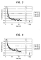
- the abscissa indicates the time during which the fluid to be measured flows through the measuring tube of the electromagnetic flowmeter (since the time at which the measuring tube comes in contact with the fluid) and the ordinate indicates the magnitude of flow noise.
- B-1 to B-9, C-1 to C-3 and D-1 to D-3 each indicate the measurements of the respective sample that are dispersed by the difference in properties between electrodes.
- Fig. 4 illustrates the flow noise characteristics of a related art electromagnetic flowmeter wherein there is provided a couple of electrodes which have been left as it is lathed. As can be seen in the characteristics of Fig. 4, the flow noise maintains a high level after the contact with the fluid and, even after several hours, doesn't readily fall and is much dispersed.
- Fig. 5 illustrates the flow noise characteristics of a related art electromagnetic flowmeter wherein there is provided a couple of electrodes which have been lathed and buffed to smoothen the surface of the substrate. As can be seen in the characteristics of Fig. 5, the flow noise is large after the contact with the fluid but falls after the lapse of time.
- Fig. 6 illustrates the flow noise characteristics of a related art electromagnetic flowmeter wherein there is provided a couple of electrodes which have been lathed and forcedly oxidized in the atmosphere. As can be seen in the characteristics of Fig. 6, the flow noise is large after the contact with the fluid but falls after the lapse of time. The flow noise in the characteristics of Fig. 6 is larger than that of Fig. 5.
- an electromagnetic flowmeter has a step of assembling a couple of electrodes in a measuring tube (product assembly), a step of soaking the electrodes in a fluid to be measured for a predetermined period of time, and a step of correcting the electromagnetic flowmeter.
- a step of soaking the electrodes again in the fluid to be measured is then executed. Subsequently, a step of correcting the electromagnetic flowmeter is executed.
- Some related art of electromagnetic flowmeters has a couple of oxidized electrodes (see, e.g., the following document (1).).
- the electromagnetic flowmeters as the related art generate much flow noise shortly after coming in contact with a fluid. Further, the generated flow noise doesn't readily fall even after the lapse of time from the contact with the fluid. Further, the generated flow noise is much dispersed by the difference in properties between electrodes.
- the step of soaking the electrodes of the electromagnetic flowmeter in the fluid to be measured and the step of correcting the electromagnetic flowmeter require much time, it takes long time to produce the electromagnetic flowmeter.
- the invention provides an electromagnetic flowmeter, having: a measuring tube through which a fluid to be measured flows; a magnetic field applying section which applies a magnetic field to the fluid to be measured; and a couple of electrodes which pick up an electromotive force generated according to a flow rate of the fluid to be measured, wherein each of the electrodes has an interface processed by electropolishing.
- each of the electrodes has an interface processed by immersing in the fluid to be measured.
- the interface processed by the electropolishing is processed by applying a positive DC voltage to the electrodes.
- the interface processed by the electropolishing is processed by applying an AC voltage to the electrodes.
- the interface processed by the electropolishing is processed by applying a voltage including a positive DC voltage and an AC voltage superposed on each other to the electrodes.
- the invention provides a production method of an electromagnetic flowmeter having a measuring tube through which a fluid to be measured flows, a magnetic field applying section which applies a magnetic field to the fluid to be measured, and a couple of electrodes which pick up an electromotive force generated according to a flow rate of the fluid to be measured, including the steps of: electropolishing the electrodes; and assembling the electrodes in the measuring tube.
- the production method of an electromagnetic flowmeter further includes the steps of: immersing the electrodes in the fluid to be measured between the step of electropolishing the electrodes and the step of assembling the electrodes in the measuring tube.
- the invention provides an electromagnetic flowmeter, having: a measuring tube through which a fluid to be measured flows; a magnetic field applying section which applies a magnetic field to the fluid to be measured; and a couple of electrodes which pick up an electromotive force generated according to a flow rate of the fluid to be measured, wherein each of the electrodes has an interface which composed a chromium density higher than iron density at a depth of 50 angstrom or less.
- each of the electrodes has an interface processed by immersing in the fluid to be measured.
- each of the interfaces is processed by applying a positive DC voltage to the electrodes.
- each of the interfaces is processed by applying an AC voltage to the electrodes.
- an electromagnetic flowmeter which generates small flow noise since shortly after coming in contact with a fluid and can be produced in a short period of time and a production method of the electromagnetic flowmeter can be provided. Further, a electromagnetic flowmeter being stable and having a high precision and a production method of the electromagnetic flowmeter can be provided.
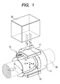
- Fig. 1 is a configurational diagram illustrating an embodiment of implementation of the invention.
- the electromagnetic flowmeter has a couple of electrodes 10, a measuring tube 13, a converter 20, a core 11, and an exciting coil 12.
- Each of the electrodes 10 is assembling in the measuring tube 13.
- the electrodes 10 are electrically connected to the converter 20.
- the core 11 and the exciting coil 12 are formed adjacent to the measuring tube 13.
- the exciting coil 12 is electrically connected to the converter 20.
- a fluid to be measured 30 e.g., water flows through the measuring tube 13.
- the core 11 and the exciting coil 12 apply a magnetic field to the fluid to be measured 30.
- the electrodes 10 pick up an electromotive force generated according to the flow rate of the fluid to be measured 30.
- the converter 20 outputs a signal corresponding to the flow rate of the fluid to be measured 30.
- the flow rate of the fluid to be measured 30 is measured.
- the configuration of the electrodes 10 will be described hereinafter.
- the surfaces of the electrodes 10 have an interface processed by electropolishing. Further, the electrodes 10 are made of stainless steel.
- the electropolishing is a technique for forming an extremely smooth and glossy surface by making the use of anode dissolution phenomena, i.e., characteristic that when electric current flows through stainless steel or the like in an electrolytic solution, a raised portion dissolves earlier than an indented portion.
- the surfaces of the electrodes 10 are chemically dissolved to a thickness on the order of micrometer to form an interface thereon.
- the surfaces of the electrodes 10 are electropolished so that it is electrochemically dissolved to a thickness on the order of angstrom ( ⁇ ) to form an interface thereon.
- the electrolyte in the vicinity of the surfaces of the electrodes 10 have their metal ions concentrated, making it more difficult for metal to dissolve. And, when it is tried to force the metal to be dissolved by passing DC current through the electrodes 10, the raised portion is preferentially dissolved because electric current can easily flow through the raised portion but difficultly flow through the indented portion. Therefore, the interfaces of the electrodes 10 are smoothened by electropolishing.
- the interfaces of the electrodes 10 have their chromium concentration raised when electropolished. In other words, the interfaces of the electrodes 10 have chromium-rich layers processed thereon.
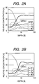
- Figs. 2A and 2B are configurational diagrams of the interfaces of the electrodes 10 according to the embodiment of Fig. 1.
- Fig. 2A illustrates the interfaces of the electrodes 10 before electropolishing.
- Fig. 2B illustrates the interfaces of the electrodes 10 after electropolishing.
- the abscissa indicates the depth from the interface, and the ordinate indicates the relative ratio of components.
- the density of chromium (Cr) is much lower than the density of iron (Fe) (Cr/Fe ⁇ 1) as shown in Fig. 2A.
- the density of chromium (Cr) is higher than the density of iron (Fe) (Cr/Fe > 1) at a depth of 50 angstrom [ ⁇ ] as shown in Fig. 2B.
- a dense interface adaptable to the fluid to be measured was processed. Once processed, the dense interface adaptable to the fluid to be measured maintained its adaptability to the fluid to be measured even when allowed to stand in the atmosphere.
- the surfaces of the electrodes 10 have a passivity film processed thereon to exhibit an enhanced corrosion resistance.
- the surfaces of the electrodes 10 are protected by a chromium oxide film or the like to have stabilized characteristics.
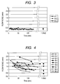
- FIG. 3 illustrates the flow noise characteristics of the embodiment of Fig. 1 wherein the electromagnetic flowmeter has electrodes 10 obtained by lathing a metal, electropolishing the metal thus lathed, and then immediately immersing the material in a fluid to be measured (water) for a predetermined period of time (e.g., 4 days).
- the characteristics of Fig. 3 correspond to that of Figs. 4 to 6.
- A-1 to A-3 each indicate the measurements of the respective sample that are dispersed by the difference in properties among electrodes.
- the flow noise had kept a small magnitude and dispersion since shortly after starting of flow of the fluid to be measured 30 through the measuring tube 13 of the electromagnetic flowmeter.
- the embodiment of Fig. 1 had showed small flow noise since shortly after coming in contact with the fluid and exhibited a high precision and stabilized characteristics. Further, in the embodiment of Fig. 1, accurate correction was easily made shortly after assembly of product.
- the electrodes 10 which have been electropolished to form an interface thereon is allowed to stand in the atmosphere, the electrodes 10 are oxidized by the air to form an interface which can be difficultly adapted to the fluid to be measured.
- the interface (which can be difficultly adapted to the fluid to be measured) processed by allowing the electrodes 10 to stand in the atmosphere differs from the interface (which is adaptable to the fluid to be measured) processed by immersing the aforementioned electrodes 10 in the fluid to be measured.
- a process for the production of an electromagnetic flowmeter according to the invention will be described hereinafter. Firstly, steps of lathing the surfaces of the electrodes 10 and then electropolishing the electrodes 10 are executed. An interface is processed on the surfaces of the electrodes 10 by electropolishing. At this time, the surfaces of the electrodes 10 are smoothened.
- a step of assembling the electrodes 10 in the measuring tube 13 is executed.
- a step of correcting the electromagnetic flowmeter is executed.
- a process for the production of another electromagnetic flowmeter according to the invention will be described hereinafter. Firstly, steps of executing the surfaces of the electrodes 10 and then electropolishing the electrodes 10 are executed. An interface is processed on the surfaces of the electrodes 10 by electropolishing.
- a step of immersing the electrodes 10 in a fluid to be measured is executed.
- the electrodes 10 is immersed in a fluid to be measured (water) shortly after the formation of an interface by electropolishing.
- a dense interface adaptable to the fluid to be measured is processed on the surfaces of the electrodes 10.
- a step of assembling the electrodes 10 in the measuring tube 13 is executed.
- a step of correcting the electromagnetic flowmeter is executed.
- the aforementioned process for the production of an electromagnetic flowmeter can be previously prepared before the assembly of the electrodes 10 in the measuring tube 13. Therefore, the time required for production can be reduced. Further, the time required to execute the step of correcting the electromagnetic flowmeter can be reduced.
- a first step of lathing the surfaces of the electrodes 10 and then buffing the electrodes 10 is executed.
- a second step of electropolishing the surfaces of the electrodes 10 is then executed.
- a third step of assembling the electrodes 10 in the measuring tube 13 is then executed.
- a fourth step of correcting the electromagnetic flowmeter is then executed.
- the surface conditions of the electrodes 10 treated in these steps will be further described.
- the external appearance of the surfaces of the electrodes 10 which has been buffed is mirror-like but is observed to have overlapped portions processed thereon and an abrasive and other foreign matters attached thereto.
- the external appearance of the surfaces of the electrodes 10 which has been then electropolished is not mirror-like but is observed to be free of these overlapped portions, abrasive and foreign matters. Further, the surfaces of the electrodes 10 have chromium-rich layers processed thereon.
- electropolishing may involve the application of an AC voltage to the electrodes.
- a specific embodiment of the aforementioned process for the production of an electromagnetic flowmeter will be described hereinafter.
- a step of lathing the surfaces of the electrodes 10 and then electropolishing the electrodes 10 is executed. During this procedure, an AC voltage is applied to the electrodes 10.
- a step of immersing the electrodes 10 in a fluid to be measured shortly after electropolishing is executed.
- a step of assembling the electrodes 10 in the measuring tube 13 is executed.
- a step of correcting the electromagnetic flowmeter is executed.
- the passivity film on the surfaces of the electrodes 10 is destroyed. It was newly confirmed experimentally that the electrodes 10 can form thereon a dense interface adaptable to the fluid to be measured in a shorter period of time. In other words, the time required to execute the step of immersing the electrodes 10 in the fluid to be measured can be further reduced. The time required to produce the electromagnetic flowmeter can be further reduced.
- a dense corrosion-resistant interface adaptable to the fluid to be measured can be processed on the surfaces of the electrodes 10.
- the electromagnetic flowmeter according to this embodiment generates small flow noise and exhibits stabilized characteristics.
- the electrodes may be made of a material which forms a passivity film in the air such as tantalum and titanium to attain substantially the same constitution as mentioned above and hence the same effect and advantage as mentioned above.
Landscapes
- Physics & Mathematics (AREA)
- Electromagnetism (AREA)
- Fluid Mechanics (AREA)
- General Physics & Mathematics (AREA)
- Measuring Volume Flow (AREA)
Abstract
Description
- This application is based upon and claims the benefit of priority from the prior Japanese Patent Applications No. 2004-150330 filed on May 20, 2004 and No. 2004-360820 filed on December 14, 2004, the entire contents of which are incorporated herein by reference.
- The present invention relates to an electromagnetic flowmeter which applies a magnetic field to a fluid to be measured and picks up an electromotive force generated according to a flow rate of the fluid to be measured, and a production method thereof.
- Related art of electromagnetic flowmeters are normally classified into two groups, i.e., one having a couple of electrodes which have been left cut by a lathe or fine cutter and another having a couple of electrodes which have been cut by a lathe or fine cutter and then mechanically polished (substrate adjustment) with a grinding paper, buff or the like.
- Such an electromagnetic flowmeter is arranged to allow the electrodes to pick up an electromotive force generated according to the flow rate of a fluid to be measured when a magnetic field is applied to the fluid (not shown). The electrodes of the electromagnetic flowmeter are adapted to pick up an electromotive force.
- An electromagnetic flowmeter generates a flow noise when electric charge moves between the surface of the electrodes and the fluid to be measured. It is also known that when the electrodes of an electromagnetic flowmeter are soaked in a fluid to be measured (e.g., water) for a long period of time, the flow noise reduces.
- The term "flow noise" as used herein is meant to indicate a noise generated when the fluid to be measured rubs against the lined surface (electrode), i.e., noise generated by electric charge with the movement of a fluid to be measured, remarkably a fluid having a low electrical conductivity and a low viscosity such as alcohol and pure water. In some detail, the flow noise falls when the dynamic viscosity or electrical conductivity of the fluid to be measured rises but rises when the flow rate of the fluid to be measured rises.
- Specific flow noise characteristics will be described hereinafter in connection with Figs. 4 to 6. In these figures, the abscissa indicates the time during which the fluid to be measured flows through the measuring tube of the electromagnetic flowmeter (since the time at which the measuring tube comes in contact with the fluid) and the ordinate indicates the magnitude of flow noise. In these figures, B-1 to B-9, C-1 to C-3 and D-1 to D-3 each indicate the measurements of the respective sample that are dispersed by the difference in properties between electrodes.
- Fig. 4 illustrates the flow noise characteristics of a related art electromagnetic flowmeter wherein there is provided a couple of electrodes which have been left as it is lathed.
As can be seen in the characteristics of Fig. 4, the flow noise maintains a high level after the contact with the fluid and, even after several hours, doesn't readily fall and is much dispersed. - Fig. 5 illustrates the flow noise characteristics of a related art electromagnetic flowmeter wherein there is provided a couple of electrodes which have been lathed and buffed to smoothen the surface of the substrate.
As can be seen in the characteristics of Fig. 5, the flow noise is large after the contact with the fluid but falls after the lapse of time. - Fig. 6 illustrates the flow noise characteristics of a related art electromagnetic flowmeter wherein there is provided a couple of electrodes which have been lathed and forcedly oxidized in the atmosphere.
As can be seen in the characteristics of Fig. 6, the flow noise is large after the contact with the fluid but falls after the lapse of time. The flow noise in the characteristics of Fig. 6 is larger than that of Fig. 5. - The aforementioned related art of the production method an electromagnetic flowmeter has a step of assembling a couple of electrodes in a measuring tube (product assembly), a step of soaking the electrodes in a fluid to be measured for a predetermined period of time, and a step of correcting the electromagnetic flowmeter.
- If the electromagnetic flowmeter has failed in the correcting step, a step of soaking the electrodes again in the fluid to be measured is then executed. Subsequently, a step of correcting the electromagnetic flowmeter is executed.
- Some related art of electromagnetic flowmeters has a couple of oxidized electrodes (see, e.g., the following document (1).).
- (1) Keisuke Kihara, et al., "Electrode Behavior of Electromagnetic Flowmeter", October 27, 28 and 29, 1993, 36th Proceedings of the Japan Joint Automatic Control Conference, 4,028 pp. 415
- However, the electromagnetic flowmeters as the related art generate much flow noise shortly after coming in contact with a fluid. Further, the generated flow noise doesn't readily fall even after the lapse of time from the contact with the fluid. Further, the generated flow noise is much dispersed by the difference in properties between electrodes.
- Further, the step of soaking the electrodes of the electromagnetic flowmeter in the fluid to be measured and the step of correcting the electromagnetic flowmeter require much time, it takes long time to produce the electromagnetic flowmeter.
- An object of the invention is to provide an electromagnetic flowmeter which has small flow noise and can be produced in a short period of time and a production method of the electromagnetic flowmeter. Another object of the invention is to provide a stable electromagnetic flowmeter being stable and having a high precision and a production method of the electromagnetic flowmeter.
- The invention provides an electromagnetic flowmeter, having: a measuring tube through which a fluid to be measured flows; a magnetic field applying section which applies a magnetic field to the fluid to be measured; and a couple of electrodes which pick up an electromotive force generated according to a flow rate of the fluid to be measured, wherein each of the electrodes has an interface processed by electropolishing.
In the electromagnetic flowmeter, each of the electrodes has an interface processed by immersing in the fluid to be measured.
In the electromagnetic flowmeter, the interface processed by the electropolishing is processed by applying a positive DC voltage to the electrodes.
In the electromagnetic flowmeter, the interface processed by the electropolishing is processed by applying an AC voltage to the electrodes.
In the electromagnetic flowmeter, the interface processed by the electropolishing is processed by applying a voltage including a positive DC voltage and an AC voltage superposed on each other to the electrodes.
The invention provides a production method of an electromagnetic flowmeter having a measuring tube through which a fluid to be measured flows, a magnetic field applying section which applies a magnetic field to the fluid to be measured, and a couple of electrodes which pick up an electromotive force generated according to a flow rate of the fluid to be measured, including the steps of: electropolishing the electrodes; and assembling the electrodes in the measuring tube.
The production method of an electromagnetic flowmeter further includes the steps of: immersing the electrodes in the fluid to be measured between the step of electropolishing the electrodes and the step of assembling the electrodes in the measuring tube.
The invention provides an electromagnetic flowmeter, having: a measuring tube through which a fluid to be measured flows; a magnetic field applying section which applies a magnetic field to the fluid to be measured; and a couple of electrodes which pick up an electromotive force generated according to a flow rate of the fluid to be measured, wherein each of the electrodes has an interface which composed a chromium density higher than iron density at a depth of 50 angstrom or less.
In the electromagnetic flowmeter, each of the electrodes has an interface processed by immersing in the fluid to be measured.
In the electromagnetic flowmeter, each of the interfaces is processed by applying a positive DC voltage to the electrodes.
In the electromagnetic flowmeter, each of the interfaces is processed by applying an AC voltage to the electrodes. - Consequently, an electromagnetic flowmeter which generates small flow noise since shortly after coming in contact with a fluid and can be produced in a short period of time and a production method of the electromagnetic flowmeter can be provided. Further, a electromagnetic flowmeter being stable and having a high precision and a production method of the electromagnetic flowmeter can be provided.
-
- Fig. 1 is a configurational diagram illustrating an embodiment of implementation of the invention;
- Figs. 2A and 2B are configurational diagrams of the
interface of the
electrode 10 according to an embodiment of Fig. 1; - Fig. 3 illustrating the flow noise characteristics of the embodiment of Fig. 1;
- Fig. 4 illustrates the flow noise characteristics of a related art electromagnetic flowmeter (left as it is lathed);
- Fig. 5 illustrates the flow noise characteristics of a related art electromagnetic flowmeter (lathed and buffed); and
- Fig. 6 illustrates the flow noise characteristics of a related art electromagnetic flowmeter (lathed and oxidized in the atmosphere).
-
- The invention will be further described hereinafter in connection with Fig. 1. Fig. 1 is a configurational diagram illustrating an embodiment of implementation of the invention.
- An electromagnetic flowmeter of the embodiment will be described.
As shown in Fig. 1, the electromagnetic flowmeter has a couple ofelectrodes 10, ameasuring tube 13, aconverter 20, acore 11, and anexciting coil 12. Each of theelectrodes 10 is assembling in themeasuring tube 13. Theelectrodes 10 are electrically connected to theconverter 20. Further, thecore 11 and theexciting coil 12 are formed adjacent to themeasuring tube 13. Theexciting coil 12 is electrically connected to theconverter 20. Further, a fluid to be measured 30 (e.g., water) flows through themeasuring tube 13. - The
core 11 and theexciting coil 12 apply a magnetic field to the fluid to be measured 30. Theelectrodes 10 pick up an electromotive force generated according to the flow rate of the fluid to be measured 30. Further, theconverter 20 outputs a signal corresponding to the flow rate of the fluid to be measured 30. Thus, in the embodiment, the flow rate of the fluid to be measured 30 is measured. - The configuration of the
electrodes 10 will be described hereinafter.
The surfaces of theelectrodes 10 have an interface processed by electropolishing. Further, theelectrodes 10 are made of stainless steel. - The electropolishing will be described hereinafter.
The electropolishing is a technique for forming an extremely smooth and glossy surface by making the use of anode dissolution phenomena, i.e., characteristic that when electric current flows through stainless steel or the like in an electrolytic solution, a raised portion dissolves earlier than an indented portion. - For example, when DC current flows through the
electrodes 10 as an anode (plus), that is, a positive DC voltage is applied to theelectrodes 10 in a solution in which a metal cannot be difficultly dissolved because of little water content, such as concentrated phosphoric acid and concentrated sulfuric acid, the surfaces of theelectrodes 10 are chemically dissolved to a thickness on the order of micrometer to form an interface thereon. In other words, the surfaces of theelectrodes 10 are electropolished so that it is electrochemically dissolved to a thickness on the order of angstrom (Å) to form an interface thereon. - In some detail, when electrolysis proceeds, the electrolyte in the vicinity of the surfaces of the
electrodes 10 have their metal ions concentrated, making it more difficult for metal to dissolve. And, when it is tried to force the metal to be dissolved by passing DC current through theelectrodes 10, the raised portion is preferentially dissolved because electric current can easily flow through the raised portion but difficultly flow through the indented portion. Therefore, the interfaces of theelectrodes 10 are smoothened by electropolishing. - Further, foreign matters on the interfaces of the
electrodes 10 are removed away by dissolution by electropolishing. Moreover, the interfaces of theelectrodes 10 have their chromium concentration raised when electropolished. In other words, the interfaces of theelectrodes 10 have chromium-rich layers processed thereon. - The interfaces of the
electrodes 10 will be described hereinafter in connection with Figs. 2A and 2B. Figs. 2A and 2B are configurational diagrams of the interfaces of theelectrodes 10 according to the embodiment of Fig. 1.
Fig. 2A illustrates the interfaces of theelectrodes 10 before electropolishing. Fig. 2B illustrates the interfaces of theelectrodes 10 after electropolishing. Further, in Figs. 2A and 2B, the abscissa indicates the depth from the interface, and the ordinate indicates the relative ratio of components. - Before electropolishing, the density of chromium (Cr) is much lower than the density of iron (Fe) (Cr/Fe < 1) as shown in Fig. 2A. However, after electropolishing, there occurs a region where the density of chromium (Cr) is higher than the density of iron (Fe) (Cr/Fe > 1) at a depth of 50 angstrom [Å] as shown in Fig. 2B.
- It was newly confirmed experimentally that an electromagnetic
flowmeter having electrodes 10 having interfaces thus processed by electropolishing generates small flow noise. - When the
electrodes 10 were immersed in a fluid to be measured (water) shortly after the formation of interfaces on theelectrodes 10 by electropolishing, the resulting electromagnetic flowmeter generated much less flow noise. - In some detail, when the
electrodes 10 were immersed in a fluid to be measured (water) shortly after the formation of an interface thereon by electropolishing, a dense interface adaptable to the fluid to be measured was processed. Once processed, the dense interface adaptable to the fluid to be measured maintained its adaptability to the fluid to be measured even when allowed to stand in the atmosphere. - It was newly confirmed experimentally that an electromagnetic
flowmeter having electrodes 10 having such a dense interface adaptable to the fluid to be measured generates much less flow noise. - Further, when a positive DC voltage is applied to the
electrodes 10, the surfaces of theelectrodes 10 have a passivity film processed thereon to exhibit an enhanced corrosion resistance. In other words, the surfaces of theelectrodes 10 are protected by a chromium oxide film or the like to have stabilized characteristics. - Detailed flow noise characteristics will be further described hereinafter in connection with Fig. 3. Fig. 3 illustrates the flow noise characteristics of the embodiment of Fig. 1 wherein the electromagnetic flowmeter has
electrodes 10 obtained by lathing a metal, electropolishing the metal thus lathed, and then immediately immersing the material in a fluid to be measured (water) for a predetermined period of time (e.g., 4 days). The characteristics of Fig. 3 correspond to that of Figs. 4 to 6. In Fig. 3, A-1 to A-3 each indicate the measurements of the respective sample that are dispersed by the difference in properties among electrodes. - As can be seen in the characteristics of Fig. 3, the flow noise had kept a small magnitude and dispersion since shortly after starting of flow of the fluid to be measured 30 through the measuring
tube 13 of the electromagnetic flowmeter. - As can be seen in the foregoing description, the embodiment of Fig. 1 had showed small flow noise since shortly after coming in contact with the fluid and exhibited a high precision and stabilized characteristics. Further, in the embodiment of Fig. 1, accurate correction was easily made shortly after assembly of product.
- On the other hand, when the
electrodes 10 which have been electropolished to form an interface thereon is allowed to stand in the atmosphere, theelectrodes 10 are oxidized by the air to form an interface which can be difficultly adapted to the fluid to be measured. The interface (which can be difficultly adapted to the fluid to be measured) processed by allowing theelectrodes 10 to stand in the atmosphere differs from the interface (which is adaptable to the fluid to be measured) processed by immersing theaforementioned electrodes 10 in the fluid to be measured. - A process for the production of an electromagnetic flowmeter according to the invention will be described hereinafter.
Firstly, steps of lathing the surfaces of theelectrodes 10 and then electropolishing theelectrodes 10 are executed. An interface is processed on the surfaces of theelectrodes 10 by electropolishing. At this time, the surfaces of theelectrodes 10 are smoothened. - Secondly, a step of assembling the
electrodes 10 in the measuringtube 13 is executed. Thirdly, a step of correcting the electromagnetic flowmeter is executed. - A process for the production of another electromagnetic flowmeter according to the invention will be described hereinafter.
Firstly, steps of executing the surfaces of theelectrodes 10 and then electropolishing theelectrodes 10 are executed. An interface is processed on the surfaces of theelectrodes 10 by electropolishing. - Secondly, a step of immersing the
electrodes 10 in a fluid to be measured is executed. In some detail, theelectrodes 10 is immersed in a fluid to be measured (water) shortly after the formation of an interface by electropolishing. A dense interface adaptable to the fluid to be measured is processed on the surfaces of theelectrodes 10. - Thirdly, a step of assembling the
electrodes 10 in the measuringtube 13 is executed. Fourthly, a step of correcting the electromagnetic flowmeter is executed. - The aforementioned process for the production of an electromagnetic flowmeter can be previously prepared before the assembly of the
electrodes 10 in the measuringtube 13. Therefore, the time required for production can be reduced. Further, the time required to execute the step of correcting the electromagnetic flowmeter can be reduced. - Separately of the aforementioned embodiments, a first step of lathing the surfaces of the
electrodes 10 and then buffing theelectrodes 10 is executed. A second step of electropolishing the surfaces of theelectrodes 10 is then executed. A third step of assembling theelectrodes 10 in the measuringtube 13 is then executed. A fourth step of correcting the electromagnetic flowmeter is then executed. - The surface conditions of the
electrodes 10 treated in these steps will be further described. The external appearance of the surfaces of theelectrodes 10 which has been buffed is mirror-like but is observed to have overlapped portions processed thereon and an abrasive and other foreign matters attached thereto. The external appearance of the surfaces of theelectrodes 10 which has been then electropolished is not mirror-like but is observed to be free of these overlapped portions, abrasive and foreign matters. Further, the surfaces of theelectrodes 10 have chromium-rich layers processed thereon. - It was newly confirmed experimentally that when these steps are executed, the surfaces of the
electrodes 10 are further smoothened and the resulting electromagnetic flowmeter thus generates much less flow noise. The effect of buffing on the flow noise of the electromagnetic flowmeter is smaller than the effect of electropolishing on the flow noise of the electromagnetic flowmeter. - While the aforementioned embodiments have been described with reference to the case where electropolishing involves the application of a positive DC voltage to the electrodes, electropolishing may involve the application of an AC voltage to the electrodes.
- A specific embodiment of the aforementioned process for the production of an electromagnetic flowmeter will be described hereinafter. Firstly, a step of lathing the surfaces of the
electrodes 10 and then electropolishing theelectrodes 10 is executed. During this procedure, an AC voltage is applied to theelectrodes 10. Secondly, a step of immersing theelectrodes 10 in a fluid to be measured shortly after electropolishing is executed. Thirdly, a step of assembling theelectrodes 10 in the measuringtube 13 is executed. Fourthly, a step of correcting the electromagnetic flowmeter is executed. - In the foregoing embodiments, the passivity film on the surfaces of the
electrodes 10 is destroyed. It was newly confirmed experimentally that theelectrodes 10 can form thereon a dense interface adaptable to the fluid to be measured in a shorter period of time. In other words, the time required to execute the step of immersing theelectrodes 10 in the fluid to be measured can be further reduced. The time required to produce the electromagnetic flowmeter can be further reduced. - Further, when electropolishing involves the application of a positive DC voltage and an AC voltage to the electrodes, a dense corrosion-resistant interface adaptable to the fluid to be measured can be processed on the surfaces of the
electrodes 10. The electromagnetic flowmeter according to this embodiment generates small flow noise and exhibits stabilized characteristics. - While the embodiment has been described with reference to the case where the electrodes are made of stainless steel, the electrodes may be made of a material which forms a passivity film in the air such as tantalum and titanium to attain substantially the same constitution as mentioned above and hence the same effect and advantage as mentioned above.
- As mentioned above, the invention is not limited to the embodiment and various changes and modifications can be made therein without departing from the spirit and scope thereof.
Claims (11)
- An electromagnetic flowmeter, comprising:wherein each of the electrodes has an interface processed by electropolishing.a measuring tube through which a fluid to be measured flows;a magnetic field applying section which applies a magnetic field to the fluid to be measured; anda couple of electrodes which pick up an electromotive force generated according to a flow rate of the fluid to be measured,
- The electromagnetic flowmeter according to claim 1,
wherein each of the electrodes has an interface processed by immersing in the fluid to be measured. - The electromagnetic flowmeter according to claim 1,
wherein the interface processed by the electropolishing is processed by applying a positive DC voltage to the electrodes. - The electromagnetic flowmeter according to claim 1,
wherein the interface processed by the electropolishing is processed by applying an AC voltage to the electrodes. - The electromagnetic flowmeter according to claim 1,
wherein the interface processed by the electropolishing is processed by applying a voltage including a positive DC voltage and an AC voltage superposed on each other to the electrodes. - A production method of an electromagnetic flowmeter comprising a measuring tube through which a fluid to be measured flows, a magnetic field applying section which applies a magnetic field to the fluid to be measured, and a couple of electrodes which pick up an electromotive force generated according to a flow rate of the fluid to be measured, comprising the steps of:electropolishing the electrodes; andassembling the electrodes in the measuring tube.
- The production method of an electromagnetic flowmeter according to claim 6, further comprising the steps of:immersing the electrodes in the fluid to be measured between the step of electropolishing the electrodes and the step of assembling the electrodes in the measuring tube.
- An electromagnetic flowmeter, comprising:wherein each of the electrodes has an interface which has a chromium density higher than iron density at a depth of 50 angstrom or less.a measuring tube through which a fluid to be measured flows;a magnetic field applying section which applies a magnetic field to the fluid to be measured; anda couple of electrodes which pick up an electromotive force generated according to a flow rate of the fluid to be measured,
- The electromagnetic flowmeter according to claim 8,
wherein each of the electrodes has an interface processed by immersing in the fluid to be measured. - The electromagnetic flowmeter according to claim 8,
wherein each of the interfaces is processed by applying a positive DC voltage to the electrodes. - The electromagnetic flowmeter according to claim 8,
wherein each of the interfaces is processed by applying an AC voltage to the electrodes.
Applications Claiming Priority (4)
| Application Number | Priority Date | Filing Date | Title |
|---|---|---|---|
| JP2004150330 | 2004-05-20 | ||
| JP2004150330 | 2004-05-20 | ||
| JP2004360820 | 2004-12-14 | ||
| JP2004360820A JP4665502B2 (en) | 2004-05-20 | 2004-12-14 | Electromagnetic flow meter and method for manufacturing electromagnetic flow meter |
Publications (3)
| Publication Number | Publication Date |
|---|---|
| EP1598644A1 true EP1598644A1 (en) | 2005-11-23 |
| EP1598644B1 EP1598644B1 (en) | 2016-12-28 |
| EP1598644B2 EP1598644B2 (en) | 2022-09-14 |
Family
ID=34936648
Family Applications (1)
| Application Number | Title | Priority Date | Filing Date |
|---|---|---|---|
| EP05010775.4A Expired - Lifetime EP1598644B2 (en) | 2004-05-20 | 2005-05-18 | Electromagnetic flow meter production method |
Country Status (3)
| Country | Link |
|---|---|
| US (1) | US7293469B2 (en) |
| EP (1) | EP1598644B2 (en) |
| JP (1) | JP4665502B2 (en) |
Cited By (1)
| Publication number | Priority date | Publication date | Assignee | Title |
|---|---|---|---|---|
| WO2010108517A1 (en) * | 2009-03-26 | 2010-09-30 | Siemens Aktiengesellschaft | Electropolishing method and electromagnetic flowmeter having electropolished electrodes |
Families Citing this family (8)
| Publication number | Priority date | Publication date | Assignee | Title |
|---|---|---|---|---|
| JP4754932B2 (en) * | 2005-10-17 | 2011-08-24 | 株式会社山武 | Electromagnetic flow meter |
| FR2909764B1 (en) * | 2006-12-12 | 2009-04-03 | Commissariat Energie Atomique | METHOD AND DEVICE FOR DETECTING AND / OR QUANTIFYING WATER LEAKS. |
| GB201006409D0 (en) | 2010-04-17 | 2010-06-02 | Univ Huddersfield | Means and method for mearsuring the flow rate of fluid |
| US20120037729A1 (en) * | 2010-08-16 | 2012-02-16 | Lee Joseph C | Insertion Type Fluid Volume Meter and Control System |
| DE102012016408B4 (en) * | 2012-08-21 | 2022-06-09 | Krohne Ag | Magnetic-inductive flow meter with a number of functional units, constructive realization |
| WO2015114917A1 (en) * | 2014-01-29 | 2015-08-06 | 株式会社島津製作所 | Metal electrode, and, electron gun, electron tube, and x-ray tube using same |
| CN104911686A (en) * | 2015-06-04 | 2015-09-16 | 上海大学兴化特种不锈钢研究院 | Magnetic control surface treatment method for enhancing pitting corrosion resistance of 304L stainless steel |
| US10371550B2 (en) | 2016-10-24 | 2019-08-06 | Ademco Inc. | Compact magnetic field generator for magmeter |
Citations (5)
| Publication number | Priority date | Publication date | Assignee | Title |
|---|---|---|---|---|
| US3180144A (en) * | 1960-05-20 | 1965-04-27 | George Kent Stroud Ltd | Flowmeter electrodes |
| GB1288912A (en) * | 1968-11-20 | 1972-09-13 | ||
| US4517846A (en) * | 1983-06-13 | 1985-05-21 | Flowmetering Instruments Limited | Electromagnetic flowmeter |
| JPS63180419A (en) * | 1987-01-22 | 1988-07-25 | Chuo Seisakusho:Kk | Electrolytic polishing device |
| WO2003088352A1 (en) * | 2002-04-09 | 2003-10-23 | Rensselaer Polytechnic Institute | Electrochemical planarization of metal feature surfaces |
Family Cites Families (7)
| Publication number | Priority date | Publication date | Assignee | Title |
|---|---|---|---|---|
| JPS5851230U (en) * | 1981-10-01 | 1983-04-07 | 横河電機株式会社 | electromagnetic flowmeter electrodes |
| JPS60159200A (en) * | 1984-01-27 | 1985-08-20 | Naganoken | Electropolishing method by current inverting electrolysis |
| US4736634A (en) * | 1985-12-27 | 1988-04-12 | Aichi Tokei Denki Co., Ltd. | Magnetic field generating device for electromagnetic flowmeter of residual magnetization type |
| JPS6324098A (en) * | 1986-02-28 | 1988-02-01 | Chem Yamamoto:Kk | Method for removing scale formed by welding of alloy steel |
| DE3812309C1 (en) † | 1988-04-13 | 1989-12-21 | Flowtec Ag, Reinach, Basel, Ch | |
| JP2854720B2 (en) * | 1991-04-18 | 1999-02-03 | 株式会社東芝 | Electromagnetic flow meter |
| JPH0853773A (en) * | 1994-08-10 | 1996-02-27 | Kobe Steel Ltd | High corrosion resistant surface treated metallic material and its production |
-
2004
- 2004-12-14 JP JP2004360820A patent/JP4665502B2/en not_active Expired - Fee Related
-
2005
- 2005-05-18 US US11/132,806 patent/US7293469B2/en not_active Expired - Lifetime
- 2005-05-18 EP EP05010775.4A patent/EP1598644B2/en not_active Expired - Lifetime
Patent Citations (5)
| Publication number | Priority date | Publication date | Assignee | Title |
|---|---|---|---|---|
| US3180144A (en) * | 1960-05-20 | 1965-04-27 | George Kent Stroud Ltd | Flowmeter electrodes |
| GB1288912A (en) * | 1968-11-20 | 1972-09-13 | ||
| US4517846A (en) * | 1983-06-13 | 1985-05-21 | Flowmetering Instruments Limited | Electromagnetic flowmeter |
| JPS63180419A (en) * | 1987-01-22 | 1988-07-25 | Chuo Seisakusho:Kk | Electrolytic polishing device |
| WO2003088352A1 (en) * | 2002-04-09 | 2003-10-23 | Rensselaer Polytechnic Institute | Electrochemical planarization of metal feature surfaces |
Non-Patent Citations (1)
| Title |
|---|
| PATENT ABSTRACTS OF JAPAN vol. 012, no. 448 (M - 768) 24 November 1988 (1988-11-24) * |
Cited By (1)
| Publication number | Priority date | Publication date | Assignee | Title |
|---|---|---|---|---|
| WO2010108517A1 (en) * | 2009-03-26 | 2010-09-30 | Siemens Aktiengesellschaft | Electropolishing method and electromagnetic flowmeter having electropolished electrodes |
Also Published As
| Publication number | Publication date |
|---|---|
| JP4665502B2 (en) | 2011-04-06 |
| EP1598644B1 (en) | 2016-12-28 |
| US7293469B2 (en) | 2007-11-13 |
| JP2006003339A (en) | 2006-01-05 |
| US20050268730A1 (en) | 2005-12-08 |
| EP1598644B2 (en) | 2022-09-14 |
Similar Documents
| Publication | Publication Date | Title |
|---|---|---|
| US8524068B2 (en) | Low-rate electrochemical etch of thin film metals and alloys | |
| Nagayama et al. | The anodic oxidation of iron in a neutral solution: I. The nature and composition of the passive film | |
| US7293469B2 (en) | Electromagnetic flow meter having electropolished electrodes | |
| US5486283A (en) | Method for anodizing aluminum and product produced | |
| US20090317656A1 (en) | Aluminum alloy article with micro-arc oxide for film and method for making the same | |
| EP3416771A1 (en) | Fabricating metal or ceramic components using 3d printing with dissolvable supports of a different material | |
| US11547005B2 (en) | Etching for bonding polymer material to anodized metal | |
| CN103238063A (en) | Electrode for electrochemical measurement, electrolysis cell for electrochemical measurement, analyzer for electrochemical measurement, and methods for producing same | |
| Cho et al. | The effect of electrolyte properties on the mechanism of crevice corrosion in pure iron | |
| US4756816A (en) | Electrodeposition of high moment cobalt iron | |
| EP0395111B1 (en) | Method of manufacturing high magnetic flux density electrodeposited quarternary alloy thin film | |
| Donten et al. | Voltammetric, Optical, and Spectroscopic Examination of Anodically Forced Passivation of Cobalt‐Tungsten Amorphous Alloys | |
| US3940321A (en) | Methods of treating aluminium | |
| CN100383494C (en) | Electromagnetic flowmeter and manufacturing method thereof | |
| KR102168835B1 (en) | Evaluation Method of Hydrogen Embrittlement and Stress Corrosion Properties of Steel | |
| Mogoda et al. | Formation and dissolution behaviour of ZrO2 film in H3PO4 acid solutions | |
| KR101907204B1 (en) | Anodizing method of object to be treated | |
| US10629917B2 (en) | Separator for fuel cells, fuel cell, fuel cell stack, and method of manufacturing separator for fuel cells | |
| Hryniewicz | On discrepancies between theory and practice of electropolishing | |
| US20050100758A1 (en) | Corrosion resistant conductive parts | |
| WO2010108517A1 (en) | Electropolishing method and electromagnetic flowmeter having electropolished electrodes | |
| US3647654A (en) | Beryllium-copper electropolishing solution | |
| JP2009093940A (en) | Material for separator of solid polymer fuel cell | |
| JP6124443B2 (en) | Method for producing gold porous membrane | |
| Isaacs et al. | Current distributions and dissolution mechanisms during localized corrosion of steels in alkaline environments |
Legal Events
| Date | Code | Title | Description |
|---|---|---|---|
| PUAI | Public reference made under article 153(3) epc to a published international application that has entered the european phase |
Free format text: ORIGINAL CODE: 0009012 |
|
| AK | Designated contracting states |
Kind code of ref document: A1 Designated state(s): AT BE BG CH CY CZ DE DK EE ES FI FR GB GR HU IE IS IT LI LT LU MC NL PL PT RO SE SI SK TR |
|
| AX | Request for extension of the european patent |
Extension state: AL BA HR LV MK YU |
|
| 17P | Request for examination filed |
Effective date: 20060120 |
|
| AKX | Designation fees paid |
Designated state(s): DE FR GB |
|
| 17Q | First examination report despatched |
Effective date: 20121113 |
|
| GRAP | Despatch of communication of intention to grant a patent |
Free format text: ORIGINAL CODE: EPIDOSNIGR1 |
|
| INTG | Intention to grant announced |
Effective date: 20160719 |
|
| GRAS | Grant fee paid |
Free format text: ORIGINAL CODE: EPIDOSNIGR3 |
|
| STAA | Information on the status of an ep patent application or granted ep patent |
Free format text: STATUS: GRANT OF PATENT IS INTENDED |
|
| GRAA | (expected) grant |
Free format text: ORIGINAL CODE: 0009210 |
|
| STAA | Information on the status of an ep patent application or granted ep patent |
Free format text: STATUS: THE PATENT HAS BEEN GRANTED |
|
| AK | Designated contracting states |
Kind code of ref document: B1 Designated state(s): DE FR GB |
|
| REG | Reference to a national code |
Ref country code: GB Ref legal event code: FG4D |
|
| REG | Reference to a national code |
Ref country code: DE Ref legal event code: R096 Ref document number: 602005050989 Country of ref document: DE |
|
| REG | Reference to a national code |
Ref country code: FR Ref legal event code: PLFP Year of fee payment: 13 |
|
| REG | Reference to a national code |
Ref country code: DE Ref legal event code: R026 Ref document number: 602005050989 Country of ref document: DE |
|
| PLBI | Opposition filed |
Free format text: ORIGINAL CODE: 0009260 |
|
| PLAX | Notice of opposition and request to file observation + time limit sent |
Free format text: ORIGINAL CODE: EPIDOSNOBS2 |
|
| 26 | Opposition filed |
Opponent name: ENDRESS+HAUSER (DEUTSCHLAND) AG+CO.KG/ ENDRESS+HAU Effective date: 20170928 |
|
| PLBB | Reply of patent proprietor to notice(s) of opposition received |
Free format text: ORIGINAL CODE: EPIDOSNOBS3 |
|
| REG | Reference to a national code |
Ref country code: FR Ref legal event code: PLFP Year of fee payment: 14 |
|
| PUAH | Patent maintained in amended form |
Free format text: ORIGINAL CODE: 0009272 |
|
| STAA | Information on the status of an ep patent application or granted ep patent |
Free format text: STATUS: PATENT MAINTAINED AS AMENDED |
|
| 27A | Patent maintained in amended form |
Effective date: 20220914 |
|
| AK | Designated contracting states |
Kind code of ref document: B2 Designated state(s): DE FR GB |
|
| REG | Reference to a national code |
Ref country code: DE Ref legal event code: R102 Ref document number: 602005050989 Country of ref document: DE |
|
| REG | Reference to a national code |
Ref country code: FR Ref legal event code: PLFP Year of fee payment: 19 |
|
| P01 | Opt-out of the competence of the unified patent court (upc) registered |
Effective date: 20230603 |
|
| PGFP | Annual fee paid to national office [announced via postgrant information from national office to epo] |
Ref country code: GB Payment date: 20240418 Year of fee payment: 20 |
|
| PGFP | Annual fee paid to national office [announced via postgrant information from national office to epo] |
Ref country code: DE Payment date: 20240418 Year of fee payment: 20 |
|
| PGFP | Annual fee paid to national office [announced via postgrant information from national office to epo] |
Ref country code: FR Payment date: 20240418 Year of fee payment: 20 |
|
| REG | Reference to a national code |
Ref country code: DE Ref legal event code: R071 Ref document number: 602005050989 Country of ref document: DE |
|
| REG | Reference to a national code |
Ref country code: GB Ref legal event code: PE20 Expiry date: 20250517 |
|
| PG25 | Lapsed in a contracting state [announced via postgrant information from national office to epo] |
Ref country code: GB Free format text: LAPSE BECAUSE OF EXPIRATION OF PROTECTION Effective date: 20250517 |